EP1484153B1 - Machine à mouler par injection horizontale - Google Patents
Machine à mouler par injection horizontale Download PDFInfo
- Publication number
- EP1484153B1 EP1484153B1 EP04017582A EP04017582A EP1484153B1 EP 1484153 B1 EP1484153 B1 EP 1484153B1 EP 04017582 A EP04017582 A EP 04017582A EP 04017582 A EP04017582 A EP 04017582A EP 1484153 B1 EP1484153 B1 EP 1484153B1
- Authority
- EP
- European Patent Office
- Prior art keywords
- injection moulding
- tool
- horizontal injection
- moulding machine
- machine according
- Prior art date
- Legal status (The legal status is an assumption and is not a legal conclusion. Google has not performed a legal analysis and makes no representation as to the accuracy of the status listed.)
- Expired - Lifetime
Links
Images


Classifications
-
- B—PERFORMING OPERATIONS; TRANSPORTING
- B29—WORKING OF PLASTICS; WORKING OF SUBSTANCES IN A PLASTIC STATE IN GENERAL
- B29C—SHAPING OR JOINING OF PLASTICS; SHAPING OF MATERIAL IN A PLASTIC STATE, NOT OTHERWISE PROVIDED FOR; AFTER-TREATMENT OF THE SHAPED PRODUCTS, e.g. REPAIRING
- B29C45/00—Injection moulding, i.e. forcing the required volume of moulding material through a nozzle into a closed mould; Apparatus therefor
- B29C45/17—Component parts, details or accessories; Auxiliary operations
-
- B—PERFORMING OPERATIONS; TRANSPORTING
- B29—WORKING OF PLASTICS; WORKING OF SUBSTANCES IN A PLASTIC STATE IN GENERAL
- B29C—SHAPING OR JOINING OF PLASTICS; SHAPING OF MATERIAL IN A PLASTIC STATE, NOT OTHERWISE PROVIDED FOR; AFTER-TREATMENT OF THE SHAPED PRODUCTS, e.g. REPAIRING
- B29C45/00—Injection moulding, i.e. forcing the required volume of moulding material through a nozzle into a closed mould; Apparatus therefor
- B29C45/03—Injection moulding apparatus
- B29C45/04—Injection moulding apparatus using movable moulds or mould halves
- B29C45/0441—Injection moulding apparatus using movable moulds or mould halves involving a rotational movement
- B29C45/045—Injection moulding apparatus using movable moulds or mould halves involving a rotational movement mounted on the circumference of a rotating support having a rotating axis perpendicular to the mould opening, closing or clamping direction
-
- B—PERFORMING OPERATIONS; TRANSPORTING
- B29—WORKING OF PLASTICS; WORKING OF SUBSTANCES IN A PLASTIC STATE IN GENERAL
- B29C—SHAPING OR JOINING OF PLASTICS; SHAPING OF MATERIAL IN A PLASTIC STATE, NOT OTHERWISE PROVIDED FOR; AFTER-TREATMENT OF THE SHAPED PRODUCTS, e.g. REPAIRING
- B29C45/00—Injection moulding, i.e. forcing the required volume of moulding material through a nozzle into a closed mould; Apparatus therefor
- B29C45/16—Making multilayered or multicoloured articles
- B29C45/1615—The materials being injected at different moulding stations
- B29C45/1628—The materials being injected at different moulding stations using a mould carrier rotatable about an axis perpendicular to the opening and closing axis of the moulding stations
-
- B—PERFORMING OPERATIONS; TRANSPORTING
- B29—WORKING OF PLASTICS; WORKING OF SUBSTANCES IN A PLASTIC STATE IN GENERAL
- B29C—SHAPING OR JOINING OF PLASTICS; SHAPING OF MATERIAL IN A PLASTIC STATE, NOT OTHERWISE PROVIDED FOR; AFTER-TREATMENT OF THE SHAPED PRODUCTS, e.g. REPAIRING
- B29C45/00—Injection moulding, i.e. forcing the required volume of moulding material through a nozzle into a closed mould; Apparatus therefor
- B29C45/03—Injection moulding apparatus
- B29C45/04—Injection moulding apparatus using movable moulds or mould halves
- B29C45/0441—Injection moulding apparatus using movable moulds or mould halves involving a rotational movement
- B29C45/045—Injection moulding apparatus using movable moulds or mould halves involving a rotational movement mounted on the circumference of a rotating support having a rotating axis perpendicular to the mould opening, closing or clamping direction
- B29C2045/0458—Drive means for the rotating support
-
- B—PERFORMING OPERATIONS; TRANSPORTING
- B29—WORKING OF PLASTICS; WORKING OF SUBSTANCES IN A PLASTIC STATE IN GENERAL
- B29C—SHAPING OR JOINING OF PLASTICS; SHAPING OF MATERIAL IN A PLASTIC STATE, NOT OTHERWISE PROVIDED FOR; AFTER-TREATMENT OF THE SHAPED PRODUCTS, e.g. REPAIRING
- B29C45/00—Injection moulding, i.e. forcing the required volume of moulding material through a nozzle into a closed mould; Apparatus therefor
- B29C45/17—Component parts, details or accessories; Auxiliary operations
- B29C45/26—Moulds
- B29C45/32—Moulds having several axially spaced mould cavities, i.e. for making several separated articles
- B29C2045/326—Supporting means for the central mould plate
-
- B—PERFORMING OPERATIONS; TRANSPORTING
- B29—WORKING OF PLASTICS; WORKING OF SUBSTANCES IN A PLASTIC STATE IN GENERAL
- B29C—SHAPING OR JOINING OF PLASTICS; SHAPING OF MATERIAL IN A PLASTIC STATE, NOT OTHERWISE PROVIDED FOR; AFTER-TREATMENT OF THE SHAPED PRODUCTS, e.g. REPAIRING
- B29C45/00—Injection moulding, i.e. forcing the required volume of moulding material through a nozzle into a closed mould; Apparatus therefor
- B29C45/16—Making multilayered or multicoloured articles
- B29C45/1615—The materials being injected at different moulding stations
- B29C45/162—The materials being injected at different moulding stations using means, e.g. mould parts, for transferring an injected part between moulding stations
Definitions
- the invention relates to a horizontal injection molding machine according to the preamble of patent claim 1.
- a system in which the rotary block is rotatably supported in carriers, said carrier at least at the two lower bars of the injection molding machine ( US 4,330,257 ) or on all four spars ( EP 0 922 556 A1 ) is slidably guided and supported.
- said carrier at least at the two lower bars of the injection molding machine ( US 4,330,257 ) or on all four spars ( EP 0 922 556 A1 ) is slidably guided and supported.
- this support is sensitive to temperature fluctuations, ie when cooled and concomitant shrinkage, the game in the camps is greater, while heating and a concomitant expansion there is a risk that the support and guide elements jam on the bars.
- the tolerances in the support and guide elements must not be too narrow, ie not designed too precisely.
- Another disadvantage is that the spars are loaded depending on the design of the rotary block and the carrier with a considerable weight (impermissible deflection) and that the torques occurring during the rotation of the rotary block must be fully absorbed by the bars, which just when starting and braking the Rotary movement leads to considerable loads.
- the present invention seeks to provide a horizontal injection molding machine with a rotating device for injection molding, in which the spars are unloaded and at the same time the installation and removal of the tools is simplified.
- An advantage of the invention is that the turning device is completely detached from the bars and thus they are loaded with neither weight nor with torques, and that in contrast to the aforementioned US 3,828,961 can be dispensed with a hindering during tool change Traverse. This has the advantage that the tool as a whole can be easily removed and installed, so that a complex adjustment of the individual tool parts can be omitted.
- the H-shaped configuration of the base plate offers additional advantages, namely a stable support when the legs of the H are designed to be correspondingly long (dependent claim 10), as well as a slight removal of molded parts in the space between the legs of H (dependent claim 5).
- the base plate in such a way large enough that it extends to outside the range of mold clamping plates (dependent claim 11).
- a complete floor mold can be lowered in the closed state in the area between the mold clamping plates and mounted on the turntable (dependent claim 7), wherein advantageously centering means are provided.
- the opening of the tool halves is advantageously supported by hydraulic pressure cylinders in the parting planes between the middle part of the tool and the stationary or the movable mold half (dependent claim 9).
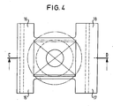
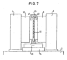
- FIGS. 1 to 6 a two-plate horizontal injection molding machine with a stack mold and a tool center plate, hereinafter referred to as a turning plate.
- a fixed platen 3 and a movable, guided on the machine bed guide 23, 24 and 25 and pulled to bars 5 to 8, platen 4 is arranged.
- a solid mold half 9 Between the tool platens are a solid mold half 9, a movable tool half 10 and between these a turntable 11 is provided.
- the clock-1 floor is formed, while between the movable mold half 10 and this facing side of the insert 11, the clock 2 level is provided.
- the clock-1 injection takes place by one of the fixed tool half associated injection unit 12, while the clock-2 injection by an attached to the movable tool half 10 L-injection unit (not shown here) takes place.
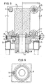
- the insert 11 is mounted on a rotator 40 and that on a, generally rectangular, turntable 13 which is rotatably mounted on an H-shaped base plate 14.
- the legs of the H reach close to the tool platens, as can be seen in Fig. 1 for the rear legs 15 and 16.
- additional guides can be provided on which the base plate is mounted and which can extend below the tool platens to outside of these.
- the legs of the H-shaped base plate are made wider or it is on one or both sides of the insert on the space between the legs of the H more or less strongly omitted and formed the base plate in this area throughout.
- One of the turntable 13 downwardly pointing pivot pin 19 (rotor) is rotatably mounted in a corresponding stator 20 and the base plate 14.
- the drive of the turntable by means of suitable drive means, for example by means of sprocket 43, pinion 44 and hydraulic or electric motor 49 (see Fig.5 and 6).
- the base plate 14 is mounted on stable linear guides 23 (or sliding guides) on the machine bed 2.
- the machine bed has stable linear rails or sliding guides 24 and 25, in which engages the correspondingly shaped underside of the base plate.
- finished molded parts can be ejected into the free space between the legs of the H and transported away from a conveyor belt (not shown here) arranged underneath. It thus eliminates additional handling systems for molding removal.
- transport straps 39 and eyebolts 38 (see Figure 3) is an easy installation and removal of the entire tool as a unit possible.
- the tool parts can also be installed and removed separately, if eyebolts 38 are present on each tool part and the transport straps 39 are released.
- one or more grooves and holes in the resting on the turntable part are provided in the lower region, so that fixing screws can be screwed through these holes in the turntable and the screw heads are accessible via the grooves.
- not shown in the turntable centering means are provided to align the tool center plate clean.
- a holding frame 45 ie a so-called index frame or a so-called index plate, may be provided for a molding 46 to permit rotation of this molding 46 from a first stroke to a second stroke between the tool halves 9 and 10.
Landscapes
- Engineering & Computer Science (AREA)
- Manufacturing & Machinery (AREA)
- Mechanical Engineering (AREA)
- Injection Moulding Of Plastics Or The Like (AREA)
- Moulds For Moulding Plastics Or The Like (AREA)
Claims (11)
- Presse d'injection horizontale avec une plaque de serrage d'outil fixe (3) et une plaque de serrage d'outil mobile (4), avec des longerons (5, 6, 7, 8) situés entre les deux plaques de serrage d'outil (3, 4) ainsi qu'avec un dispositif de rotation (40) pour outils d'injection, situé entre les plaques de serrage d'outil (3, 4) et mobiles parallèlement à l'axe longitudinal de la presse et un dispositif de rotation pour outils d'injection séparé des longerons (5, 6, 7, 8),
caractérisée en ce que
le dispositif de rotation (40) comporte une plaque de fond (14), en ce que un plateau tournant (13) est disposé en rotation autour d'un axe vertical monté sur la plaque de fond (14), en ce qu'une couronne dentée (43) est prévue sur le plateau tournant (13), et en ce qu'un moteur électrique ou hydraulique (49) est prévu pour entraîner le plateau tournant (13), une roue d'entraînement (44) pouvant être entraînée avec celui-ci, laquelle est en prise avec la couronne dentée (43)prévue sur le plateau tournant (13). - Presse d'injection horizontale selon la revendication 1, caractérisée en ce que, pour le déplacement du dispositif de rotation, celui-ci est couplé avec les deux plaques de serrage d'outil (3, 4), de telle sorte que, lors du déplacement de la plaque de serrage d'outil mobile (4), le dispositif de rotation est déplacé en même temps, par exemple grâce à des crémaillères (36, 37), des broches, en particulier des broches à pas rapide ou un vérin hydraulique.
- Presse d'injection horizontale selon la revendication 1, caractérisée en ce que le dispositif de rotation peut être déplacé indépendamment de la plaque de serrage d'outil mobile (4) parallèlement à l'axe longitudinal de la presse, par exemple à l'aide d'unités de vérins hydrauliques.
- Presse d'injection horizontale selon l'une quelconque des revendications 1 à 3, caractérisée en ce que, sur le plateau tournant (13), la partie centrale d'un outil étagé est fixée, la partie centrale étant par exemple une plaque centrale (11) ou un support de forme prismatique.
- Presse d'injection horizontale selon l'une quelconque des revendications 1 à 4, caractérisée en ce que la plaque de fond (14) est sensiblement en forme de H et en ce que l'élément transversal de la plaque de fond en forme de H et le plateau tournant sont configurés de telle sorte que des pièces formées puissent tomber vers le bas dans l'espace libre entre les montants (15, 16, 17, 18) du H.
- Presse d'injection horizontale selon la revendication 4 ou 5, caractérisée en ce qu'un ou plusieurs anneau(x) à vis (38) est (sont) prévu(s) sur la face supérieure de la partie centrale (11) et/ou de la moitié d'outil fixe (9) et/ou mobile (10).
- Presse d'injection horizontale selon l'une quelconque des revendications 4 à 6, caractérisée en ce qu'une ou plusieurs languette(s) de transport (39) est(sont) prévue(s) sur la face supérieure au-dessus de l'ensemble de l'outil, languettes avec lesquelles les parties d'outil peuvent être maintenues ensemble et montées et démontées en formant une unité.
- Presse d'injection horizontale selon l'une quelconque des revendications 1 à 7, caractérisée en ce que, sur le plateau tournant (13), des moyens sont prévus pour maintenir les pièces formées (49) produites par la moitié fixe et la moitié mobile d'un outil (47, 48) serré entre les plaques de serrage d'outil (3, 4), par exemple des barres de maintien ou un cadre de maintien (45).
- Presse d'injection horizontale selon l'une quelconque des revendications 1 à 8, caractérisée en ce que respectivement dans la zone des plans de séparation des moitiés formées sont prévus des vérins pousseurs hydrauliques (28 à 35), au moins deux, de préférence quatre vérins pousseurs étant prévus dans chaque plan de séparation.
- Presse d'injection horizontale selon l'une quelconque des revendications 1 à 9, caractérisée en ce que la plaque de fond (14) va aussi loin dans le sens longitudinal que, lorsque l'outil est fermé, il ne reste qu'un petit intervalle (intervalle de sécurité) avec chaque plaque de serrage d'outil (3, 4) de la presse d'injection horizontale.
- Presse d'injection horizontale selon l'une quelconque des revendications 1 à 10, caractérisée en ce que la plaque de fond (14) est aussi longue dans le sens longitudinal que, lorsque l'outil est fermé, elle passe sous les plaques de serrage d'outil (3, 4), jusqu'à la zone extérieure des plaques de serrage d'outil (3, 4).
Applications Claiming Priority (4)
| Application Number | Priority Date | Filing Date | Title |
|---|---|---|---|
| DE19937200 | 1999-08-06 | ||
| DE19937200A DE19937200B4 (de) | 1999-08-06 | 1999-08-06 | Dreheinrichtung für Horizontalspritzgießmaschinen |
| EP02012663A EP1264674B1 (fr) | 1999-08-06 | 2000-08-04 | Machine à mouler par injection horizontale |
| EP00953154A EP1119449B1 (fr) | 1999-08-06 | 2000-08-04 | Presse d'injection horizontale avec deux plateaux matrices |
Related Parent Applications (1)
| Application Number | Title | Priority Date | Filing Date |
|---|---|---|---|
| EP02012663A Division EP1264674B1 (fr) | 1999-08-06 | 2000-08-04 | Machine à mouler par injection horizontale |
Publications (3)
| Publication Number | Publication Date |
|---|---|
| EP1484153A2 EP1484153A2 (fr) | 2004-12-08 |
| EP1484153A3 EP1484153A3 (fr) | 2005-03-09 |
| EP1484153B1 true EP1484153B1 (fr) | 2007-12-26 |
Family
ID=7917482
Family Applications (3)
| Application Number | Title | Priority Date | Filing Date |
|---|---|---|---|
| EP00953154A Expired - Lifetime EP1119449B1 (fr) | 1999-08-06 | 2000-08-04 | Presse d'injection horizontale avec deux plateaux matrices |
| EP04017582A Expired - Lifetime EP1484153B1 (fr) | 1999-08-06 | 2000-08-04 | Machine à mouler par injection horizontale |
| EP02012663A Expired - Lifetime EP1264674B1 (fr) | 1999-08-06 | 2000-08-04 | Machine à mouler par injection horizontale |
Family Applications Before (1)
| Application Number | Title | Priority Date | Filing Date |
|---|---|---|---|
| EP00953154A Expired - Lifetime EP1119449B1 (fr) | 1999-08-06 | 2000-08-04 | Presse d'injection horizontale avec deux plateaux matrices |
Family Applications After (1)
| Application Number | Title | Priority Date | Filing Date |
|---|---|---|---|
| EP02012663A Expired - Lifetime EP1264674B1 (fr) | 1999-08-06 | 2000-08-04 | Machine à mouler par injection horizontale |
Country Status (6)
| Country | Link |
|---|---|
| US (3) | US6830448B2 (fr) |
| EP (3) | EP1119449B1 (fr) |
| AT (4) | ATE381984T1 (fr) |
| CA (1) | CA2346494C (fr) |
| DE (6) | DE19937200B4 (fr) |
| WO (1) | WO2001010624A1 (fr) |
Families Citing this family (37)
| Publication number | Priority date | Publication date | Assignee | Title |
|---|---|---|---|---|
| DE19937200B4 (de) * | 1999-08-06 | 2006-11-16 | Krauss-Maffei Kunststofftechnik Gmbh | Dreheinrichtung für Horizontalspritzgießmaschinen |
| DE10152394A1 (de) * | 2001-10-24 | 2003-05-08 | Krauss Maffei Kunststofftech | Dreheinrichtung für Horizontal-Spritzgießmaschinen |
| DE10152625A1 (de) | 2001-10-25 | 2003-05-08 | Krauss Maffei Kunststofftech | Verstellbare Dreheinrichtung für Horizontal-Spritzgießmaschinen |
| US6616441B1 (en) * | 2002-04-17 | 2003-09-09 | Van Dorn Demag Corporation | Aligning device for vertical injection molding machine |
| US20050156352A1 (en) * | 2002-06-21 | 2005-07-21 | Krauss-Maffei Kunststofftechnik Gmbh | Method of and apparatus for injection molding multicomponent fiber-reinforced molded parts |
| DE10227636A1 (de) * | 2002-06-21 | 2004-01-15 | Krauss-Maffei Kunststofftechnik Gmbh | Verfahren und Vorrichtung zum Herstellen mehrkomponentiger Kunststoff-Formteile |
| US20040119205A1 (en) * | 2002-10-11 | 2004-06-24 | Taylor's Industrial Services, Llc | Rotating turret molding machine and associated process |
| DE102004024731B4 (de) * | 2003-08-14 | 2008-02-21 | Adcuram Maschinenbauholding Gmbh | Spritzgießvorrichtung |
| DE10347638A1 (de) | 2003-10-09 | 2005-05-19 | Krauss-Maffei Kunststofftechnik Gmbh | Horizontal-Spritzgießmaschine mit Dreheinrichtung |
| EP2266774B1 (fr) | 2004-02-10 | 2013-11-27 | Foboha GmbH Formenbau | Dispositif pour mouler par injection des pieces en plastique |
| DE102004038852B4 (de) * | 2004-08-10 | 2006-06-29 | Webasto Ag | Spritzgießmaschine |
| DE102004050311B4 (de) * | 2004-10-15 | 2008-02-07 | Krauss Maffei Gmbh | Schließeinheit für ein Spritzgießmaschine mit Etagenwerkzeug |
| DE102004057164A1 (de) | 2004-11-26 | 2006-06-01 | Krauss-Maffei Kunststofftechnik Gmbh | Spritzgießmaschine |
| DE102005016239A1 (de) | 2005-04-08 | 2006-10-12 | Krauss-Maffei Kunststofftechnik Gmbh | Horizontalspritzgießmaschine mit Dreheinrichtung |
| DE102005016240A1 (de) * | 2005-04-08 | 2006-10-12 | Krauss-Maffei Kunststofftechnik Gmbh | Horizontalspritzgießmaschine mit einer verfahrbaren Dreheinrichtung für Formen von Spritzgießwerkzeugen |
| US7331777B2 (en) * | 2005-04-19 | 2008-02-19 | Owens Illinois Closure Inc. | Compression molding machine |
| US7481646B2 (en) * | 2005-06-17 | 2009-01-27 | Rexam Closure Systems Inc. | Compression molding machine |
| DE102006016200A1 (de) | 2006-04-06 | 2007-10-11 | Krauss-Maffei Kunststofftechnik Gmbh | Verfahren und Vorrichtung zur Herstellung von mehrkomponentigen Kunststoff-Formteilen |
| US7753668B2 (en) * | 2007-01-24 | 2010-07-13 | Husky Injection Molding Systems Ltd. | Platen assembly, molding system and method for platen orientation and alignment |
| DE102007060863B4 (de) | 2007-12-18 | 2014-10-02 | Kraussmaffei Technologies Gmbh | Verfahren zur Herstellung mehrkomponentiger Kunststoffkorken |
| WO2009080827A2 (fr) | 2007-12-24 | 2009-07-02 | Foboha Gmbh Formenbau | Dispositif de moulage par injection |
| US8469693B2 (en) * | 2010-08-24 | 2013-06-25 | Athena Automation Ltd. | Low profile stack mold carrier |
| DE102010054421B3 (de) * | 2010-12-14 | 2011-12-29 | Kraussmaffei Technologies Gmbh | Formwerkzeug für eine Spritzgießmaschine mit begehbarem Formzwischenraum und solchermaßen ausgestattete Spritzgießmaschine |
| US8920156B2 (en) * | 2011-11-15 | 2014-12-30 | Electroform Company | Support member for a rotatable platen and a mold in an injection molding machine |
| CN103187661A (zh) * | 2011-12-27 | 2013-07-03 | 鸿富锦精密工业(深圳)有限公司 | 连接器防松脱装置 |
| CH707711A2 (de) | 2013-03-15 | 2014-09-15 | Foboha Gmbh | Haltevorrichtung für einen drehbaren Formmittelteil in einer Spritzgiessvorrichtung. |
| JP2015071278A (ja) * | 2013-10-04 | 2015-04-16 | ファナック株式会社 | プラテン調整機構を有する射出成形機の型締装置 |
| CH709548A2 (de) | 2014-04-17 | 2015-10-30 | Foboha Gmbh | Spritzgiessvorrichtung. |
| US9339957B2 (en) | 2014-05-07 | 2016-05-17 | Athena Automation Ltd. | Stack mold support structure for an injection molding machine |
| DE112017002866T5 (de) * | 2016-06-08 | 2019-02-21 | Niigon Machines Ltd. | Spritzgießmaschine mit Drehvorrichtung |
| JP6441271B2 (ja) * | 2016-08-23 | 2018-12-19 | 株式会社名機製作所 | 金型回転式射出成形機および金型回転式射出成形機の金型交換方法 |
| PT3532261T (pt) | 2016-10-26 | 2021-10-18 | Foboha Gmbh | Dispositivo de fixação para sistema de torneamento |
| DE102021130687B3 (de) | 2021-11-23 | 2023-01-19 | Schreiber Kunststofftechnik GmbH & Co. KG | Mehrkomponenten-Spritzgießmaschine |
| DE202022102721U1 (de) | 2022-05-18 | 2022-05-25 | Schreiber Kunststofftechnik GmbH & Co. KG | Etagenwendegruppe für eine Mehrkomponenten-Spritzgießmaschine |
| DE102023132445A1 (de) * | 2023-11-21 | 2025-05-22 | Kraussmaffei Technologies Gmbh | Formschließeinheit für eine Spritzgießmaschine |
| CN118514263B (zh) * | 2024-06-17 | 2024-11-12 | 深圳市久亿精密模具有限公司 | 一种塑胶件的注塑成型装置 |
| CN119238887B (zh) * | 2024-11-29 | 2025-02-25 | 深圳市精钢兴精密工业有限公司 | 一种卧式注塑机 |
Family Cites Families (20)
| Publication number | Priority date | Publication date | Assignee | Title |
|---|---|---|---|---|
| US3838961A (en) * | 1972-01-03 | 1974-10-01 | Toshiba Machine Co Ltd | Injection-blow molding apparatus |
| DE2250002C2 (de) * | 1972-10-12 | 1982-02-04 | Karl 7298 Loßburg Hehl | Kunststoff- Spritzgießmaschine mit einer eine Spritzgießform aufnehmenden Formschließeinheit |
| US4330257A (en) * | 1979-11-15 | 1982-05-18 | Husky Injection Molding Systems, Inc. | Turret-type injection-molding machine |
| US4330287A (en) * | 1980-02-28 | 1982-05-18 | The Gates Rubber Company | Ribbed power transmission belt |
| US4307057A (en) * | 1980-06-13 | 1981-12-22 | Siebolt Hettinga | Method for aligning an injection mold with a nozzle at the mold injection station |
| US4786455A (en) * | 1981-02-23 | 1988-11-22 | The Continental Group, Inc. | Rotary injection turret and method of utilizing the same in the making of preforms |
| US4408981A (en) * | 1982-06-18 | 1983-10-11 | Husky Injection Molding Systems Inc. | Support for an intermediate platen of a stack mold |
| DE8509642U1 (de) * | 1985-03-30 | 1985-07-18 | Wörner, Alois, 7580 Bühl | Werkzeug mit Einhängeöse, insbesondere aus zwei Formhälften bestehende Spritzgießform |
| JPS6260618A (ja) * | 1985-09-11 | 1987-03-17 | Japan Steel Works Ltd:The | 射出積層成形装置 |
| DE3620175A1 (de) * | 1986-06-14 | 1987-12-17 | Kloeckner Ferromatik Desma | Spritzgiessmaschine mit mindestens zwei plastifizier- und einspritzeinheiten |
| IT1219271B (it) * | 1988-05-06 | 1990-05-03 | Adelio Grasselli | Perfezionamento relativo alle grandi presse per lo stampaggio ad iniezione di materiali termoplastici poliesteri ed elastomeri |
| IT1251694B (it) * | 1991-10-15 | 1995-05-19 | Marchesi S R L Flli | Macchina per lo stampaggio di materie plastiche, con due stampi simmetricamente posizionati. |
| JP2695348B2 (ja) * | 1992-04-28 | 1997-12-24 | 大日本印刷株式会社 | 射出成形同時絵付装置 |
| DE4480340C2 (de) * | 1993-12-29 | 1997-10-23 | Kobe Steel Ltd | Zwei-Lagen-Schaum-Spritzgießmaschine |
| US5817345A (en) * | 1996-03-06 | 1998-10-06 | Husky Injection Molding System Ltd. | Turrent article molding machine and method of use |
| US5772420A (en) * | 1996-12-16 | 1998-06-30 | Holmes; Henry T. | Greaseless mold carrier and alignment system |
| DE19733667C2 (de) * | 1997-08-04 | 2002-02-07 | Ferromatik Milacron Maschb Gmb | Vorrichtung zur Herstellung von Spritzgießartikeln aus mindestens zwei Kunststoffschmelzen |
| EP0922556A1 (fr) * | 1997-12-03 | 1999-06-16 | FOBOHA GmbH | Machine à mouler par injection avec des moules mobiles, dispositif de fixation ainsi que support de moule pour une telle machine à mouler par injection |
| US6218749B1 (en) * | 1998-11-30 | 2001-04-17 | Reliance Electric Technologies, Llc | Electric motor having rotor-embedded sensor |
| DE19937200B4 (de) * | 1999-08-06 | 2006-11-16 | Krauss-Maffei Kunststofftechnik Gmbh | Dreheinrichtung für Horizontalspritzgießmaschinen |
-
1999
- 1999-08-06 DE DE19937200A patent/DE19937200B4/de not_active Expired - Lifetime
-
2000
- 2000-08-04 DE DE20022466U patent/DE20022466U1/de not_active Expired - Lifetime
- 2000-08-04 CA CA002346494A patent/CA2346494C/fr not_active Expired - Lifetime
- 2000-08-04 AT AT04017582T patent/ATE381984T1/de active
- 2000-08-04 EP EP00953154A patent/EP1119449B1/fr not_active Expired - Lifetime
- 2000-08-04 AT AT02012663T patent/ATE349310T1/de active
- 2000-08-04 WO PCT/EP2000/007562 patent/WO2001010624A1/fr not_active Ceased
- 2000-08-04 DE DE50013910T patent/DE50013910D1/de not_active Expired - Lifetime
- 2000-08-04 DE DE50001236T patent/DE50001236D1/de not_active Expired - Lifetime
- 2000-08-04 DE DE20023625U patent/DE20023625U1/de not_active Expired - Lifetime
- 2000-08-04 EP EP04017582A patent/EP1484153B1/fr not_active Expired - Lifetime
- 2000-08-04 AT AT00953154T patent/ATE232445T1/de active
- 2000-08-04 DE DE50014884T patent/DE50014884D1/de not_active Expired - Lifetime
- 2000-08-04 EP EP02012663A patent/EP1264674B1/fr not_active Expired - Lifetime
-
2001
- 2001-04-06 US US09/829,209 patent/US6830448B2/en not_active Expired - Lifetime
- 2001-06-18 AT AT0048001U patent/AT4743U1/de not_active IP Right Cessation
-
2004
- 2004-07-28 US US10/902,648 patent/US7134869B2/en not_active Expired - Fee Related
-
2005
- 2005-12-07 US US11/295,978 patent/US7186113B2/en not_active Expired - Fee Related
Also Published As
| Publication number | Publication date |
|---|---|
| US20060088626A1 (en) | 2006-04-27 |
| CA2346494A1 (fr) | 2001-02-15 |
| ATE381984T1 (de) | 2008-01-15 |
| EP1264674B1 (fr) | 2006-12-27 |
| ATE349310T1 (de) | 2007-01-15 |
| EP1264674A3 (fr) | 2002-12-18 |
| EP1484153A3 (fr) | 2005-03-09 |
| EP1264674A2 (fr) | 2002-12-11 |
| US20010051193A1 (en) | 2001-12-13 |
| DE50001236D1 (de) | 2003-03-20 |
| DE19937200B4 (de) | 2006-11-16 |
| DE19937200A1 (de) | 2001-02-15 |
| DE20023625U1 (de) | 2005-02-24 |
| ATE232445T1 (de) | 2003-02-15 |
| EP1484153A2 (fr) | 2004-12-08 |
| US7134869B2 (en) | 2006-11-14 |
| DE20022466U1 (de) | 2001-09-27 |
| DE50013910D1 (de) | 2007-02-08 |
| AT4743U1 (de) | 2001-11-26 |
| EP1119449B1 (fr) | 2003-02-12 |
| WO2001010624A1 (fr) | 2001-02-15 |
| CA2346494C (fr) | 2008-05-27 |
| US6830448B2 (en) | 2004-12-14 |
| DE50014884D1 (de) | 2008-02-07 |
| US20050003040A1 (en) | 2005-01-06 |
| EP1119449A1 (fr) | 2001-08-01 |
| US7186113B2 (en) | 2007-03-06 |
Similar Documents
| Publication | Publication Date | Title |
|---|---|---|
| EP1264674B1 (fr) | Machine à mouler par injection horizontale | |
| EP1673208B1 (fr) | Machine de moulage par injection horizontale pourvue d'un dispositif tournant | |
| EP2229267B1 (fr) | Dispositif de moulage par injection et procede | |
| EP0895848B1 (fr) | Dispositif de fabrication d'articles moulés par injection d'au moins deux matières plastiques fondues | |
| EP2969461B1 (fr) | Dispositif de support pour une pièce centrale orientable dans un dispositif de moulage | |
| EP0722820B2 (fr) | Dispositif de fermeture de moule sans colonnes | |
| EP0183944B1 (fr) | Dispositif de montage et de serrage d'outillage dans une machine de moulage par injection | |
| DE3856347T2 (de) | Rotierende einspritzblasgiessvorrichtung | |
| EP3036077A1 (fr) | Machine de moulage par injection à plusieurs composants pourvue d'une partie centrale rotative | |
| EP0583718B1 (fr) | Machine à mouler des matières plastiques par injection | |
| EP0720525A1 (fr) | Unite de fermeture double d'une presse d'injection | |
| EP1802441B1 (fr) | Unite de fermeture destinee a une machine de moulage par injection comportant un moule a etages | |
| EP0620095A2 (fr) | Machine à mouler par injection, notamment machine à mouler par injection des matières plastiques | |
| EP1512512B1 (fr) | Appareil de moulage par injection | |
| AT398290B (de) | Spritzgiessmaschine | |
| EP3015242B1 (fr) | Machine a mouler par injection | |
| WO1997021529A1 (fr) | Dispositif de fermeture de moule pour une machine de moulage de matieres plastiques, notamment pour une presse d'injection | |
| DE3715121C2 (fr) | ||
| WO2006027093A1 (fr) | Machine de moulage par injection | |
| EP0428761A1 (fr) | Dispositif de fermeture de moules pour la fabrication d'objets en plastic | |
| AT12173U1 (de) | Schliesseinheit für eine spritzgiessmaschine | |
| DE6946390U (de) | Giessmaschine fuer kunststoffe mit auswerfervorrichtung | |
| DD278302A1 (de) | Zweifarben-spritzgiessmaschine |
Legal Events
| Date | Code | Title | Description |
|---|---|---|---|
| PUAI | Public reference made under article 153(3) epc to a published international application that has entered the european phase |
Free format text: ORIGINAL CODE: 0009012 |
|
| AC | Divisional application: reference to earlier application |
Ref document number: 1119449 Country of ref document: EP Kind code of ref document: P Ref document number: 1264674 Country of ref document: EP Kind code of ref document: P |
|
| AK | Designated contracting states |
Kind code of ref document: A2 Designated state(s): AT BE CH CY DE DK ES FI FR GB GR IE IT LI LU MC NL PT SE |
|
| PUAL | Search report despatched |
Free format text: ORIGINAL CODE: 0009013 |
|
| AK | Designated contracting states |
Kind code of ref document: A3 Designated state(s): AT BE CH CY DE DK ES FI FR GB GR IE IT LI LU MC NL PT SE |
|
| 17P | Request for examination filed |
Effective date: 20050909 |
|
| AKX | Designation fees paid |
Designated state(s): AT BE CH CY DE DK ES FI FR GB GR IE IT LI LU MC NL PT SE |
|
| GRAP | Despatch of communication of intention to grant a patent |
Free format text: ORIGINAL CODE: EPIDOSNIGR1 |
|
| RAP1 | Party data changed (applicant data changed or rights of an application transferred) |
Owner name: KRAUSS MAFFEI GMBH |
|
| GRAS | Grant fee paid |
Free format text: ORIGINAL CODE: EPIDOSNIGR3 |
|
| GRAA | (expected) grant |
Free format text: ORIGINAL CODE: 0009210 |
|
| AC | Divisional application: reference to earlier application |
Ref document number: 1119449 Country of ref document: EP Kind code of ref document: P Ref document number: 1264674 Country of ref document: EP Kind code of ref document: P |
|
| AK | Designated contracting states |
Kind code of ref document: B1 Designated state(s): AT BE CH CY DE DK ES FI FR GB GR IE IT LI LU MC NL PT SE |
|
| REG | Reference to a national code |
Ref country code: GB Ref legal event code: FG4D Free format text: NOT ENGLISH |
|
| RAP2 | Party data changed (patent owner data changed or rights of a patent transferred) |
Owner name: KRAUSMAFFEI TECHNOLOGIES GMBH |
|
| REG | Reference to a national code |
Ref country code: IE Ref legal event code: FG4D Free format text: LANGUAGE OF EP DOCUMENT: GERMAN |
|
| REG | Reference to a national code |
Ref country code: CH Ref legal event code: NV Representative=s name: KIRKER & CIE S.A. Ref country code: CH Ref legal event code: EP |
|
| REF | Corresponds to: |
Ref document number: 50014884 Country of ref document: DE Date of ref document: 20080207 Kind code of ref document: P |
|
| RAP2 | Party data changed (patent owner data changed or rights of a patent transferred) |
Owner name: KRAUSSMAFFEI TECHNOLOGIES GMBH |
|
| NLT2 | Nl: modifications (of names), taken from the european patent patent bulletin |
Owner name: KRAUSMAFFEI TECHNOLOGIES GMBH Effective date: 20080102 |
|
| NLT2 | Nl: modifications (of names), taken from the european patent patent bulletin |
Owner name: KRAUSSMAFFEI TECHNOLOGIES GMBH Effective date: 20080213 |
|
| PG25 | Lapsed in a contracting state [announced via postgrant information from national office to epo] |
Ref country code: SE Free format text: LAPSE BECAUSE OF FAILURE TO SUBMIT A TRANSLATION OF THE DESCRIPTION OR TO PAY THE FEE WITHIN THE PRESCRIBED TIME-LIMIT Effective date: 20080326 |
|
| ET | Fr: translation filed | ||
| PG25 | Lapsed in a contracting state [announced via postgrant information from national office to epo] |
Ref country code: FI Free format text: LAPSE BECAUSE OF FAILURE TO SUBMIT A TRANSLATION OF THE DESCRIPTION OR TO PAY THE FEE WITHIN THE PRESCRIBED TIME-LIMIT Effective date: 20071226 Ref country code: NL Free format text: LAPSE BECAUSE OF FAILURE TO SUBMIT A TRANSLATION OF THE DESCRIPTION OR TO PAY THE FEE WITHIN THE PRESCRIBED TIME-LIMIT Effective date: 20071226 |
|
| NLV1 | Nl: lapsed or annulled due to failure to fulfill the requirements of art. 29p and 29m of the patents act | ||
| GBV | Gb: ep patent (uk) treated as always having been void in accordance with gb section 77(7)/1977 [no translation filed] | ||
| PG25 | Lapsed in a contracting state [announced via postgrant information from national office to epo] |
Ref country code: ES Free format text: LAPSE BECAUSE OF FAILURE TO SUBMIT A TRANSLATION OF THE DESCRIPTION OR TO PAY THE FEE WITHIN THE PRESCRIBED TIME-LIMIT Effective date: 20080406 |
|
| PG25 | Lapsed in a contracting state [announced via postgrant information from national office to epo] |
Ref country code: PT Free format text: LAPSE BECAUSE OF FAILURE TO SUBMIT A TRANSLATION OF THE DESCRIPTION OR TO PAY THE FEE WITHIN THE PRESCRIBED TIME-LIMIT Effective date: 20080526 |
|
| REG | Reference to a national code |
Ref country code: IE Ref legal event code: FD4D |
|
| PG25 | Lapsed in a contracting state [announced via postgrant information from national office to epo] |
Ref country code: DK Free format text: LAPSE BECAUSE OF FAILURE TO SUBMIT A TRANSLATION OF THE DESCRIPTION OR TO PAY THE FEE WITHIN THE PRESCRIBED TIME-LIMIT Effective date: 20071226 Ref country code: IE Free format text: LAPSE BECAUSE OF FAILURE TO SUBMIT A TRANSLATION OF THE DESCRIPTION OR TO PAY THE FEE WITHIN THE PRESCRIBED TIME-LIMIT Effective date: 20071226 |
|
| PLBE | No opposition filed within time limit |
Free format text: ORIGINAL CODE: 0009261 |
|
| STAA | Information on the status of an ep patent application or granted ep patent |
Free format text: STATUS: NO OPPOSITION FILED WITHIN TIME LIMIT |
|
| 26N | No opposition filed |
Effective date: 20080929 |
|
| PG25 | Lapsed in a contracting state [announced via postgrant information from national office to epo] |
Ref country code: GB Free format text: LAPSE BECAUSE OF FAILURE TO SUBMIT A TRANSLATION OF THE DESCRIPTION OR TO PAY THE FEE WITHIN THE PRESCRIBED TIME-LIMIT Effective date: 20071226 |
|
| PG25 | Lapsed in a contracting state [announced via postgrant information from national office to epo] |
Ref country code: GR Free format text: LAPSE BECAUSE OF FAILURE TO SUBMIT A TRANSLATION OF THE DESCRIPTION OR TO PAY THE FEE WITHIN THE PRESCRIBED TIME-LIMIT Effective date: 20080327 |
|
| PG25 | Lapsed in a contracting state [announced via postgrant information from national office to epo] |
Ref country code: MC Free format text: LAPSE BECAUSE OF NON-PAYMENT OF DUE FEES Effective date: 20080831 |
|
| PG25 | Lapsed in a contracting state [announced via postgrant information from national office to epo] |
Ref country code: BE Free format text: LAPSE BECAUSE OF NON-PAYMENT OF DUE FEES Effective date: 20080831 Ref country code: CY Free format text: LAPSE BECAUSE OF FAILURE TO SUBMIT A TRANSLATION OF THE DESCRIPTION OR TO PAY THE FEE WITHIN THE PRESCRIBED TIME-LIMIT Effective date: 20071226 |
|
| REG | Reference to a national code |
Ref country code: AT Ref legal event code: HC Ref document number: 381984 Country of ref document: AT Kind code of ref document: T Owner name: KRAUSSMAFFEI TECHNOLOGIES GMBH, DE Effective date: 20121116 |
|
| REG | Reference to a national code |
Ref country code: DE Ref legal event code: R082 Ref document number: 50014884 Country of ref document: DE Representative=s name: WILHELM, LUDWIG, DIPL.-PHYS., DE |
|
| REG | Reference to a national code |
Ref country code: DE Ref legal event code: R081 Ref document number: 50014884 Country of ref document: DE Owner name: KRAUSSMAFFEI TECHNOLOGIES GMBH, DE Free format text: FORMER OWNER: KRAUSMAFFEI TECHNOLOGIES GMBH, 80997 MUENCHEN, DE Effective date: 20130603 Ref country code: DE Ref legal event code: R082 Ref document number: 50014884 Country of ref document: DE Representative=s name: WILHELM, LUDWIG, DIPL.-PHYS., DE Effective date: 20130603 |
|
| PGFP | Annual fee paid to national office [announced via postgrant information from national office to epo] |
Ref country code: LU Payment date: 20130822 Year of fee payment: 14 |
|
| PG25 | Lapsed in a contracting state [announced via postgrant information from national office to epo] |
Ref country code: LU Free format text: LAPSE BECAUSE OF NON-PAYMENT OF DUE FEES Effective date: 20140804 |
|
| REG | Reference to a national code |
Ref country code: AT Ref legal event code: PC Ref document number: 381984 Country of ref document: AT Kind code of ref document: T Owner name: KRAUSSMAFFEI TECHNOLOGIES GMBH, DE Effective date: 20160706 |
|
| REG | Reference to a national code |
Ref country code: FR Ref legal event code: PLFP Year of fee payment: 17 |
|
| REG | Reference to a national code |
Ref country code: FR Ref legal event code: PLFP Year of fee payment: 18 |
|
| REG | Reference to a national code |
Ref country code: FR Ref legal event code: PLFP Year of fee payment: 19 |
|
| PGFP | Annual fee paid to national office [announced via postgrant information from national office to epo] |
Ref country code: GB Payment date: 20180625 Year of fee payment: 15 Ref country code: IT Payment date: 20180830 Year of fee payment: 19 |
|
| PGFP | Annual fee paid to national office [announced via postgrant information from national office to epo] |
Ref country code: CH Payment date: 20180822 Year of fee payment: 19 |
|
| PGFP | Annual fee paid to national office [announced via postgrant information from national office to epo] |
Ref country code: DE Payment date: 20190822 Year of fee payment: 20 |
|
| PGFP | Annual fee paid to national office [announced via postgrant information from national office to epo] |
Ref country code: AT Payment date: 20190822 Year of fee payment: 20 |
|
| PG25 | Lapsed in a contracting state [announced via postgrant information from national office to epo] |
Ref country code: CH Free format text: LAPSE BECAUSE OF NON-PAYMENT OF DUE FEES Effective date: 20190831 Ref country code: LI Free format text: LAPSE BECAUSE OF NON-PAYMENT OF DUE FEES Effective date: 20190831 |
|
| PG25 | Lapsed in a contracting state [announced via postgrant information from national office to epo] |
Ref country code: FR Free format text: LAPSE BECAUSE OF NON-PAYMENT OF DUE FEES Effective date: 20190831 |
|
| REG | Reference to a national code |
Ref country code: DE Ref legal event code: R071 Ref document number: 50014884 Country of ref document: DE |
|
| PG25 | Lapsed in a contracting state [announced via postgrant information from national office to epo] |
Ref country code: IT Free format text: LAPSE BECAUSE OF NON-PAYMENT OF DUE FEES Effective date: 20190804 |
|
| REG | Reference to a national code |
Ref country code: AT Ref legal event code: MK07 Ref document number: 381984 Country of ref document: AT Kind code of ref document: T Effective date: 20200804 |