EP1484201B1 - Actionneur avec du filtre pour interference electromagnetique - Google Patents
Actionneur avec du filtre pour interference electromagnetique Download PDFInfo
- Publication number
- EP1484201B1 EP1484201B1 EP04102426A EP04102426A EP1484201B1 EP 1484201 B1 EP1484201 B1 EP 1484201B1 EP 04102426 A EP04102426 A EP 04102426A EP 04102426 A EP04102426 A EP 04102426A EP 1484201 B1 EP1484201 B1 EP 1484201B1
- Authority
- EP
- European Patent Office
- Prior art keywords
- actuator
- power
- filter board
- switching devices
- filter
- Prior art date
- Legal status (The legal status is an assumption and is not a legal conclusion. Google has not performed a legal analysis and makes no representation as to the accuracy of the status listed.)
- Expired - Lifetime
Links
- 239000003990 capacitor Substances 0.000 claims description 56
- 239000000725 suspension Substances 0.000 claims description 18
- 239000000919 ceramic Substances 0.000 claims description 5
- 230000000694 effects Effects 0.000 claims description 3
- 239000010408 film Substances 0.000 claims description 3
- 239000004743 Polypropylene Substances 0.000 claims description 2
- 239000011104 metalized film Substances 0.000 claims description 2
- 229920006289 polycarbonate film Polymers 0.000 claims description 2
- 229920006267 polyester film Polymers 0.000 claims description 2
- -1 polypropylene Polymers 0.000 claims description 2
- 229920001155 polypropylene Polymers 0.000 claims description 2
- 230000001419 dependent effect Effects 0.000 claims 2
- 238000013016 damping Methods 0.000 description 15
- POIUWJQBRNEFGX-XAMSXPGMSA-N cathelicidin Chemical compound C([C@@H](C(=O)N[C@@H](CCCNC(N)=N)C(=O)N[C@@H](CCCCN)C(=O)N[C@@H](CO)C(=O)N[C@@H](CCCCN)C(=O)N[C@@H](CCC(O)=O)C(=O)N[C@@H](CCCCN)C(=O)N[C@@H]([C@@H](C)CC)C(=O)NCC(=O)N[C@@H](CCCCN)C(=O)N[C@@H](CCC(O)=O)C(=O)N[C@@H](CC=1C=CC=CC=1)C(=O)N[C@@H](CCCCN)C(=O)N[C@@H](CCCNC(N)=N)C(=O)N[C@@H]([C@@H](C)CC)C(=O)N[C@@H](C(C)C)C(=O)N[C@@H](CCC(N)=O)C(=O)N[C@@H](CCCNC(N)=N)C(=O)N[C@@H]([C@@H](C)CC)C(=O)N[C@@H](CCCCN)C(=O)N[C@@H](CC(O)=O)C(=O)N[C@@H](CC=1C=CC=CC=1)C(=O)N[C@@H](CC(C)C)C(=O)N[C@@H](CCCNC(N)=N)C(=O)N[C@@H](CC(N)=O)C(=O)N[C@@H](CC(C)C)C(=O)N[C@@H](C(C)C)C(=O)N1[C@@H](CCC1)C(=O)N[C@@H](CCCNC(N)=N)C(=O)N[C@@H]([C@@H](C)O)C(=O)N[C@@H](CCC(O)=O)C(=O)N[C@@H](CO)C(O)=O)NC(=O)[C@H](CC=1C=CC=CC=1)NC(=O)[C@H](CC(O)=O)NC(=O)CNC(=O)[C@H](CC(C)C)NC(=O)[C@@H](N)CC(C)C)C1=CC=CC=C1 POIUWJQBRNEFGX-XAMSXPGMSA-N 0.000 description 8
- 238000010586 diagram Methods 0.000 description 6
- 238000004806 packaging method and process Methods 0.000 description 6
- 230000001133 acceleration Effects 0.000 description 4
- 230000035945 sensitivity Effects 0.000 description 2
- 239000006096 absorbing agent Substances 0.000 description 1
- 238000004891 communication Methods 0.000 description 1
- 238000004146 energy storage Methods 0.000 description 1
- 230000007613 environmental effect Effects 0.000 description 1
- 238000001914 filtration Methods 0.000 description 1
- 230000010354 integration Effects 0.000 description 1
- 238000002955 isolation Methods 0.000 description 1
- 239000002184 metal Substances 0.000 description 1
- 230000007935 neutral effect Effects 0.000 description 1
- 230000003071 parasitic effect Effects 0.000 description 1
- 230000001105 regulatory effect Effects 0.000 description 1
- 230000035939 shock Effects 0.000 description 1
- 230000001052 transient effect Effects 0.000 description 1
- 238000004804 winding Methods 0.000 description 1
Images



Classifications
-
- B—PERFORMING OPERATIONS; TRANSPORTING
- B60—VEHICLES IN GENERAL
- B60G—VEHICLE SUSPENSION ARRANGEMENTS
- B60G17/00—Resilient suspensions having means for adjusting the spring or vibration-damper characteristics, for regulating the distance between a supporting surface and a sprung part of vehicle or for locking suspension during use to meet varying vehicular or surface conditions, e.g. due to speed or load
- B60G17/015—Resilient suspensions having means for adjusting the spring or vibration-damper characteristics, for regulating the distance between a supporting surface and a sprung part of vehicle or for locking suspension during use to meet varying vehicular or surface conditions, e.g. due to speed or load the regulating means comprising electric or electronic elements
-
- H—ELECTRICITY
- H03—ELECTRONIC CIRCUITRY
- H03H—IMPEDANCE NETWORKS, e.g. RESONANT CIRCUITS; RESONATORS
- H03H7/00—Multiple-port networks comprising only passive electrical elements as network components
- H03H7/01—Frequency selective two-port networks
- H03H7/0115—Frequency selective two-port networks comprising only inductors and capacitors
-
- H—ELECTRICITY
- H04—ELECTRIC COMMUNICATION TECHNIQUE
- H04B—TRANSMISSION
- H04B15/00—Suppression or limitation of noise or interference
- H04B15/02—Reducing interference from electric apparatus by means located at or near the interfering apparatus
- H04B15/025—Reducing interference from ignition apparatus of fuel engines
Definitions
- This invention relates to an actuator having an electromagnetic interference (EMI) filter.
- EMI electromagnetic interference
- a prior art actuator according to the preamble of claim 1 is known from EP 0 415 780 A .
- Active automotive suspensions can include electrically powered actuators.
- power is supplied to the suspension, such as to help control vertical accelerations of a sprung mass when an unsprung mass encounters road disturbances.
- Integrating power electronics within an actuator can result in unacceptable levels of conducted electromagnetic interference (EMI).
- EMI conducted electromagnetic interference
- the invention features an electromechanical actuator, for a vehicle suspension system, including a housing having a first section adapted to affix to a vehicle body and a second section adapted to affix to a vehicle wheel assembly suspended to the vehicle body, the first and second sections coupled to form a motor, electronics including power-switching devices disposed within a chamber of the housing and adapted to receive electrical power and to direct power to the motor, and a filter board disposed within the chamber and connected to the electronics, in use, between the electronics and an external direct current (DC) power source.
- DC direct current
- the filter board may include capacitors and inductors disposed within the chamber to suppress electromagnetic emissions generated by the power-switching devices conducted to an external DC power source.
- the motor can be a linear or rotary motor.
- the power-switching devices can be single-phase or multi-phase switching devices.
- the suppressed noise can be conducted emissions.
- the chamber can reduce radiated emissions from the power-switching devices.
- the DC power source can provide power which meets a variety of specifications such as having average voltage substantially equal to 325 volts, or greater than 12 volts, or greater than 42 volts, or greater than 118 volts, having peak current greater than 75 amps or substantially 100 amps, or having peak power substantially equal to or greater than 30 KW.
- the filter board can be designed to fit within a package having a predetermined volume, which can be less than 2,100,000 cubic millimeters.
- the capacitors can be non-electrolytic capacitors (ceramic and DC Film type) such as disk ceramics, monolithic/multilayer ceramics, polyester film, polycarbonate film, polypropylene film and metalized films, and so forth.
- the filter board can distribute capacitance while keeping line transients to a minimum.
- the filter board can have an output impedance less than 1 ohm for frequencies within a 0 Hz to 2 kHz range.
- the filter board can have an output impedance less than 1 ohm for frequency within a 15 kHz to 5 MHz range.
- the filter board includes a multi-section ladder filter with dampening resistance designed for a package having a predetermined volume.
- the multi-section ladder filter can include capacitors and inductors.
- the multi -section ladder filter can include a dampening mechanism.
- the dampening mechanism can parallelly connect a resistance to at least one of the inductors.
- the dampening mechanism can serially connect a resistance to at least one of the capacitors.
- the multi -section ladder filter can include a dominant inductance serially connected to the power supply line.
- the dampening mechanism can parallelly connect a resistance to the dominant inductance to damp inductor-capacitor resonances that occur between the line inductance and a supply decoupling capacitance to protect the switching power devices and reduce the conducted and radiated EMI emissions.
- the dampening mechanism can also parallelly connect a link composed of a dampening resistance serially connected to a dampening capacitor, in parallel to at least one of the capacitors of the multi-section ladder filter.
- the filter board has a cutoff frequency designed to facilitate the power-switching devices to switch at a predetermined switching frequency.
- the predetermined switching frequency can be greater than audible frequencies such as 15 kilohertz (kHz).
- Capacitors and inductors can provide a predetermined attenuation to the power-switching devices output signals (and to the external DC power source signals) having frequency components greater than 520 kHz.
- the predetermined attenuation can be at least 120 decibels (dB).
- the filter board is designed to have specific vibration tolerance characteristics.
- the vibration tolerance characteristics can follow Society of Automotive Engineers (SAE) J1211 recommendations.
- the filter board is designed to meet specific EMI emissions specifications.
- the specific EMI emissions specifications can be as defined in Society of Automotive Engineers (SAE) J551 and J1113.
- the filter board has a power density of at least 0.0143 watts/cubic millimeter disposed within the chamber to suppress noise generated by the power-switching devices to an external DC power source.
- the suppressed noise c an be conducted emissions.
- the filter board has a mass density substantially 0.0000007 kg per cubic millimeter disposed within the chamber to suppress noise generated by the power-switching devices to an external DC power source.
- the s uppressed noise can be conducted emissions.
- the filter board comprises a large inductor positioned between the external power supply and the power-switching devices by the power supply line.
- the large inductor can have dominant inductance relative to the power supply line.
- the large inductor can minimize the negative effects of the power line inductance to allow the power-switching devices to be located freely within the actuator.
- Embodiments of the invention can have one or more of the following advantages.
- a filter board including capacitors and inductors, disposed within a chamber of an electromechanical actuator of an active vehicle suspension system, suppresses noise generated by power-switching devices to an external DC power so urce.
- a filter board is disposed within a chamber of an electromechanical actuator in an active vehicle suspension system and is designed as a multi -section ladder filter with dampening resistance for a package having a predetermined volume.
- a filter board is disposed within a chamber of an electromechanical actuator in an active vehicle suspension system and positioned between power-switching devices and an external DC power source, the filter board cutoff frequency is designed to facilitate the power-switching devices to switch at a predetermined switching frequency.
- a filter board is disposed within a chamber of an electromechanical actuator in an active vehicle suspension system that follows specific vibration tolerance recommendations.
- the filter board is designed to a specific power density for the power electronics within the active vehicle suspension system.
- the filter board facilitates the integration of power electronics into an actuator. By doing so, besides cost and size benefits due to small packaging, switching phase currents are contained in a housing and travel along much shorter cables, thus reducing radiated EMI emissions.
- the high order multi-section ladder EMI filter reduces the capacitance requirements and further facilitates packaging by allowing distribution of the capacitance while keeping line transients to a minimum and therefore minimizing conducted and radiated EMI emissions.
- an active electromechanical suspension system power is supplied to an electromechanical suspension to help control vertical accelerations of the sprung mass when the unsprung mass encounters road disturbances.
- the shock absorber of a common suspension can be replaced by a con trolled force actuator that responds according to commands from a control system.
- the actuator can be electrically powered.
- High electrical current requirements for supplying the necessary power to an active vehicle suspension system can generate undesirable electromagnetic interference (EMI) that can interfere with radio reception and electrical devices in the vehicle.
- EMI undesirable electromagnetic interference
- packaging of an electrical actuator capable of developing the forces and speeds required to perform adequately as an active sus pension actuator in the space available can be difficult.
- a system 10 includes active vehicle suspension actuator 12.
- the actuator 12 includes an armature 14 slidable with respect to a stator 16.
- Stator 16 is attachable to an end of a top cap 18, which is a metallic housing that defines an internal cavity and can have, for example, an oval cross section.
- Top cap 18 further affixes to a vehicle body 20.
- top cap 18 Housed within the top cap 18 are on-board power electronics 24 and a filter board 26. More specifically, power electronics 24 and filter board 26 are attached to top cap 18 and positioned inside top cap 18 in cavities defined by top cap 18 and armature 14 such that the power electronics 24 and filter board 26 do not interfere with armature 14 moving relative to stator 16.
- the actuator 14 includes an electronic motor (armature 14 and stator 16) that converts electrical energy into mechanical work.
- the linear electronic motor with appropriate communication controls, provides a controllable force between the wheel assembly 22 and the vehicle body 20. Any variation in force that is desired can be produced by correspondingly varying a control signal.
- armature 14 and stator 16 such as those described in U. S. Patent 5,574,445 (Maresca et al. ) for a linear motor, incorporated herein by reference in its entirety.
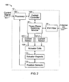
- FIG. 2 a function block diagram 100 of the actuator 12 having integrated power electronics 24 and EMI (Electromagnetic Interference) filter board 26 is shown.
- a control signal 101 such as an external analog or digital command signal from a central controller as shown or an internal control signal from the actuator 14 (not shown), i s utilized to command the integrated actuator 12 to generate electrically controllable force between the sprung and unsprung masses.
- Active suspension actuator 12 is electrically controlled by a processor 102.
- the processor 102 commands single-phase or multiple-phase power-switching electronics 24.
- the current controller 104 controls the phase currents that excite the linear motor (shown as actuator coils 108).
- actuator coils 108 For the illustrated three -phase power-switching electronics 24, a basic function of the current controller 104 is to close a feedback loop in current for two of the phases and constrain the voltage of the third phase so that the internal neutral remains near zero voltage.
- the three-phase power-switching electronics 24 can be, for example, a BSM 150 GD 18 DLC manufactured by Eupec Corporation.
- the power electronics 24 contains power-switching devices that apply voltage to the actuator coils.
- the actuator 12 includes multiple permanent magnets 110 (mounted on armature 14).
- the moving field is produced by the stator's 16 stationary windings (shown as actuator coils 108), whose three phases are commutated in the proper sequence. This sequence is governed by the position /velocity /acceleration of the magnets 110. This information is provided by the position sensor 112.
- processor 102 and current controller 104 include deriving the proper switching logic sequence and commutation for the power-switching devices contained in power-switching module 24.
- the processor 102 provides a controllable force with respect to the position /velocity /acceleration of the actuator magnets 110 within its range of operation by providing current commands to the current controller 104, which further controls the three-phase switching module 24 that creates individual phase currents to drive actuator coils 108.
- the current sensors 107-1 and 107-2 are used to monitor the currents.
- the stator 16 (shown as actuator coils 108) interacts with armature 14 (shown as actuator magnets 110) to provide the desired force.
- EMI filter board 26 is used between the external DC power line 114 and the power-switching module 24.
- Actuator 14 uses power whenever it generates force.
- the power is provided by one or more power sources including a generator, which can be used to provide power when actuator 14 operates under a low power condition. Additionally, a battery system and one or more energy storage devices, such as capacitors, can provide additional power when the actuator 14 operates under conditions th at require higher power.
- the external power source can provide power which meets a variety of specifications, such as having average voltage substantially equal to 325 volts, or greater than 12 volts, or greater than 42 volts, or greater than 118 volts or having peak current greater than 75 amps or substantially 100 amps, or having peak power substantially equal to or greater than 30 KW, depending on the specific application requirements and power electronics 24 implementations.
- a high-value capacitor, C is used as a filter between the power supply 114 and the power-switching devices 24. Capacitor values on the order of several thousand microfarads are typical. Since the power supply line 114 has some parasitic inductance, L, the high-value capacitor reduces the L-C resonance seen by the power-switching devices 24 and attenuates conducted EMI emissions.
- using a high - valued capacitor is problematic for at least two reasons. First, high -value, high-voltage capacitors are physically large. Therefore, it can be difficult, or impossible, to package the capacitor into the volume available in the actuator housing. Second, high -value capacitors are typically electrolytic-type, which have limited environmental capability, especially with respect to the vibration and temperature extremes required in an automotive application.
- FIG. 3 a schematic diagram 200 of the filter board 26 is shown.
- a power source 202 provides power to an integrated actuator 204 via power line wire 206.
- the power source 202 can include a generator 208, a battery system 210, and one or more capacitors 212.
- the cable wire 206 has line inductance value L -wire 214.
- the filter board 26 is designed to meet a variety of specifications and constraints as described below.
- a low impedance from the filter board 26 ensures that a substantial amount of the power transferred through the filter board 26 is delivered to the switching modules 24 and not dissipated in the filter 26 itself.
- the power-switching module 24, which commands the motor 230 can be designed to operate at different t switching frequencies. For example, it can be desirable to switch at frequencies above the audible range, such as 15 to 20KHz.
- the filter board 26 reduces the conducted EMI emissions generated by the power-switching module 24 that are transmitted back onto the external power line 206.
- the intensity of the EMI emissions is regulated by government agencies in many countries to prevent interference with other equipment.
- SAE Society of Automotive Engineers
- EMC Electromagnetic Compatibility
- SAE J551 and J1113 provide EMI specifications.
- the filter board 26 also should suppress power supply transients entering from the power line 206 from affecting the power-switching module 24. Without proper filtering, such transients can cause the power-switching module 24 to fail.
- the filter board 26 and power electronics 24 combination should fit into the available space inside the actuator housing.
- the space available inside the actuator housing for packaging board and power electronics combination can be less than 2,100,000 cubic millimeters (cm).
- the power density defined as peak power per cubic millimeter for the exemplary actuator with integrated filter board 26 and power electronics 24 is at least 0.0143 watts/cubic millimeter (30KW/2100000 cubic millimeters).
- the mass density defined as kilograms of electronics per cubic millimeter is substantially 0.0000007 kg per cubic millimeter (1.5kg mass /2100000 cubic millimeters).
- a multi-stage L-C (i.e., inductor-capacitor) filter ladder with damping resistor 216 is used. Since a single L-C section provides a second-order low pass filter effect, a higher-order multi-section ladder filter created by cascading several L-C sections together achieves significant attenuation (isolation) at the frequencies of interest. Thus, a conducted EMI emissions design requirement can be met.
- the order of a filter is the number of poles in the transfer function, which can be estimated from the number of reactive elements (capacitors and inductors) the filter contains.
- the first stage of the filter 26 has a dominant inductor 218 (whose value is large relative to the power line inductance value L-wire 214) and a capacitor 220.
- a damping resistor 216 is parallel-connected to the dominant inductor 218.
- the remaining two stages include an inductor (226 for stage 2 and 228 for stage 3) and a capacitor (222 for stage 2 and 224 for stage 3).
- the use of dominant inductor 218 in the first stage serves to minimize the sensitivity of the EMI filter 26 to power line inductance L-wire 214. Minimizing the sensitivity to power line inductance allows the actuator to be located remotel y from power supply 202 and eases the design constraint of power supply line length.
- damping resistor 216 serves to reduce resonances in the filter 26.
- a typical L-C section is an under-damped resonant circuit, which can lead to transient peaking at the power-switching module 24. These transients can damage the power-switching module 24, which makes damping necessary.
- Damping resistor 216 serves to damp these resonances, which causes conducted and radiated EMI emissions from the power electronics 24 and filter board 26 to be reduced. In addition, damping resistor 216 ensures that no damaging transients are presented to the power-switching module.
- FIG. 4 shows a damping resistor R parallel-connected to the inductor L, (b) shows a damping resistor R series-connected to the capacitor C. Other choices that can not be as efficient as (a) and (b) are shown in (c) where a damping resistor R is series-connected to the inductor L and (d) where a damping resistor R is parallel-connected to the capacitor C. As shown in FIG. 3 , a damping resistance 216 is parallel-connected to the dominant inductor 218.
- dampening resistance can also be serially connected to a dampening capacitor to construct a link, the link further parallelly connected to at least one of the capacitors of the multi-section ladder filter.
- the capacitance of the dampening capacitor is smaller than the capacitance of the capacitors of the multi-section ladder filter.
- circuit 26 shows three inductors 218, 226, 228 and three capacitors 220, 222, 224, depending on system requirements, there can be more or less inductors and capacitors used. Thus, the order of the filter board 26 can be different. The combinations of the configurations discussed above in FIG. 4 can also be used to provide damping.
- the multi-section filter board 26 can be designed to meet a variety of specifications such as the attenuation for certain frequency ranges, cutoff frequencies, output impedance, damping function, and so forth, by properly choosing the design parameters such as the number of stages (the ord er of the filter board) and the values of the components (capacitors, inductors, resistors).
- the inductor and capacitor values can be chosen such that the conducted EMI emissions meet the design specification as those defined in SAE J551 and J1113 and vibration tolerance characteristics follow those recommended in SAE J1211.
- the inductor, capacitor, and resistor values can be chosen such that the output impedance of the filter is suitable for the power-switching module.
- FIG. 5(a) is the real part of the output impedance of the exemplary filter board (Re(( V 1 - V 2 ) / I 2)) (as in FIG.3 ), and FIG. 5(b) is the magnitude of the current transfer function (frequency response) of the exemplary filter board (
- the output impedance of the filter board 26 is kept low to avoid unnecessary loss.
- a set of design specifications for the output impedance of the filter board 26 is such that the output impedance of the filter board 26 is less than 1 ohm during certain frequency ranges, such as for frequencies between 0 and 2KHz and between 15 kHz and 5 MHz. This ensures that the filter 26 provides a low impedance source at those frequencies where significant power is delivered and at the switching frequency (and harmonics).
- the actual inductors used to implement the filter 26 can be realized using combinations of series and parallel-connected inductors.
- the actual capacitors used to implement the filter 26 can be realized using combinations of series and parallel-connected capacitors.
- the actual resistors used to implement the filter 26 can be realized using combinations of series and parallel-connected resistors.
- FIG. 6 the multi-section filter board components that meet the filter design specifications as shown in FIG. 5(a) and (b) are shown.
- Each inductor on the filter board is a 4.7uH, 100 Amp inductor manufactured by Renco Electronics of Rockledge, Florida.
- the dominant inductor 218 includes four of these 4.7uH inductors in series, to generate a total inductance of approximately 20uH.
- Inductors 226 and 228 are each approximately 5.0uH inductors.
- the parallel-connected resistor 216 is a 0.4 Ohm resistor. For power dissipation purposes, resistor 216 can be realized using multiple parallel-connected resistors.
- Capacitors 220, 222 and 224 include parallel-connected 1uF, 400V capacitors manufactured by ITW Paktron of Bolingbrook, IL. Three 1uF parallel-connected capacitors make up the 3uF capacitance of capacitors 220 and 222. The 20uF capacitance of capacitor 224 is made up of twenty 1uF parallel-connected capacitors.
- FIG. 7 an exemplary layout 300 of the actuator 12 of FIG. 1 , which further shows one possible layout of the power-switching module 24 and the filter board 26 within the actuator housing, is shown.
- the filter board 26, loc ated within the actuator top cap 18 as shown in FIG. 1 includes inductors 218, 226 and 228, capacitors 220 and 222, resistor 216, and connects to the external DC power supply via the power supply line 206.
- the filter board 26 further connects to the power-switching module 24 via the wires 330.
- the processor 102, current control circuit 104, and power-switching module 24 are also located within the actuator top cap 18 (labeled as "Control Circuit" in FIG. 7 ).
- FIG. 7 also shows the two current sensors 107-1 and 107-2 that connect to the actuator coils 108 within the stator 16.
- the armature 14 having a number of magnets slides relative to the stator 16.
Landscapes
- Engineering & Computer Science (AREA)
- Computer Networks & Wireless Communication (AREA)
- Signal Processing (AREA)
- Mechanical Engineering (AREA)
- Power Engineering (AREA)
- Filters And Equalizers (AREA)
- Vehicle Body Suspensions (AREA)
- Electric Propulsion And Braking For Vehicles (AREA)
- Vibration Prevention Devices (AREA)
- Shielding Devices Or Components To Electric Or Magnetic Fields (AREA)
- Inverter Devices (AREA)
- Arrangement Or Mounting Of Propulsion Units For Vehicles (AREA)
Claims (46)
- Actionneur électromécanique pour un système de suspension d'un véhicule, lequel actionneur comprend :un logement qui présente une première partie conçue pour s'attacher au corps d'un véhicule et une deuxième partie conçue pour s'attacher à un ensemble de roue de véhicule suspendu au corps du véhicule, la première partie et la deuxième partie étant reliées pour former un moteur, caractérisé en ce que :des dispositifs électroniques comprenant des dispositifs de commutation sont placés dans une chambre du logement et sont conçus pour recevoir de l'énergie électrique et pour diriger l'énergie vers le moteur, etune carte de filtrage est placé dans la chambre, est en utilisation relié aux dispositifs électroniques et est raccordé entre les dispositifs électroniques et une source d'énergie externe à courant continu (DC).
- Actionneur selon la revendication 1, comprenant des condensateurs et des inductances placés dans la chambre pour diminuer le bruit généré par les dispositifs de commutation raccordés à une source d'énergie externe à courant continu (DC).
- Actionneur selon la revendication 1 ou la revendication 2, dans lequel la carte de filtrage est conçu pour diminuer le bruit qui présente la forme d'interférences électromagnétiques (EMI) transmises par conduction.
- Dispositif selon l'une quelconque des revendications 1 à 3, dans lequel la chambre diminue les émissions transmises par les dispositifs de commutation.
- Actionneur selon l'une quelconque des revendications 1 à 4, dans lequel la carte de filtrage est conçu pour s'ajuster dans un boîtier qui présente un volume prédéterminé.
- Actionneur selon la revendication 5, dans lequel le volume prédéterminé est inférieur à 2 100 000 millimètres cubes.
- Actionneur selon la revendication 2, dans lequel les condensateurs sont des condensateurs non électrolytiques, notamment des condensateurs du type à disques en céramique, monolithiques/multicouches en céramique, à film de polyester, à film de polycarbonate, à film de polypropylène ou à film métallisé.
- Actionneur selon l'une quelconque des revendications 1 à 7, dans lequel la carte de filtrage répartit la capacité électrique tout en minimisant les transitoires en ligne.
- Actionneur selon l'une quelconque des revendications 1 à 8, dans lequel la carte de filtrage a une impédance de sortie inférieure à 1 Ohm dans la plage des fréquences de 0 Hz à 2 kHz.
- Actionneur selon l'une quelconque des revendications 1 à 9, dans lequel la carte de filtrage a une impédance de sortie inférieure à 1 Ohm dans la plage des fréquences de 15 kHz à 5 MHz.
- Actionneur selon l'une quelconque des revendications 1 à 10, dans lequel la carte de filtrage est d'un ordre supérieur à 2.
- Actionneur selon l'une quelconque des revendications 1 à 11, dans lequel la carte de filtrage est un filtre d'échelle à plusieurs sections.
- Actionneur selon l'une quelconque des revendications 1 à 12, dans lequel le moteur est un moteur linéaire.
- Actionneur selon l'une quelconque des revendications 1 à 12, dans lequel le moteur est un moteur rotatif.
- Actionneur selon l'une quelconque des revendications 1 à 14, dans lequel les dispositifs de commutation sont des dispositifs de commutation monophasés.
- Actionneur selon l'une quelconque des revendications 1 à 14, dans lequel les dispositifs de commutation sont des dispositifs de commutation à polyphasés.
- Actionneur selon la revendication 16, dans lequel les dispositifs de commutation polyphasés sont des dispositifs de commutation triphasés.
- Actionneur selon la revendication 9, dans lequel le filtre d'échelle à plusieurs sections présente une résistance d'amortissement.
- Actionneur selon la revendication 18, dans lequel le filtre d'échelle à plusieurs sections comprend de plus un mécanisme d'amortissement.
- Actionneur selon la revendication 19, dans lequel le mécanisme d'amortissement relie parallèlement une résistance à au moins une des inductances.
- Actionneur selon la revendication 19, dans lequel le mécanisme d'amortissement relie en série une résistance à au moins un des condensateurs.
- Actionneur selon la revendication 19, dans lequel le mécanisme d'amortissement relie en série une résistance à un condensateur d'amortissement pour former une barre de liaison, la barre de liaison étant de plus reliée parallèlement à au moins un des condensateurs.
- Actionneur selon l'une quelconque des revendications 1 à 22, dans lequel la fréquence de coupure de la carte de filtrage permet la commutation des dispositifs de commutation à une fréquence de commutation prédéterminée.
- Actionneur selon la revendication 23, dans lequel la fréquence de commutation prédéterminée est supérieure à 15 kilohertz (kHz).
- Actionneur selon la revendication 2 ou l'une quelconque des revendications qui en dépendent, dans lequel les condensateurs et les inductances assurent une atténuation prédéterminée du signal des dispositifs de commutation délivrés par la source externe d'énergie à courant continu qui présente des composantes de fréquence supérieure à 500 kHz.
- Actionneur selon la revendication 25, dans lequel l'atténuation prédéterminée est supérieure à 120 décibels (dB).
- Actionneur selon l'une quelconque des revendications 1 à 26, dans lequel la carte de filtrage a des caractéristiques de tolérance à des vibrations spécifiques.
- Actionneur selon la revendication 27, dans lequel les caractéristiques de tolérance spécifiques aux vibrations sont les recommandations de tolérance aux vibrations de la norme J1211 de la Society of Automotive Engineers (SAE).
- Actionneur selon l'une quelconque des revendications 1 à 18, dans lequel la carte de filtrage est conçue pour répondre aux spécifications d'émission d'interférences électromagnétiques EMI.
- Actionneur selon la revendication 29, dans lequel les spécifications d'émission d'interférences électromagnétiques EMI sont les spécifications J551 et J1113 de la Society of Automotive Engineers (SAE).
- Actionneur selon l'une quelconque des revendications 1 à 30, dans lequel la carte de filtrage placée dans la chambre a une densité de puissance d'au moins 0,0143 watts/millimètre cube et diminue le bruit transmis par les dispositifs de commutation vers une source d'énergie externe à courant continu par conduction.
- Actionneur selon la revendication 2 ou l'une quelconque des revendications qui en dépendent, dans lequel les condensateurs et les inductances sont conçus pour pouvoir être placés dans un volume inférieur à 50 pouces cubiques (820.000 mm3).
- Actionneur selon la revendication 31, dans lequel la carte de filtrage a une impédance de sortie inférieure à l'impédance d'entrée de tous les dispositifs de commutation.
- Actionneur selon l'une quelconque des revendications 1 à 33, dans lequel la carte de filtrage placée dans la chambre pour diminuer le bruit transmis par les dispositifs de commutation à une source d'énergie externe à courant continu présente essentiellement une masse spécifique égale à 0,0000007 kg par millimètre cube.
- Actionneur selon l'une quelconque des revendications 1 à 34, dans lequel la carte de filtrage comprend une inductance de grande taille placée entre l'alimentation électrique et les dispositifs de commutation par l'intermédiaire de la ligne d'alimentation électrique.
- Système selon la revendication 35, dans lequel l'inductance de grande taille est reliée en série à la ligne d'alimentation électrique, l'inductance de grande taille ayant une inductance supérieure à celle de la ligne d'alimentation électrique.
- Actionneur selon la revendication 35 ou la revendication 36, dans lequel la carte de filtrage comprend de plus un mécanisme d'amortissement qui relie en parallèle une résistance d'amortissement à l'inductance de grande taille.
- Actionneur selon la revendication 36 ou la revendication 37, dans lequel l'inductance de grande taille minimise les effets négatifs de l'inductance de la ligne d'alimentation pour permettre de placer librement les dispositifs de commutation dans l'actionneur.
- Système de suspension de véhicule, qui comprend un actionneur selon l'une quelconque des revendications 1 à 39 et un bloc d'alimentation à courant continu.
- Système selon la revendication 39, dans lequel le bloc d'alimentation à courant continu délivre une tension électrique d'essentiellement 325 volts.
- Système selon la revendication 39, dans lequel le bloc d'alimentation à courant continu délivre une tension électrique supérieure à 12 volts.
- Système selon la revendication 39, dans lequel le bloc d'alimentation à courant continu délivre une tension électrique supérieure à 42 volts.
- Système selon la revendication 39, dans lequel le bloc d'alimentation à courant continu délivre une tension électrique supérieure à 118 volts.
- Système selon l'une quelconque des revendications 39 à 43, dans lequel le bloc d'alimentation à courant continu délivre une intensité de crête d'essentiellement 100 Ampères.
- Système selon l'une quelconque des revendications 39 à 43, dans lequel le bloc d'alimentation à courant continu délivre une intensité de crête d'essentiellement 75 Ampères.
- Système selon l'une quelconque des revendications 39 à 45, dans lequel le bloc d'alimentation à courant continu délivre une puissance de crête essentiellement égale ou supérieure à 30 kW.
Applications Claiming Priority (2)
| Application Number | Priority Date | Filing Date | Title |
|---|---|---|---|
| US453359 | 1995-05-30 | ||
| US10/453,359 US6926288B2 (en) | 2003-06-02 | 2003-06-02 | Electromagnetic interference filter |
Publications (2)
| Publication Number | Publication Date |
|---|---|
| EP1484201A1 EP1484201A1 (fr) | 2004-12-08 |
| EP1484201B1 true EP1484201B1 (fr) | 2008-08-13 |
Family
ID=33159520
Family Applications (1)
| Application Number | Title | Priority Date | Filing Date |
|---|---|---|---|
| EP04102426A Expired - Lifetime EP1484201B1 (fr) | 2003-06-02 | 2004-06-01 | Actionneur avec du filtre pour interference electromagnetique |
Country Status (5)
| Country | Link |
|---|---|
| US (1) | US6926288B2 (fr) |
| EP (1) | EP1484201B1 (fr) |
| JP (1) | JP4800592B2 (fr) |
| CN (1) | CN100408365C (fr) |
| DE (1) | DE602004015672D1 (fr) |
Families Citing this family (38)
| Publication number | Priority date | Publication date | Assignee | Title |
|---|---|---|---|---|
| US20050023052A1 (en) | 2003-02-21 | 2005-02-03 | Beck Michael S. | Vehicle having an articulated suspension and method of using same |
| US8839891B2 (en) * | 2003-02-21 | 2014-09-23 | Lockheed Martin Corporation | Multi-mode skid steering |
| US7464775B2 (en) | 2003-02-21 | 2008-12-16 | Lockheed Martin Corporation | Payload module for mobility assist |
| US20050036262A1 (en) * | 2003-07-09 | 2005-02-17 | Siebenthall Fred Mac | DC Voltage surge suppressor with distributed capacitance EMI filtering and impedance matching |
| FR2881016B1 (fr) * | 2005-01-17 | 2007-03-16 | Valeo Vision Sa | Ballast de lampe a decharge notamment pour projecteur de vehicule |
| JP2008062895A (ja) * | 2006-09-11 | 2008-03-21 | Honda Motor Co Ltd | 電気装置制御システム |
| JP2008286362A (ja) * | 2007-05-21 | 2008-11-27 | Aisin Seiki Co Ltd | サスペンション装置 |
| US20090057078A1 (en) * | 2007-08-31 | 2009-03-05 | Nate Ellis | Reduced capacitance damper and method |
| US10256757B1 (en) * | 2012-05-15 | 2019-04-09 | The Boeing Company | Apparatus and methods to damp electromechanical device vibration |
| US8725351B1 (en) | 2012-10-31 | 2014-05-13 | Bose Corporation | Active suspension system |
| DE102013000371B4 (de) | 2013-01-11 | 2015-04-02 | Audi Ag | Aktives Dämpfersystem |
| CN104972966B (zh) * | 2014-04-11 | 2025-09-05 | 万喻 | 一种解决机动车船喇叭emc电磁干扰的方法及喇叭 |
| US10300760B1 (en) | 2015-03-18 | 2019-05-28 | Apple Inc. | Fully-actuated suspension system |
| KR102497577B1 (ko) | 2015-12-18 | 2023-02-10 | 삼성전자주식회사 | 반도체 패키지의 제조방법 |
| US20180250998A1 (en) * | 2016-12-30 | 2018-09-06 | Axel Michael Sigmar | Wheel Module with Integrated Active Suspension |
| US10814690B1 (en) | 2017-04-18 | 2020-10-27 | Apple Inc. | Active suspension system with energy storage device |
| CN110997362B (zh) | 2017-05-08 | 2023-07-28 | 苹果公司 | 主动悬架系统 |
| US10899340B1 (en) | 2017-06-21 | 2021-01-26 | Apple Inc. | Vehicle with automated subsystems |
| DE102017117183A1 (de) * | 2017-07-28 | 2019-01-31 | Brusa Elektronik Ag | Entstörvorrichtung für einen Gleichstromkreis |
| US11173766B1 (en) | 2017-09-07 | 2021-11-16 | Apple Inc. | Suspension system with locking structure |
| US11065931B1 (en) | 2017-09-15 | 2021-07-20 | Apple Inc. | Active suspension system |
| US11124035B1 (en) | 2017-09-25 | 2021-09-21 | Apple Inc. | Multi-stage active suspension actuator |
| US10960723B1 (en) | 2017-09-26 | 2021-03-30 | Apple Inc. | Wheel-mounted suspension actuators |
| US11285773B1 (en) | 2018-09-12 | 2022-03-29 | Apple Inc. | Control system |
| US11634167B1 (en) | 2018-09-14 | 2023-04-25 | Apple Inc. | Transmitting axial and rotational movement to a hub |
| JP7275588B2 (ja) * | 2019-01-15 | 2023-05-18 | 日本ケミコン株式会社 | 電子部品、電子部品の製造方法およびノイズ処理方法 |
| US11345209B1 (en) | 2019-06-03 | 2022-05-31 | Apple Inc. | Suspension systems |
| US11938922B1 (en) | 2019-09-23 | 2024-03-26 | Apple Inc. | Motion control system |
| US11179991B1 (en) | 2019-09-23 | 2021-11-23 | Apple Inc. | Suspension systems |
| DE102019133954B4 (de) * | 2019-12-11 | 2021-08-05 | Hanon Systems | Anordnung zur Filterung von Störungen |
| US11707961B1 (en) | 2020-04-28 | 2023-07-25 | Apple Inc. | Actuator with reinforcing structure for torsion resistance |
| US11828339B1 (en) | 2020-07-07 | 2023-11-28 | Apple Inc. | Vibration control system |
| DE112021004774T5 (de) * | 2020-11-19 | 2023-10-26 | Kyushu Institute Of Technology | Stromumwandlungsvorrichtung |
| US11522512B2 (en) * | 2020-12-30 | 2022-12-06 | GCI Technologies, Inc. | Electromagnetic interference filter system and method |
| CN117396339A (zh) | 2021-06-07 | 2024-01-12 | 苹果公司 | 质量阻尼器系统 |
| US12251973B2 (en) | 2022-06-10 | 2025-03-18 | Apple Inc. | Vibration absorber |
| US12168375B1 (en) | 2023-01-26 | 2024-12-17 | Apple Inc. | Motion control system |
| CN119217918A (zh) * | 2024-09-30 | 2024-12-31 | 天一智控(山东)汽车科技有限公司 | 一种控制车辆减震器阻尼力特性的装置和方法 |
Family Cites Families (28)
| Publication number | Priority date | Publication date | Assignee | Title |
|---|---|---|---|---|
| DE1955597B2 (de) * | 1969-11-05 | 1971-12-09 | Hoesch AG, 4600 Dortmund, Elf GuIl, Karl Heinz, 5040 Bruhl, Marke, Bernd Dieter, 5950 Finnentrop | Elektrisch gesteuerte Niveauregelanlage fur Fahrzeuge, insbesondere Kraftfahrzeuge |
| US4494074A (en) * | 1982-04-28 | 1985-01-15 | Bose Corporation | Feedback control |
| US4991698A (en) * | 1988-05-16 | 1991-02-12 | Bose Corporation | Damping with damping mass inside wheel |
| US4892328A (en) * | 1988-05-27 | 1990-01-09 | Aura Systems, Inc. | Electromagnetic strut assembly |
| US5309050A (en) * | 1988-08-31 | 1994-05-03 | Aura Systems, Inc. | Ferromagnetic wire electromagnetic actuator |
| US5341054A (en) * | 1988-08-31 | 1994-08-23 | Aura Systems, Inc. | Low mass electromagnetic actuator |
| US5060959A (en) * | 1988-10-05 | 1991-10-29 | Ford Motor Company | Electrically powered active suspension for a vehicle |
| US4909536A (en) * | 1988-10-24 | 1990-03-20 | Monroe Auto Equipment | Electronic height sensor |
| US4960290A (en) * | 1989-05-10 | 1990-10-02 | Bose Corporation | Wheel assembly suspending |
| US4969662A (en) * | 1989-06-08 | 1990-11-13 | Aura Systems, Inc. | Active damping system for an automobile suspension |
| US4981309A (en) * | 1989-08-31 | 1991-01-01 | Bose Corporation | Electromechanical transducing along a path |
| US5028073A (en) * | 1990-01-08 | 1991-07-02 | General Electric Company | Dynamic vehicle suspension system including electronically commutated motor |
| US5293969A (en) * | 1991-02-14 | 1994-03-15 | Atsugi Unisia Corporation | Electromagnetic suspension device |
| US5216723A (en) * | 1991-03-11 | 1993-06-01 | Bose Corporation | Permanent magnet transducing |
| DE9103304U1 (de) | 1991-03-18 | 1991-07-04 | Schollen Kfz-GmbH, 5100 Aachen | Vorrichtung zur Entstörung der elektrischen Anlage eines Kfz |
| US5706196A (en) * | 1993-06-07 | 1998-01-06 | Monroe Auto Equipment Co. | Method and apparatus for determining the velocity of a vehicle body |
| US5441298A (en) * | 1993-10-22 | 1995-08-15 | Ford Motor Company | Apparatus for stabilizing an electric active suspension system upon interruption of the power supply |
| US5574445A (en) * | 1994-12-08 | 1996-11-12 | Bose Corporation | Digital absolute position encoders |
| US5701039A (en) * | 1995-07-20 | 1997-12-23 | Bose Corporation | Electromechanical transducing |
| DE19615737A1 (de) * | 1996-04-20 | 1997-10-16 | Daimler Benz Ag | Aktives Federungssystem |
| JP3159071B2 (ja) * | 1996-08-01 | 2001-04-23 | 株式会社日立製作所 | 放熱フィンを有する電気装置 |
| GB9619854D0 (en) * | 1996-09-24 | 1996-11-06 | British Nuclear Fuels Plc | Electromagnetic suspension apparatus and method of controlling the same |
| EP0910158A4 (fr) * | 1997-02-10 | 2000-05-10 | Tdk Corp | Alimentation a decoupage et a elevation de tension |
| JPH11294520A (ja) * | 1998-04-08 | 1999-10-29 | Canon Inc | 除振装置、これを用いた露光装置およびデバイス製造方法、ならびに除振方法 |
| JP3808267B2 (ja) * | 2000-01-28 | 2006-08-09 | 三菱電機株式会社 | 電動式パワーステアリング制御装置 |
| US6952060B2 (en) * | 2001-05-07 | 2005-10-04 | Trustees Of Tufts College | Electromagnetic linear generator and shock absorber |
| JP2003042224A (ja) * | 2001-07-31 | 2003-02-13 | Tokico Ltd | 電磁サスペンション装置 |
| CN2587102Y (zh) * | 2002-10-22 | 2003-11-19 | 陈聪如 | 电源滤波器 |
-
2003
- 2003-06-02 US US10/453,359 patent/US6926288B2/en not_active Expired - Lifetime
-
2004
- 2004-05-31 CN CNB2004100478429A patent/CN100408365C/zh not_active Expired - Fee Related
- 2004-06-01 EP EP04102426A patent/EP1484201B1/fr not_active Expired - Lifetime
- 2004-06-01 DE DE602004015672T patent/DE602004015672D1/de not_active Expired - Lifetime
- 2004-06-02 JP JP2004164842A patent/JP4800592B2/ja not_active Expired - Fee Related
Also Published As
| Publication number | Publication date |
|---|---|
| JP2005022639A (ja) | 2005-01-27 |
| EP1484201A1 (fr) | 2004-12-08 |
| JP4800592B2 (ja) | 2011-10-26 |
| HK1070867A1 (zh) | 2005-06-30 |
| US6926288B2 (en) | 2005-08-09 |
| DE602004015672D1 (de) | 2008-09-25 |
| CN1572554A (zh) | 2005-02-02 |
| US20040239055A1 (en) | 2004-12-02 |
| CN100408365C (zh) | 2008-08-06 |
Similar Documents
| Publication | Publication Date | Title |
|---|---|---|
| EP1484201B1 (fr) | Actionneur avec du filtre pour interference electromagnetique | |
| KR101511575B1 (ko) | 정전 스피커 시스템 | |
| CN107040232A (zh) | 电路装置 | |
| EP0415780A1 (fr) | Transformation électromécanique le long d'un chemin | |
| KR102950167B1 (ko) | 전자기 간섭 필터 | |
| CN112352383B (zh) | 用于对电流源和负载之间的共模干扰滤波的电滤波器装置 | |
| KR102338574B1 (ko) | 전자 모듈 이를 포함하는 차량 | |
| WO2008051664A2 (fr) | Procédé et appareil pour minimiser le bruit sur la ligne d'alimentation électrique d'une radio mobile | |
| US10476381B1 (en) | Power conversion system and filter therefor | |
| US12249908B2 (en) | Electrical component and method for manufacturing an electronic component | |
| HK1070867B (en) | Electromagnetic interference filter | |
| US9312752B2 (en) | Electronics apparatus and production method for an electronics apparatus | |
| US20040066157A1 (en) | DC motor brush filter circuit | |
| Nasiri | Different topologies of active EMI/ripple filters for automotive DC/DC converters | |
| US8916998B2 (en) | Control circuit for an electrical drive device, having confined current loops and reduced interference emissions | |
| WO2001028081A2 (fr) | Unite monocarte de commande de moteur | |
| KR19990032542U (ko) | 전원공급시스템 | |
| Burkin et al. | Power Supply System of a Tethered Unmanned Aerial Vehicle | |
| CN222736131U (zh) | 一种emi滤波电路、电子设备以及车辆 | |
| CN221806733U (zh) | 一种滤波集成电路结构 | |
| CN210780102U (zh) | 滤波模块、emc滤波器 | |
| JP2026052346A (ja) | コモンモードノイズフィルター | |
| Schmidt et al. | Capacitors in Electric Drive Applications | |
| JP2020014374A (ja) | 電力変換用回路基板及び電動圧縮機 | |
| US20180361830A1 (en) | Dual electric drive a/c compressor system and method |
Legal Events
| Date | Code | Title | Description |
|---|---|---|---|
| PUAI | Public reference made under article 153(3) epc to a published international application that has entered the european phase |
Free format text: ORIGINAL CODE: 0009012 |
|
| AK | Designated contracting states |
Kind code of ref document: A1 Designated state(s): AT BE BG CH CY CZ DE DK EE ES FI FR GB GR HU IE IT LI LU MC NL PL PT RO SE SI SK TR |
|
| AX | Request for extension of the european patent |
Extension state: AL HR LT LV MK |
|
| 17P | Request for examination filed |
Effective date: 20050527 |
|
| AKX | Designation fees paid |
Designated state(s): DE GB |
|
| GRAP | Despatch of communication of intention to grant a patent |
Free format text: ORIGINAL CODE: EPIDOSNIGR1 |
|
| GRAS | Grant fee paid |
Free format text: ORIGINAL CODE: EPIDOSNIGR3 |
|
| GRAA | (expected) grant |
Free format text: ORIGINAL CODE: 0009210 |
|
| AK | Designated contracting states |
Kind code of ref document: B1 Designated state(s): DE GB |
|
| REG | Reference to a national code |
Ref country code: GB Ref legal event code: FG4D |
|
| REF | Corresponds to: |
Ref document number: 602004015672 Country of ref document: DE Date of ref document: 20080925 Kind code of ref document: P |
|
| PLBE | No opposition filed within time limit |
Free format text: ORIGINAL CODE: 0009261 |
|
| STAA | Information on the status of an ep patent application or granted ep patent |
Free format text: STATUS: NO OPPOSITION FILED WITHIN TIME LIMIT |
|
| 26N | No opposition filed |
Effective date: 20090514 |
|
| PGFP | Annual fee paid to national office [announced via postgrant information from national office to epo] |
Ref country code: GB Payment date: 20150629 Year of fee payment: 12 |
|
| GBPC | Gb: european patent ceased through non-payment of renewal fee |
Effective date: 20160601 |
|
| PG25 | Lapsed in a contracting state [announced via postgrant information from national office to epo] |
Ref country code: GB Free format text: LAPSE BECAUSE OF NON-PAYMENT OF DUE FEES Effective date: 20160601 |
|
| PGFP | Annual fee paid to national office [announced via postgrant information from national office to epo] |
Ref country code: DE Payment date: 20200629 Year of fee payment: 17 |
|
| REG | Reference to a national code |
Ref country code: DE Ref legal event code: R119 Ref document number: 602004015672 Country of ref document: DE |
|
| PG25 | Lapsed in a contracting state [announced via postgrant information from national office to epo] |
Ref country code: DE Free format text: LAPSE BECAUSE OF NON-PAYMENT OF DUE FEES Effective date: 20220101 |