EP1484228A1 - Schwingungsdämpfende Einrichtungen für Y25 Drehgestelle - Google Patents
Schwingungsdämpfende Einrichtungen für Y25 Drehgestelle Download PDFInfo
- Publication number
- EP1484228A1 EP1484228A1 EP04252767A EP04252767A EP1484228A1 EP 1484228 A1 EP1484228 A1 EP 1484228A1 EP 04252767 A EP04252767 A EP 04252767A EP 04252767 A EP04252767 A EP 04252767A EP 1484228 A1 EP1484228 A1 EP 1484228A1
- Authority
- EP
- European Patent Office
- Prior art keywords
- piston
- pedestal
- axle box
- bogie
- arrangement
- Prior art date
- Legal status (The legal status is an assumption and is not a legal conclusion. Google has not performed a legal analysis and makes no representation as to the accuracy of the status listed.)
- Granted
Links
Images


Classifications
-
- B—PERFORMING OPERATIONS; TRANSPORTING
- B61—RAILWAYS
- B61F—RAIL VEHICLE SUSPENSIONS, e.g. UNDERFRAMES, BOGIES OR ARRANGEMENTS OF WHEEL AXLES; RAIL VEHICLES FOR USE ON TRACKS OF DIFFERENT WIDTH; PREVENTING DERAILING OF RAIL VEHICLES; WHEEL GUARDS, OBSTRUCTION REMOVERS OR THE LIKE FOR RAIL VEHICLES
- B61F5/00—Constructional details of bogies; Connections between bogies and vehicle underframes; Arrangements or devices for adjusting or allowing self-adjustment of wheel axles or bogies when rounding curves
- B61F5/26—Mounting or securing axle-boxes in vehicle or bogie underframes
- B61F5/30—Axle-boxes mounted for movement under spring control in vehicle or bogie underframes
-
- B—PERFORMING OPERATIONS; TRANSPORTING
- B61—RAILWAYS
- B61F—RAIL VEHICLE SUSPENSIONS, e.g. UNDERFRAMES, BOGIES OR ARRANGEMENTS OF WHEEL AXLES; RAIL VEHICLES FOR USE ON TRACKS OF DIFFERENT WIDTH; PREVENTING DERAILING OF RAIL VEHICLES; WHEEL GUARDS, OBSTRUCTION REMOVERS OR THE LIKE FOR RAIL VEHICLES
- B61F5/00—Constructional details of bogies; Connections between bogies and vehicle underframes; Arrangements or devices for adjusting or allowing self-adjustment of wheel axles or bogies when rounding curves
- B61F5/26—Mounting or securing axle-boxes in vehicle or bogie underframes
- B61F5/30—Axle-boxes mounted for movement under spring control in vehicle or bogie underframes
- B61F5/308—Axle-boxes mounted for movement under spring control in vehicle or bogie underframes incorporating damping devices
Definitions
- This invention relates to the Y25 bogie and variants thereto, and in particular to improvements to this type of bogie to improve the track friendliness thereof.
- a typical Y25 bogie comprises a pair of pedestals, each being supported by a pair of axle boxes through respective pairs of spring sets.
- Friction damping arrangements are provided to damp, primarily, vertical and lateral movement between the axle boxes and pedestals.
- Each damping arrangement typically comprises a piston slidably mounted upon one of the pedestals and having an end face which can be brought into contact with a surface of an associated one of the axle boxes, the piston being moveable by a drive member in the form of a spring holder located between one of the spring sets and the pedestal.
- a link arrangement known as a Lenoir link is connected between the pedestal and the drive member.
- the Lenoir link is inclined to the vertical such that the weight of the pedestal and the wagon and load carried thereby applies a lateral force to the drive member and piston.
- the magnitude of the force applied to the piston is thus dependent upon the load.
- the frictional load between the axle box and the pedestal also varies, thus the degree of damping between these components is load dependent.
- the mounting of the piston is such that there is contact between the piston and the pedestal and, in use, between the end face of the piston and the axle box.
- the piston, pedestal and axle box are of metallic, typically steel, construction, such contact is thought to be undesirable due to stiction and the metal-metal interfaces.
- a bogie comprising a pedestal supported through spring sets by an axle box, and a damping arrangement for damping relative vertical movement between the axle box and the pedestal, the damping arrangement comprising a piston guided for movement relative to the pedestal and having a surface cooperable with a surface of the axle box, a drive arrangement being provided to move the piston, and wherein the said surface of the piston comprises a composite material.
- Such an arrangement is advantageous in that the metal-to-metal interface and stiction at the interface between the piston and the axle box can be avoided or reduced.
- the drive arrangement for the piston conveniently includes an inclined Lenoir link or similar arrangement.
- the composite material surface of the piston may comprise a surface of a composite material element secured to the piston.
- the composite material element may be mechanically secured to the piston, and could be removable therefrom. Alternatively, it may be hot-bonded to the piston.
- the piston may be constructed from the composite material, a suitable reinforcing structure being provided within the piston to give the piston the required rigidity to operate correctly.
- the piston may be guided for sliding movement relative to the pedestal.
- a resilient mounting arrangement may be provided between the piston and the pedestal so as to allow the piston to move relative to the pedestal, the resilient mounting arrangement undergoing resilient deformation, whilst avoiding sliding contact between the pedestal and the piston.
- the resilient mounting arrangement conveniently comprises a resilient material sleeve secured both to the piston and to the pedestal.
- a second piston may also be guided for movement relative to the pedestal, the second piston also having a surface cooperable with a surface of the axle box, a second drive arrangement being provided to move the second piston.
- the second drive arrangement preferably includes a Lenoir link.
- the said surface of the second piston may comprise a composite material.
- the second piston may be guided for sliding movement relative to the pedestal, or alternatively, a resilient mounting arrangement may be provided between the second piston and the pedestal so as to allow the second piston to move relative to the pedestal, the resilient mounting arrangement undergoing resilient deformation, whilst avoiding sliding contact between the pedestal and the second piston.
- the spring set of a typical Y25 type bogie has a rate falling within the range of approximately 980N/mm tare and 2600N/mm laden, and a compressed length falling within the range of approximately 240mm to 200mm. It is thought that the track friendliness of the bogie may be enhanced by modifying the bogie to use a softer, longer spring set. Preferably, therefore, the spring sets of the bogie have a compressed length falling within the range of approximately 300mm to 190mm and a rate falling within the range of 390N/mm tare to 1750N/mm laden.
- the axle box is conveniently modified compared to a standard axle box so that, in use, the lower end of the spring set is located at a height falling within the range of 220mm to 250mm above the track, with 920mm diameter wheels.
- the maximum permitted travel of the piston is of the order of 4mm. It is thought that the bogie would benefit from increasing the maximum travel of the piston.
- the bogie is designed to allow the piston to move through a distance of at least about 7mm, and preferably around 9mm or more.
- the piston is slidable within a metallic sleeve mounted upon the pedestal, the sleeve having a lip protruding from the pedestal.
- the dimensions of the pedestal may be modified to allow an increase in the maximum permitted travel of the piston.
- a bogie comprising a pedestal supported through spring sets by an axle box, and a damping arrangement for damping relative vertical and lateral movement between the axle box and the pedestal, the damping arrangement comprising a piston guided for movement relative to the pedestal and having a surface cooperable with a surface of the axle box, a drive arrangement being provided to move the piston, a resilient mounting arrangement being provided between the piston and the pedestal so as to allow the piston to move relative to the pedestal, the resilient mounting arrangement undergoing resilient deformation, whilst avoiding sliding contact between the pedestal and the piston.
- a bogie comprising a pedestal supported through spring sets by an axle box, and a damping arrangement for damping relative vertical and lateral movement between the axle box and the pedestal, the damping arrangement comprising a piston guided for movement relative to the pedestal and having a surface cooperable with a surface of the axle box, a drive arrangement being provided to move the piston, and a second piston also being guided for movement relative to the pedestal, the second piston also having a surface cooperable with another surface of the axle box, a second drive arrangement being provided to move the second piston.
- the drive arrangements preferably each include a Lenoir link.
- a bogie comprising a pedestal supported through spring sets by an axle box, and a damping arrangement for damping relative vertical movement between the axle box and the pedestal, the damping arrangement comprising a piston guided for movement relative to the pedestal and having a surface cooperable with a surface of the axle box, a drive arrangement being provided to move the piston, wherein the spring sets of the bogie have a compressed length falling within the range of approximately 300mm to 190mm and a rate falling within the range of 390N/mm to 1750N/mm.
- a bogie comprising a pedestal supported through spring sets by an axle box, and a damping arrangement for damping relative vertical movement between the axle box and the pedestal, the damping arrangement comprising a piston guided for movement relative to the pedestal and having a surface cooperable with a surface of the axle box, a drive arrangement being provided to move the piston, wherein the piston has a maximum travel of at least about 7mm.
- Two or more of the various aspect of the invention may be used in conjunction with one another, if desired.
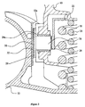
- FIG. 1 to 3 there is shown part of a bogie which is, generally of the Y25 type, the bogie comprising a pair of pedestals 10 (only part of one of which is shown) arranged parallel to one another and secured to one another, each pedestal 10 being supported by a pair of axle boxes 12.
- a pair of spring sets 14, 16 are provided between each axle box 12 and the associated pedestal.
- Each spring set 14, 16 comprises a first, outer spring 18 and an inner spring 20, the length of the inner spring 20 being chosen such that the inner spring 20 only becomes an effective part of the primary suspension once a predetermined load is carried by the bogie.
- An axle and wheel set (not shown) extends between each axle box 12 associated with one of the pedestals and a respective axle box 12 associated with the other of the pedestals 10.
- a drive member 22 in the form of a spring holder is carried by the outer spring 18 of one of the spring sets 12 and is connected to the pedestal 10 through an inclined link member known as a Lenoir link 24, as shown in Figure 2.
- the inclination of the Lenoir link 24 is arranged such that a lateral load is applied to the drive member 22, the magnitude of which is dependent upon the load carried by the bogie.
- the drive member 22 abuts a piston 26 which is guided for sliding movement relative to a part of the pedestal 10.
- a metallic sleeve 28 is provided in the pedestal 10 within which the piston 26 slides.
- the end of the piston remote from the drive member is arranged to bear against a surface 12a of the axle box, the engagement between the piston and the axle box being a metal-to-metal engagement which is undesirable.
- the piston 26 includes a composite material component 29 located such that the surface of the piston 26 which engages the axle box is not metallic but rather is of the composite material.
- the composite material component 29 comprises a plate 30 mounted upon the piston 26 and having mechanically secured or hot bonded thereto an element 32 of composite material. If desired, the composite material component 29 may be removably attached to the piston, but this need not be the case.
- the piston could be entirely or largely of a non-metallic material, if desired.
- the piston could comprise a suitably reinforced composite material component.
- the track friendliness of the bogie may be enhanced by designing the bogie in such a manner as to allow the travel of the piston or pistons to be increased from the 4mm maximum travel permitted by a typical Y25 bogie to a maximum travel of at least 7mm, and preferably around 9mm.
- such an increase in the travel of the piston or pistons may be achieved by modifying the sleeve 28 in which the piston 26 is slidable to omit the lip 28a (see Figure 3) thereof.
- a minor alteration of the design of the pedestal 10 may be made to increase the maximum permitted travel of the piston.
- Figures 6 and 7 illustrate another bogie based closely upon the standard Y25 bogie but modified in order to improve its track friendliness.
- the bogie of Figures 6 and 7 differs from a typical Y25 type bogie in four main respects. Firstly, as with the arrangement of Figure 1, the pistons 26 are provided with composite material surfaces, thereby avoiding metal-to-metal contact between the pistons and the axle box. Secondly, as with the arrangement shown in Figures 4 and 5, two pistons 26 are provided, each being driven by an associated drive arrangement using an associated Lenoir link.
- a further advantage of this mounting of the pistons 26 is that the pistons 26 are permitted to move through a small distance horizontally (generally perpendicularly to the axis of the piston), vertically, and to tilt slightly, relative to the pedestal 10, thereby providing additional degrees of freedom in the movement of the pistons 26, permitting braking inertial forces to be accommodated and axle box movement relative to the pedestal in the horizontal (fore-aft direction) and vertical direction to be accommodated. As a result, constant load dependent friction damping and axle steering can be achieved.
- the fourth important distinction between the arrangement of Figures 5 and 6 and the typical Y25 bogie resides in the spring sets 14, 16.
- the spring sets 14, 16 used in the arrangement of Figures 6 and 7 are significantly longer and softer than the spring sets typically used in a Y25 bogie.
- the arrangements illustrated in Figures 1 to 5 use the typical spring sets, and the increase in length is apparent by comparing, say, Figure 1 with Figure 6.
- a typical spring set used in a Y25 type bogie at tare weight has a length of approximately 240mm and a rate of about 980N/mm.
- the arrangement of Figures 6 and 7 has a length of about 300mm and a rate of about 390N/mm.
- axle box 12 In order to accommodate the revised spring sets into the bogie whilst still meeting the usual design criteria of a Y25 bogie, the axle box 12 has been modified as shown in Figure 6 to lower the height of the lower end of each spring set above the ground/rails, in use.
- the change in the design of the axle box 12 is such as to position the lower end of the spring sets at a height of approximately 220mm from the rails.
- any combination of the various modifications to the conventional Y25 bogie described herein may be used to provide a bogie of improved track friendliness.
Landscapes
- Engineering & Computer Science (AREA)
- Mechanical Engineering (AREA)
- Train Traffic Observation, Control, And Security (AREA)
- Handcart (AREA)
- Toys (AREA)
- Vibration Dampers (AREA)
- Springs (AREA)
- Transition And Organic Metals Composition Catalysts For Addition Polymerization (AREA)
- Vibration Prevention Devices (AREA)
- Buildings Adapted To Withstand Abnormal External Influences (AREA)
- Fluid-Damping Devices (AREA)
- Bearings For Parts Moving Linearly (AREA)
Priority Applications (4)
| Application Number | Priority Date | Filing Date | Title |
|---|---|---|---|
| PL04252767T PL1484228T3 (pl) | 2003-05-20 | 2004-05-13 | Układy tłumiące dla wózków zwrotnych Y25 |
| PL07023449T PL1925526T3 (pl) | 2003-05-20 | 2004-05-13 | Ulepszenia wózka Y25 |
| EP09154518A EP2065285A1 (de) | 2003-05-20 | 2004-05-13 | Verbesserungen bei der Spurfreundlichkeit des Y25-Drehgestells |
| EP07023449A EP1925526B1 (de) | 2003-05-20 | 2004-05-13 | Verbesserungen bei der Spurfreundlichkeit des Y25-Drehgestells |
Applications Claiming Priority (2)
| Application Number | Priority Date | Filing Date | Title |
|---|---|---|---|
| GB0311480 | 2003-05-20 | ||
| GBGB0311480.8A GB0311480D0 (en) | 2003-05-20 | 2003-05-20 | Improvements in the track friendliness of Y25 bogie |
Related Child Applications (2)
| Application Number | Title | Priority Date | Filing Date |
|---|---|---|---|
| EP07023449A Division EP1925526B1 (de) | 2003-05-20 | 2004-05-13 | Verbesserungen bei der Spurfreundlichkeit des Y25-Drehgestells |
| EP09154518A Division EP2065285A1 (de) | 2003-05-20 | 2004-05-13 | Verbesserungen bei der Spurfreundlichkeit des Y25-Drehgestells |
Publications (3)
| Publication Number | Publication Date |
|---|---|
| EP1484228A1 true EP1484228A1 (de) | 2004-12-08 |
| EP1484228B1 EP1484228B1 (de) | 2009-04-22 |
| EP1484228B8 EP1484228B8 (de) | 2009-08-05 |
Family
ID=9958356
Family Applications (3)
| Application Number | Title | Priority Date | Filing Date |
|---|---|---|---|
| EP07023449A Expired - Lifetime EP1925526B1 (de) | 2003-05-20 | 2004-05-13 | Verbesserungen bei der Spurfreundlichkeit des Y25-Drehgestells |
| EP09154518A Withdrawn EP2065285A1 (de) | 2003-05-20 | 2004-05-13 | Verbesserungen bei der Spurfreundlichkeit des Y25-Drehgestells |
| EP04252767A Expired - Lifetime EP1484228B8 (de) | 2003-05-20 | 2004-05-13 | Schwingungsdämpfende Einrichtungen für Y25 Drehgestelle |
Family Applications Before (2)
| Application Number | Title | Priority Date | Filing Date |
|---|---|---|---|
| EP07023449A Expired - Lifetime EP1925526B1 (de) | 2003-05-20 | 2004-05-13 | Verbesserungen bei der Spurfreundlichkeit des Y25-Drehgestells |
| EP09154518A Withdrawn EP2065285A1 (de) | 2003-05-20 | 2004-05-13 | Verbesserungen bei der Spurfreundlichkeit des Y25-Drehgestells |
Country Status (6)
| Country | Link |
|---|---|
| EP (3) | EP1925526B1 (de) |
| AT (2) | ATE553975T1 (de) |
| DE (1) | DE602004020702D1 (de) |
| EA (1) | EA007260B1 (de) |
| GB (6) | GB0311480D0 (de) |
| PL (2) | PL1484228T3 (de) |
Cited By (3)
| Publication number | Priority date | Publication date | Assignee | Title |
|---|---|---|---|---|
| EP3789262A1 (de) | 2019-09-09 | 2021-03-10 | VÚKV a.s. | Radsatzführung für schienenfahrzeug, insbesondere für einen güterwaggon |
| WO2021158135A1 (en) * | 2020-02-07 | 2021-08-12 | Wagony Swidnica Sp. Z.O.O. | Friction damper, particularly in bogie suspension system |
| WO2021158134A1 (en) * | 2020-02-07 | 2021-08-12 | Wagony Świdnica Sp. Z.O.O. | Friction damper, particularly in bogie suspension system |
Families Citing this family (1)
| Publication number | Priority date | Publication date | Assignee | Title |
|---|---|---|---|---|
| WO2011082823A1 (en) | 2010-01-07 | 2011-07-14 | Aktiebolaget Skf | Bogie axle box with damping interfaces |
Citations (5)
| Publication number | Priority date | Publication date | Assignee | Title |
|---|---|---|---|---|
| US3882794A (en) * | 1972-02-10 | 1975-05-13 | Talbot Waggonfab | Snubbed axle railway bogie |
| US3926127A (en) * | 1973-12-18 | 1975-12-16 | Sumitomo Metal Ind | Railway axle friction snubber assembly |
| EP1186505A2 (de) * | 2000-09-11 | 2002-03-13 | Naco Incorporated | Verschleissplatte mit zwei Reibbeiwerten für den Achslagerträger eines Drehgestell-Längsträgers eines Schienenfahrzeuges |
| EP1186504A2 (de) * | 2000-09-11 | 2002-03-13 | Naco Incorporated | Drehgestell für ein Schienenfahrzeug |
| FR2815594A1 (fr) * | 2000-10-20 | 2002-04-26 | Arbel Fauvet Rail Sa | Suspension ferroviaire equipee d'une boite d'essieu a palettes |
Family Cites Families (10)
| Publication number | Priority date | Publication date | Assignee | Title |
|---|---|---|---|---|
| BE636150A (de) * | 1960-02-03 | |||
| FR1362645A (fr) * | 1963-04-25 | 1964-06-05 | Frangeco | Dispositif d'amortissement de suspension pour véhicules |
| DE2110072C3 (de) * | 1971-03-03 | 1981-07-30 | Wegmann & Co, 3500 Kassel | Achsführung an einem Drehgestell für Schienenfahrzeuge, insbesondere für Güterwagen |
| BE790623A (fr) * | 1971-12-04 | 1973-02-15 | Linke Hofmann Busch | Boggie pour des vehicules ferroviaires |
| FR2477090A1 (fr) * | 1980-02-29 | 1981-09-04 | Sambre & Meuse Usines | Suspension pour chassis a au moins deux essieux de vehicule de chemin de fer et chassis muni de cette suspension |
| FR2490172A1 (fr) * | 1980-09-17 | 1982-03-19 | Sncf | Agencement de suspension pour vehicules ferroviaires |
| US4765251A (en) * | 1984-07-23 | 1988-08-23 | Kaser Associates, Inc. | Railway car truck with multiple effective spring rates |
| FR2648417B1 (fr) * | 1989-06-19 | 1991-09-20 | Arbel Fauvet Rail Sa | Dispositif de suspension et d'amortissement pour vehicules ferroviaires a essieux orientables |
| FR2658471B1 (fr) * | 1990-02-21 | 1992-06-12 | Sambre & Meuse Usines | Bogie a pesee de charge pour vehicules de chemin de fer. |
| US5806435A (en) * | 1996-09-06 | 1998-09-15 | Amsted Industries Incorporated | Side bearings for truck bolsters |
-
2003
- 2003-05-20 GB GBGB0311480.8A patent/GB0311480D0/en not_active Ceased
-
2004
- 2004-05-13 EP EP07023449A patent/EP1925526B1/de not_active Expired - Lifetime
- 2004-05-13 DE DE602004020702T patent/DE602004020702D1/de not_active Expired - Lifetime
- 2004-05-13 AT AT07023449T patent/ATE553975T1/de active
- 2004-05-13 EP EP09154518A patent/EP2065285A1/de not_active Withdrawn
- 2004-05-13 PL PL04252767T patent/PL1484228T3/pl unknown
- 2004-05-13 PL PL07023449T patent/PL1925526T3/pl unknown
- 2004-05-13 AT AT04252767T patent/ATE429367T1/de not_active IP Right Cessation
- 2004-05-13 EP EP04252767A patent/EP1484228B8/de not_active Expired - Lifetime
- 2004-05-17 GB GB0608209A patent/GB2422589B/en not_active Expired - Lifetime
- 2004-05-17 GB GB0608204A patent/GB2422587A/en not_active Withdrawn
- 2004-05-17 GB GB0608205A patent/GB2422814B/en not_active Expired - Lifetime
- 2004-05-17 GB GB0608207A patent/GB2422588A/en not_active Withdrawn
- 2004-05-17 GB GB0410857A patent/GB2401844B/en not_active Expired - Lifetime
- 2004-05-19 EA EA200400559A patent/EA007260B1/ru not_active IP Right Cessation
Patent Citations (5)
| Publication number | Priority date | Publication date | Assignee | Title |
|---|---|---|---|---|
| US3882794A (en) * | 1972-02-10 | 1975-05-13 | Talbot Waggonfab | Snubbed axle railway bogie |
| US3926127A (en) * | 1973-12-18 | 1975-12-16 | Sumitomo Metal Ind | Railway axle friction snubber assembly |
| EP1186505A2 (de) * | 2000-09-11 | 2002-03-13 | Naco Incorporated | Verschleissplatte mit zwei Reibbeiwerten für den Achslagerträger eines Drehgestell-Längsträgers eines Schienenfahrzeuges |
| EP1186504A2 (de) * | 2000-09-11 | 2002-03-13 | Naco Incorporated | Drehgestell für ein Schienenfahrzeug |
| FR2815594A1 (fr) * | 2000-10-20 | 2002-04-26 | Arbel Fauvet Rail Sa | Suspension ferroviaire equipee d'une boite d'essieu a palettes |
Cited By (3)
| Publication number | Priority date | Publication date | Assignee | Title |
|---|---|---|---|---|
| EP3789262A1 (de) | 2019-09-09 | 2021-03-10 | VÚKV a.s. | Radsatzführung für schienenfahrzeug, insbesondere für einen güterwaggon |
| WO2021158135A1 (en) * | 2020-02-07 | 2021-08-12 | Wagony Swidnica Sp. Z.O.O. | Friction damper, particularly in bogie suspension system |
| WO2021158134A1 (en) * | 2020-02-07 | 2021-08-12 | Wagony Świdnica Sp. Z.O.O. | Friction damper, particularly in bogie suspension system |
Also Published As
| Publication number | Publication date |
|---|---|
| GB2401844B (en) | 2006-07-26 |
| GB2422588A (en) | 2006-08-02 |
| GB0608207D0 (en) | 2006-06-07 |
| PL1925526T3 (pl) | 2012-10-31 |
| EA200400559A1 (ru) | 2004-12-30 |
| GB2401844A (en) | 2004-11-24 |
| EP1484228B1 (de) | 2009-04-22 |
| GB2422814B (en) | 2007-11-21 |
| EP1484228B8 (de) | 2009-08-05 |
| EP1925526A1 (de) | 2008-05-28 |
| GB0608205D0 (en) | 2006-06-07 |
| GB0311480D0 (en) | 2003-06-25 |
| GB0608209D0 (en) | 2006-06-07 |
| GB2422589B (en) | 2006-12-06 |
| GB2422814A (en) | 2006-08-09 |
| DE602004020702D1 (de) | 2009-06-04 |
| PL1484228T3 (pl) | 2009-10-30 |
| GB0410857D0 (en) | 2004-06-16 |
| EP2065285A1 (de) | 2009-06-03 |
| EP1925526B1 (de) | 2012-04-18 |
| GB2422587A (en) | 2006-08-02 |
| GB0608204D0 (en) | 2006-06-07 |
| ATE553975T1 (de) | 2012-05-15 |
| ATE429367T1 (de) | 2009-05-15 |
| EA007260B1 (ru) | 2006-08-25 |
| GB2422589A (en) | 2006-08-02 |
Similar Documents
| Publication | Publication Date | Title |
|---|---|---|
| AU2004202601B2 (en) | Three-piece Motion Control Truck System | |
| CA2648376C (en) | Railroad freight car sidebearing | |
| RU2370388C2 (ru) | Опорный скользун тележки железнодорожного вагона (варианты) | |
| US8104409B2 (en) | Rail car suspension damping | |
| US20180257677A1 (en) | Railway car truck friction shoe spring group | |
| RU2602912C1 (ru) | Тележка железнодорожного товарного вагона с фрикционным демпфированием | |
| US5331902A (en) | Truck boltser with laterally wider friction show pocket and mechanism for lateral travel of the friction shoe | |
| US8689701B2 (en) | Railroad car wheel truck | |
| EP2797800B1 (de) | Zweiteiliges drehgestell mit einem neuen aufhängungssystem | |
| US20200269887A1 (en) | Railroad Truck Providing Improved Dynamic Characteristics Of The Freight Railway Car And The Railroad Truck Components | |
| EP1484228B1 (de) | Schwingungsdämpfende Einrichtungen für Y25 Drehgestelle | |
| RU2670550C1 (ru) | Фрикционный клин тележки железнодорожного вагона | |
| AU2009210376B2 (en) | Rail car suspension damping | |
| RU2674220C1 (ru) | Фрикционный клин тележки железнодорожного вагона | |
| US6092469A (en) | Radially side mounted railway car truck | |
| WO2017104464A1 (ja) | 鉄道車両用操舵台車 | |
| RU2292281C1 (ru) | Фрикционный гаситель колебаний тележки железнодорожного вагона | |
| RU2248286C2 (ru) | Ходовая тележка грузового железнодорожного вагона | |
| US20180257675A1 (en) | Railway car truck friction shoe | |
| EP1479585A1 (de) | Einbau der Achsbuchsen in einem Drehgestell | |
| US1916149A (en) | Truck | |
| RU54866U1 (ru) | Подвеска транспортного средства |
Legal Events
| Date | Code | Title | Description |
|---|---|---|---|
| PUAI | Public reference made under article 153(3) epc to a published international application that has entered the european phase |
Free format text: ORIGINAL CODE: 0009012 |
|
| AK | Designated contracting states |
Kind code of ref document: A1 Designated state(s): AT BE BG CH CY CZ DE DK EE ES FI FR GB GR HU IE IT LI LU MC NL PL PT RO SE SI SK TR |
|
| AX | Request for extension of the european patent |
Extension state: AL HR LT LV MK |
|
| RAP1 | Party data changed (applicant data changed or rights of an application transferred) |
Owner name: ENGLISH WELSH & SCOTTISH RAILWAY HOLDINGS LIMI |
|
| AKX | Designation fees paid |
Designated state(s): AT BE BG CH CY CZ DE DK EE ES FI FR GB GR HU IE IT LI LU MC NL PL PT RO SE SI SK TR |
|
| 17P | Request for examination filed |
Effective date: 20050629 |
|
| RBV | Designated contracting states (corrected) |
Designated state(s): AT BE BG CH CY CZ DE DK EE ES FI FR GB GR HU IE IT LI LU MC NL PL PT RO SE SI SK TR |
|
| 17Q | First examination report despatched |
Effective date: 20070817 |
|
| GRAP | Despatch of communication of intention to grant a patent |
Free format text: ORIGINAL CODE: EPIDOSNIGR1 |
|
| GRAS | Grant fee paid |
Free format text: ORIGINAL CODE: EPIDOSNIGR3 |
|
| GRAA | (expected) grant |
Free format text: ORIGINAL CODE: 0009210 |
|
| RBV | Designated contracting states (corrected) |
Designated state(s): AT BE BG CH CY CZ DE DK EE ES FI FR GR HU IE IT LI LU MC NL PL PT RO SE SI SK TR |
|
| RIN1 | Information on inventor provided before grant (corrected) |
Inventor name: HEWITT, PAUL,RUA PRINCIPAL 56 |
|
| AK | Designated contracting states |
Kind code of ref document: B1 Designated state(s): AT BE BG CH CY CZ DE DK EE ES FI FR GR HU IE IT LI LU MC NL PL PT RO SE SI SK TR |
|
| REG | Reference to a national code |
Ref country code: CH Ref legal event code: EP |
|
| REG | Reference to a national code |
Ref country code: IE Ref legal event code: FG4D |
|
| RAP2 | Party data changed (patent owner data changed or rights of a patent transferred) |
Owner name: ENGLISH WELSH & SCOTTISH RAILWAY HOLDINGS LIMITED |
|
| REF | Corresponds to: |
Ref document number: 602004020702 Country of ref document: DE Date of ref document: 20090604 Kind code of ref document: P |
|
| NLT2 | Nl: modifications (of names), taken from the european patent patent bulletin |
Owner name: ENGLISH WELSH & SCOTTISH RAILWAY HOLDINGS LIMITED Effective date: 20090527 |
|
| NLV1 | Nl: lapsed or annulled due to failure to fulfill the requirements of art. 29p and 29m of the patents act | ||
| PG25 | Lapsed in a contracting state [announced via postgrant information from national office to epo] |
Ref country code: PT Free format text: LAPSE BECAUSE OF FAILURE TO SUBMIT A TRANSLATION OF THE DESCRIPTION OR TO PAY THE FEE WITHIN THE PRESCRIBED TIME-LIMIT Effective date: 20090822 Ref country code: ES Free format text: LAPSE BECAUSE OF FAILURE TO SUBMIT A TRANSLATION OF THE DESCRIPTION OR TO PAY THE FEE WITHIN THE PRESCRIBED TIME-LIMIT Effective date: 20090802 Ref country code: AT Free format text: LAPSE BECAUSE OF FAILURE TO SUBMIT A TRANSLATION OF THE DESCRIPTION OR TO PAY THE FEE WITHIN THE PRESCRIBED TIME-LIMIT Effective date: 20090422 |
|
| REG | Reference to a national code |
Ref country code: PL Ref legal event code: T3 |
|
| PG25 | Lapsed in a contracting state [announced via postgrant information from national office to epo] |
Ref country code: SI Free format text: LAPSE BECAUSE OF FAILURE TO SUBMIT A TRANSLATION OF THE DESCRIPTION OR TO PAY THE FEE WITHIN THE PRESCRIBED TIME-LIMIT Effective date: 20090422 Ref country code: SE Free format text: LAPSE BECAUSE OF FAILURE TO SUBMIT A TRANSLATION OF THE DESCRIPTION OR TO PAY THE FEE WITHIN THE PRESCRIBED TIME-LIMIT Effective date: 20090722 Ref country code: NL Free format text: LAPSE BECAUSE OF FAILURE TO SUBMIT A TRANSLATION OF THE DESCRIPTION OR TO PAY THE FEE WITHIN THE PRESCRIBED TIME-LIMIT Effective date: 20090422 |
|
| PG25 | Lapsed in a contracting state [announced via postgrant information from national office to epo] |
Ref country code: MC Free format text: LAPSE BECAUSE OF NON-PAYMENT OF DUE FEES Effective date: 20090531 |
|
| REG | Reference to a national code |
Ref country code: CH Ref legal event code: PL |
|
| PG25 | Lapsed in a contracting state [announced via postgrant information from national office to epo] |
Ref country code: RO Free format text: LAPSE BECAUSE OF FAILURE TO SUBMIT A TRANSLATION OF THE DESCRIPTION OR TO PAY THE FEE WITHIN THE PRESCRIBED TIME-LIMIT Effective date: 20090422 Ref country code: EE Free format text: LAPSE BECAUSE OF FAILURE TO SUBMIT A TRANSLATION OF THE DESCRIPTION OR TO PAY THE FEE WITHIN THE PRESCRIBED TIME-LIMIT Effective date: 20090422 Ref country code: CH Free format text: LAPSE BECAUSE OF NON-PAYMENT OF DUE FEES Effective date: 20090531 Ref country code: DK Free format text: LAPSE BECAUSE OF FAILURE TO SUBMIT A TRANSLATION OF THE DESCRIPTION OR TO PAY THE FEE WITHIN THE PRESCRIBED TIME-LIMIT Effective date: 20090422 Ref country code: CZ Free format text: LAPSE BECAUSE OF FAILURE TO SUBMIT A TRANSLATION OF THE DESCRIPTION OR TO PAY THE FEE WITHIN THE PRESCRIBED TIME-LIMIT Effective date: 20090422 Ref country code: LI Free format text: LAPSE BECAUSE OF NON-PAYMENT OF DUE FEES Effective date: 20090531 |
|
| PG25 | Lapsed in a contracting state [announced via postgrant information from national office to epo] |
Ref country code: SK Free format text: LAPSE BECAUSE OF FAILURE TO SUBMIT A TRANSLATION OF THE DESCRIPTION OR TO PAY THE FEE WITHIN THE PRESCRIBED TIME-LIMIT Effective date: 20090422 Ref country code: BE Free format text: LAPSE BECAUSE OF FAILURE TO SUBMIT A TRANSLATION OF THE DESCRIPTION OR TO PAY THE FEE WITHIN THE PRESCRIBED TIME-LIMIT Effective date: 20090422 |
|
| PLBE | No opposition filed within time limit |
Free format text: ORIGINAL CODE: 0009261 |
|
| STAA | Information on the status of an ep patent application or granted ep patent |
Free format text: STATUS: NO OPPOSITION FILED WITHIN TIME LIMIT |
|
| 26N | No opposition filed |
Effective date: 20100125 |
|
| PG25 | Lapsed in a contracting state [announced via postgrant information from national office to epo] |
Ref country code: BG Free format text: LAPSE BECAUSE OF FAILURE TO SUBMIT A TRANSLATION OF THE DESCRIPTION OR TO PAY THE FEE WITHIN THE PRESCRIBED TIME-LIMIT Effective date: 20090722 |
|
| PG25 | Lapsed in a contracting state [announced via postgrant information from national office to epo] |
Ref country code: IE Free format text: LAPSE BECAUSE OF NON-PAYMENT OF DUE FEES Effective date: 20090513 |
|
| PG25 | Lapsed in a contracting state [announced via postgrant information from national office to epo] |
Ref country code: GR Free format text: LAPSE BECAUSE OF FAILURE TO SUBMIT A TRANSLATION OF THE DESCRIPTION OR TO PAY THE FEE WITHIN THE PRESCRIBED TIME-LIMIT Effective date: 20090723 |
|
| PG25 | Lapsed in a contracting state [announced via postgrant information from national office to epo] |
Ref country code: IT Free format text: LAPSE BECAUSE OF FAILURE TO SUBMIT A TRANSLATION OF THE DESCRIPTION OR TO PAY THE FEE WITHIN THE PRESCRIBED TIME-LIMIT Effective date: 20090422 |
|
| PG25 | Lapsed in a contracting state [announced via postgrant information from national office to epo] |
Ref country code: LU Free format text: LAPSE BECAUSE OF NON-PAYMENT OF DUE FEES Effective date: 20090513 |
|
| PG25 | Lapsed in a contracting state [announced via postgrant information from national office to epo] |
Ref country code: HU Free format text: LAPSE BECAUSE OF FAILURE TO SUBMIT A TRANSLATION OF THE DESCRIPTION OR TO PAY THE FEE WITHIN THE PRESCRIBED TIME-LIMIT Effective date: 20091023 |
|
| PG25 | Lapsed in a contracting state [announced via postgrant information from national office to epo] |
Ref country code: TR Free format text: LAPSE BECAUSE OF FAILURE TO SUBMIT A TRANSLATION OF THE DESCRIPTION OR TO PAY THE FEE WITHIN THE PRESCRIBED TIME-LIMIT Effective date: 20090422 |
|
| PG25 | Lapsed in a contracting state [announced via postgrant information from national office to epo] |
Ref country code: CY Free format text: LAPSE BECAUSE OF FAILURE TO SUBMIT A TRANSLATION OF THE DESCRIPTION OR TO PAY THE FEE WITHIN THE PRESCRIBED TIME-LIMIT Effective date: 20090422 |
|
| REG | Reference to a national code |
Ref country code: DE Ref legal event code: R081 Ref document number: 602004020702 Country of ref document: DE Owner name: DB SCHENKER RAIL (UK) HOLDINGS LTD., GB Free format text: FORMER OWNER: ENGLISH WELSH & SCOTTISH RAILWAY HOLDINGS LTD., DONCASTER, GB Effective date: 20130726 Ref country code: DE Ref legal event code: R081 Ref document number: 602004020702 Country of ref document: DE Owner name: DB SCHENKER RAIL (UK) HOLDINGS LTD., DONCASTER, GB Free format text: FORMER OWNER: ENGLISH WELSH & SCOTTISH RAILWAY HOLDINGS LTD., DONCASTER, SOUTH YORKSHIRE, GB Effective date: 20130726 Ref country code: DE Ref legal event code: R081 Ref document number: 602004020702 Country of ref document: DE Owner name: DB CARGO (UK) HOLDINGS LIMITED, DONCASTER, GB Free format text: FORMER OWNER: ENGLISH WELSH & SCOTTISH RAILWAY HOLDINGS LTD., DONCASTER, SOUTH YORKSHIRE, GB Effective date: 20130726 Ref country code: DE Ref legal event code: R081 Ref document number: 602004020702 Country of ref document: DE Owner name: WABTEC RAIL LTD., GB Free format text: FORMER OWNER: ENGLISH WELSH & SCOTTISH RAILWAY HOLDINGS LTD., DONCASTER, SOUTH YORKSHIRE, GB Effective date: 20130726 |
|
| REG | Reference to a national code |
Ref country code: FR Ref legal event code: PLFP Year of fee payment: 13 |
|
| REG | Reference to a national code |
Ref country code: DE Ref legal event code: R081 Ref document number: 602004020702 Country of ref document: DE Owner name: DB CARGO (UK) HOLDINGS LIMITED, DONCASTER, GB Free format text: FORMER OWNER: DB SCHENKER RAIL (UK) HOLDINGS LTD., DONCASTER, SOUTH YORKSHIRE, GB Ref country code: DE Ref legal event code: R081 Ref document number: 602004020702 Country of ref document: DE Owner name: WABTEC RAIL LTD., GB Free format text: FORMER OWNER: DB SCHENKER RAIL (UK) HOLDINGS LTD., DONCASTER, SOUTH YORKSHIRE, GB |
|
| REG | Reference to a national code |
Ref country code: FR Ref legal event code: CD Owner name: DB CARGO (UK) LIMITED, GB Effective date: 20161114 |
|
| REG | Reference to a national code |
Ref country code: FR Ref legal event code: PLFP Year of fee payment: 14 |
|
| REG | Reference to a national code |
Ref country code: DE Ref legal event code: R081 Ref document number: 602004020702 Country of ref document: DE Owner name: WABTEC RAIL LTD., GB Free format text: FORMER OWNER: DB CARGO (UK) HOLDINGS LIMITED, DONCASTER, SOUTH YORKSHIRE, GB |
|
| REG | Reference to a national code |
Ref country code: FR Ref legal event code: PLFP Year of fee payment: 15 |
|
| REG | Reference to a national code |
Ref country code: FR Ref legal event code: RM Effective date: 20180917 Ref country code: FR Ref legal event code: TP Owner name: WABTEC RAIL LIMITED, GB Effective date: 20180917 |
|
| REG | Reference to a national code |
Ref country code: DE Ref legal event code: R082 Ref document number: 602004020702 Country of ref document: DE Representative=s name: WITHERS & ROGERS LLP, DE |
|
| P01 | Opt-out of the competence of the unified patent court (upc) registered |
Effective date: 20230530 |
|
| PGFP | Annual fee paid to national office [announced via postgrant information from national office to epo] |
Ref country code: FR Payment date: 20230530 Year of fee payment: 20 Ref country code: DE Payment date: 20230517 Year of fee payment: 20 |
|
| PGFP | Annual fee paid to national office [announced via postgrant information from national office to epo] |
Ref country code: PL Payment date: 20230504 Year of fee payment: 20 Ref country code: FI Payment date: 20230526 Year of fee payment: 20 |
|
| REG | Reference to a national code |
Ref country code: DE Ref legal event code: R071 Ref document number: 602004020702 Country of ref document: DE |