EP1484449A2 - Dispositif de séparation et de transport des matériaux séparables - Google Patents
Dispositif de séparation et de transport des matériaux séparables Download PDFInfo
- Publication number
- EP1484449A2 EP1484449A2 EP04008815A EP04008815A EP1484449A2 EP 1484449 A2 EP1484449 A2 EP 1484449A2 EP 04008815 A EP04008815 A EP 04008815A EP 04008815 A EP04008815 A EP 04008815A EP 1484449 A2 EP1484449 A2 EP 1484449A2
- Authority
- EP
- European Patent Office
- Prior art keywords
- sieve
- elements
- chains
- chain
- brush
- Prior art date
- Legal status (The legal status is an assumption and is not a legal conclusion. Google has not performed a legal analysis and makes no representation as to the accuracy of the status listed.)
- Withdrawn
Links
Images
Classifications
-
- E—FIXED CONSTRUCTIONS
- E02—HYDRAULIC ENGINEERING; FOUNDATIONS; SOIL SHIFTING
- E02B—HYDRAULIC ENGINEERING
- E02B8/00—Details of barrages or weirs ; Energy dissipating devices carried by lock or dry-dock gates
- E02B8/02—Sediment base gates; Sand sluices; Structures for retaining arresting waterborne material
- E02B8/023—Arresting devices for waterborne materials
- E02B8/026—Cleaning devices
-
- B—PERFORMING OPERATIONS; TRANSPORTING
- B01—PHYSICAL OR CHEMICAL PROCESSES OR APPARATUS IN GENERAL
- B01D—SEPARATION
- B01D33/00—Filters with filtering elements which move during the filtering operation
- B01D33/27—Filters with filtering elements which move during the filtering operation with rotary filtering surfaces, which are neither cylindrical nor planar, e.g. helical surfaces
- B01D33/275—Filters with filtering elements which move during the filtering operation with rotary filtering surfaces, which are neither cylindrical nor planar, e.g. helical surfaces using contiguous impervious surfaces
-
- B—PERFORMING OPERATIONS; TRANSPORTING
- B01—PHYSICAL OR CHEMICAL PROCESSES OR APPARATUS IN GENERAL
- B01D—SEPARATION
- B01D33/00—Filters with filtering elements which move during the filtering operation
- B01D33/44—Regenerating the filter material in the filter
- B01D33/46—Regenerating the filter material in the filter by scrapers, brushes nozzles or the like acting on the cake-side of the filtering element
- B01D33/465—Regenerating the filter material in the filter by scrapers, brushes nozzles or the like acting on the cake-side of the filtering element take-off rollers
-
- B—PERFORMING OPERATIONS; TRANSPORTING
- B01—PHYSICAL OR CHEMICAL PROCESSES OR APPARATUS IN GENERAL
- B01D—SEPARATION
- B01D33/00—Filters with filtering elements which move during the filtering operation
- B01D33/80—Accessories
- B01D33/801—Driving means, shaft packing systems or the like
Definitions
- the present invention relates to a device for separation and removal separating material from a flowing liquid, for example Wastewater, with two endless circulating ones immersed in the liquid Chains, each of which have chain links, which are connected to one another by means of joints are connected and with sieve elements arranged between the chains, each fixed to a chain link of each chain are.
- a conveyor belt filter device also called circulation rake, for mechanical Cleaning of a flowing in a channel, contaminated with solids Liquid is known for example from EP 0 676 227 B1.
- circulation rake for mechanical Cleaning of a flowing in a channel, contaminated with solids Liquid
- Such Devices are used primarily for mechanical cleaning Sewage, with the lower part of the device flowing into the Liquid is immersed.
- the sieve elements attached to the device are flowed through by the wastewater, with what is to be separated Well collects on the sieve elements and there from the liquid upwards is transported away.
- Coarse solids as well as fine-grained filter material To be able to convey out of the liquid was accordingly proposed the filter elements with a constant small distance from each other to arrange.
- the filter elements designed in this way have continue to areas that move towards each other in the area of the deflection and thus to squeeze contaminants inside being able to lead. These areas have to be cleaned again in order to function properly to ensure the device.
- the individual Filter elements can be positioned very exactly in relation to each other to be the same Maintain gap widths and thus filter out the material to be separated to be able to perform defined between the filter elements.
- the object of the present invention is therefore a device for separating and removal of material to be separated from a flowing liquid to create, which has a uniform cleaning effect and is also largely low-maintenance.
- the object is achieved with devices with the features of the independent Expectations.
- each of the chains has chain links that are connected by means of joints are interconnected.
- Sieve elements arranged between the chains are fixed to a chain link of each chain attached. This prevents the screen elements from undefined movements can carry out and separating the position of the sieve elements could affect.
- the sieve elements are therefore firm and immobile with the chain links connected.
- the filtering of the material to be separated remains constant on the sieve elements
- adjacent Sieve elements in the direction of the chain in the area of the joints of the Chain links overlap.
- the Overlapping the sieve elements creates a kind of labyrinth seal, whereby it complicates the liquid and therefore especially the material to be separated is prevented in the area between two screen elements Penetrate device.
- Most of the liquid must be forced through this flow through the sieve elements themselves and thereby cause uniform filtering of the material to be separated from the liquid accordingly the openings provided in the sieve element.
- the device according to the invention is particularly low-maintenance and reliable in its mode of action.
- the brush As a cleaning device for the device, it is advantageous if in the area the deflection of the chain arranged a rotating brush in particular is.
- the brush also cleans itself the open cavity or, depending on the version, essentially continuously continuous surface of the sieve elements also in the area the overlapping ends of the screen elements.
- the screen element is essentially outside the Level of the chains lies. This will open the overlap of two adjacent sieve elements in the area of the deflection of the chain without further structural measures.
- a sieve element according to the invention can be produced particularly easily, if the sieve element has perforated sieve surfaces.
- the perforation can selected according to the contaminants to be separated from the liquid become.
- certain areas can have a hole pattern, while other areas of the screen element remain unperforated.
- the sieve element is curved in the direction facing away from the chain is. This has a particularly advantageous effect that the material to be separated on adheres well to the sieve element and is transported upwards out of the liquid can be.
- the sieve element To attach the sieve element particularly easily to the chain links the sieve element at the ends, which faces the chains are completed with a lid.
- the lid By means of the lid that is Siebel element finally attached to the chain links, especially screwed.
- the sieve element is thus fixed, i.e. immobile with each a chain link connected at one end of the screen element and thus integral part of the two chains of the device.
- the two chains are firmly and parallel connected, so that a rigid unit is created, which only on the joints the chain links, which are also axially assigned to each other, can be bent and can thus be deflected on deflection wheels.
- At least one, preferably several reinforcing plates arranged on the side which is the Chains facing.
- the reinforcement plates can be used simultaneously as part of the cavity that is created when the screen elements overlap, or serve as their wall.
- the reinforcement plates effect it addition that the sieve elements also the flow pressure of the liquid Can withstand without bending, for example, and thereby would open an undefined gap between the sieve elements.
- the cleaning effect of the brush is particularly intense when it is like this is arranged that they with their brush tips on the chain links and with its sides on the housing wall and / or the ends of the sieve element, in particular on its lids. This will make the gap almost completely between the sieve elements, the chain and the housing wall filled with the brushes and also has frictional contact, so that a good sealing effect against the material to be separated is achieved.
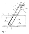
- Figure 1 shows a cross section through the side view of a separator 1, which is often referred to as circulation rake.
- the separator 1 is partially in a liquid flowing in the direction of the arrow 2 immersed in a channel 3.
- the liquid 2 points in front of the separator 1 a higher level than behind the separator 1, because the water 2 builds up in front of the separator 1 and passes through the separating device 1 with a delay.
- the separator 1 is attached to the channel 3 with a holder 4.
- To avoid of deposits is the separating device 1 on a bottom jump 5 arranged. This results in better hydraulics.
- the separating device 1 essentially consists of a conveyor belt, which is deflected on two pulleys 6.
- the endless conveyor belt consists of two chains 7 running parallel to each other, of which in the representation of Figure 1 only a chain is visible and a variety sieve elements 8 arranged thereon.
- In the area of the lower deflection roller 6 is on the side facing the flow in the area of everyone Chain 7 each have a brush 9 arranged.
- the brush 9 causes the one hand Cleaning the chain 7 and on the other hand the seal to the liquid 2 'because the brushes 9 prevent the side of the separator 1 between the separating device 1 and the channel 3 material to be separated can flow past.
- a further brush 10 is arranged in the area of the upper deflection roller 6, which is driven.
- the brush 10 causes a stripping of the Siebelementen 8 adhering material to be separated and at the same time cleaning the sieve elements 8.
- a rake 13 is arranged.
- the material to be separated is held by the rake 13 and also moves over the upper pulley 6 and then falls through the shaft 12 into the device provided for removal.
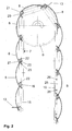
- FIG. 2 shows a detail in the area of the upper deflection roller 6 of the separating device 1.
- Joint axes 16 engage in depressions of the deflection roller 6 a, with which chain links 15 of the chain 7 articulated together are.
- the chain links 15 each have a length which is essentially corresponds to the length of a sieve element 8.
- the overlap is caused by a bevel End 20 of the first screen element 8 and the other end 21 of the following sieve element 8.
- the surface of the sieve elements 8 is curved, so that the inclusion of Separated material is improved. Serves to stabilize the screen element 8 on the one hand the folded end 20 and on the other hand next to the curvature the sieve element 8 also reinforcing plates 22 and 23, which of the Collection surface of the screen element 8 arranged in the direction of the chain 7 are.
- the actual screen surface of the screen element 8 is located between the two reinforcement plates 22 and 23. From the area in which the reinforcing plates 22 and 23 arranged on the screen element 8 are, the sieve element 8 is unperforated, which means at the overlap points the sieve elements 8 largely flow through the liquid 2 is prevented and also the attachment of the reinforcing elements 22 is facilitated.
- the two ends 20 and 21 migrate towards one another over that the cavity between the ends 20 and 21 and the Reinforcement plate 22 is dissolved and a substantially uninterrupted, Continuous surface of the screen elements 8 forms.
- This surface can be cleaned very easily by the brush 10, so that at one re-circulating the chain the cavity between the overlapping ends the sieve elements 8 is again fully functional.
- the sieve elements are also in this position, that no separated material separated from the sieve elements 8 between the chain center and thus falls back into the already cleaned liquid.
- the ends 20 and 21 of the screen elements 8 do not touch, but are just close to each other. Due to the contactless overlap in In connection with the labyrinth seal, a penetration of material to be separated becomes effectively prevented in the gap between two screen elements 8.
- Lids 25 are shown as an example on two screen elements 8, which the sieve element 8 at its two ends facing the chains 7 to lock.
- the covers 25 are welded to the sieve element 8. With Screws 26 is the cover 25 and thus the sieve element 8 on one Chain link 15 screwed and thus forms a firm connection of the Sieve element 8 with the chain 7.
- the sieve element 8 and the chain link 15 form a unit that is immovable relative to each other.
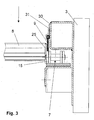
- FIG. 3 shows a section from the area of the lower deflection, in which a brush 9 is arranged.
- the brush 9 presses with the brush tips on the chain link 15, which is the lid 25 of the screen element 8 is assigned.
- the brush is 9 in the gap between the lid 25 and a housing wall 30 is arranged and thus largely seals the gap, so that impurities in the Liquid which are separated in the separating device 1 should not be able to penetrate the gap.
- the sieve element 9 is included a clamping plate 31 arranged on the side of the housing wall 30, which the end face of the screen element 8 or the cover 25 is facing. This results in a lateral stabilization of the brush elements of the brush 9 achieved, which additionally seals the screen element 8 against the housing wall 30, which is arranged on the channel 3, are effected.
- the brush 9 thus ensures the same as the overlapping area of the individual Sieve elements 8 that the area behind the sieve element 8 largely sealed against solids and thus an excellent Cleaning the liquid can be done.
- the present invention is not limited to the illustrated embodiments limited. Variations, especially in the design of the screen elements fall according to the wording of the claims also within the scope of the present invention. So in particular the overlap of the screen elements 8 not only in the manner shown and way with the same sieve elements 8, but also alternately with Larger and smaller sieve elements 8, which are also a Can form overlap. Was shown in the exemplary embodiments only the currently preferred embodiment of the invention.
Landscapes
- Chemical & Material Sciences (AREA)
- Chemical Kinetics & Catalysis (AREA)
- Engineering & Computer Science (AREA)
- General Engineering & Computer Science (AREA)
- Mechanical Engineering (AREA)
- Civil Engineering (AREA)
- Structural Engineering (AREA)
- Filtration Of Liquid (AREA)
Applications Claiming Priority (2)
| Application Number | Priority Date | Filing Date | Title |
|---|---|---|---|
| DE10325115 | 2003-06-02 | ||
| DE10325115A DE10325115A1 (de) | 2003-06-02 | 2003-06-02 | Vorrichtung zum Abscheiden und Abtransport von Abscheidegut |
Publications (2)
| Publication Number | Publication Date |
|---|---|
| EP1484449A2 true EP1484449A2 (fr) | 2004-12-08 |
| EP1484449A3 EP1484449A3 (fr) | 2005-12-28 |
Family
ID=33154534
Family Applications (1)
| Application Number | Title | Priority Date | Filing Date |
|---|---|---|---|
| EP04008815A Withdrawn EP1484449A3 (fr) | 2003-06-02 | 2004-04-14 | Dispositif de séparation et de transport des matériaux séparables |
Country Status (5)
| Country | Link |
|---|---|
| US (1) | US20050016908A1 (fr) |
| EP (1) | EP1484449A3 (fr) |
| CN (1) | CN1572978A (fr) |
| DE (1) | DE10325115A1 (fr) |
| ZA (1) | ZA200403867B (fr) |
Cited By (1)
| Publication number | Priority date | Publication date | Assignee | Title |
|---|---|---|---|---|
| GB2421200B (en) * | 2004-12-20 | 2009-10-07 | Hans Huber Ag Masch & Anlagenb | Device for removing and carrying off filtered deposits |
Families Citing this family (9)
| Publication number | Priority date | Publication date | Assignee | Title |
|---|---|---|---|---|
| KR100655469B1 (ko) * | 2006-01-16 | 2006-12-11 | 삼양정수공업 주식회사 | 유효면적을 증대시킨 회전바 스크린 필터장치 |
| DE102013111915A1 (de) * | 2013-10-29 | 2015-04-30 | Huber Se | Siebvorrichtung zum Abscheiden und Abtransport von Verunreinigungen aus Abwasser |
| SE538191C2 (sv) * | 2014-08-20 | 2016-03-29 | Mellegård & Naij Ab | Filtreringsanordning innefattande ett transportband försettmed perforerade segment |
| USD828486S1 (en) | 2015-08-06 | 2018-09-11 | Evoqua Water Technologies Llc | Fine mesh traveling water screen assembly |
| KR101648938B1 (ko) * | 2016-02-25 | 2016-08-19 | 주식회사 에싸 | 3방향 스크린 장치 |
| CN107716262A (zh) * | 2017-11-08 | 2018-02-23 | 刘全义 | 网带平回筛进行粮食除杂的方法 |
| JP2021181743A (ja) * | 2020-05-15 | 2021-11-25 | 株式会社ミゾタ | ネットシャワー洗浄装置付除塵機 |
| US11633680B2 (en) * | 2020-07-23 | 2023-04-25 | Parkson Corporation | Bar screen filter apparatus and method |
| DE102024119188B3 (de) * | 2024-07-05 | 2025-03-20 | ReTec Research and Development GmbH | Verfahren zur Behandlung von Abwasser und Abwasserbehandlungsanlage |
Citations (2)
| Publication number | Priority date | Publication date | Assignee | Title |
|---|---|---|---|---|
| DE4200366C2 (de) | 1992-01-09 | 1994-07-07 | August Frebe Gmbh | Filterrechen |
| EP0676227B1 (fr) | 1994-04-08 | 1997-12-17 | Dieter Frankenberger | Dispositif de filtration en forme d'une bande transporteuse |
Family Cites Families (19)
| Publication number | Priority date | Publication date | Assignee | Title |
|---|---|---|---|---|
| US1856381A (en) * | 1932-05-03 | Endless traveling water screen | ||
| US1564451A (en) * | 1924-12-26 | 1925-12-08 | Sargent & Lundy Inc | Traveling screen |
| US1910860A (en) * | 1930-10-31 | 1933-05-23 | Link Belt Co | Tray for water screens |
| BE385406A (fr) * | 1931-01-28 | |||
| US2286332A (en) * | 1940-02-01 | 1942-06-16 | Chain Belt Co | Chain link attachment for traveling water screens |
| US2804209A (en) * | 1953-03-06 | 1957-08-27 | Link Belt Co | Water intake screen |
| CH348126A (de) * | 1956-01-21 | 1960-07-31 | Passavant Werke | Wasserreinigungsmaschine mit endlosem, umlaufendem Siebkörper |
| GB1368464A (en) * | 1971-02-02 | 1974-09-25 | Hope W E | Apparatus for the continuous separation of fine particles from liquor |
| US3802565A (en) * | 1972-05-22 | 1974-04-09 | Fmc Corp | Water intake screen |
| US4360426A (en) * | 1981-03-02 | 1982-11-23 | Fmc Corporation | Joint between traveling water screen trays |
| DE4016450A1 (de) * | 1990-05-22 | 1991-11-28 | Steinmann & Ittig Gmbh & Co Kg | Siebbandrechen |
| DE4224641C2 (de) * | 1991-07-30 | 1999-07-29 | Schneider B V | Anlage zum Entsorgen von Abwasser, das bei der Tierhaltung anfällt, und Verfahren zum Betrieb der Anlage |
| US5326460A (en) * | 1993-02-10 | 1994-07-05 | Envirex Inc. | Pretensioned mesh insert and method for producing a pretensioned mesh insert |
| US5415766A (en) * | 1994-03-02 | 1995-05-16 | Envirex Inc. | Traveling water screen including boot seal |
| US5501793A (en) * | 1994-03-31 | 1996-03-26 | Envirex Inc. | Traveling water screen including improved basket |
| DE19654132A1 (de) * | 1996-12-23 | 1998-03-19 | Geiger Maschf Helmut | Siebrechen |
| AT405744B (de) * | 1997-11-05 | 1999-11-25 | Andritz Patentverwaltung | Siebrechen |
| DE19814140C1 (de) * | 1998-03-30 | 1999-11-11 | Noggerath Holding Gmbh Co Kg | Umlauf-Siebrechen, Tragrahmen für einen Umlauf-Siebrechen und Steuerlasche eines Siebelements |
| AT2773U1 (de) * | 1998-06-15 | 1999-04-26 | Mahr Gernot | Recheneinrichtung |
-
2003
- 2003-06-02 DE DE10325115A patent/DE10325115A1/de not_active Withdrawn
-
2004
- 2004-04-14 EP EP04008815A patent/EP1484449A3/fr not_active Withdrawn
- 2004-05-19 ZA ZA200403867A patent/ZA200403867B/xx unknown
- 2004-05-31 CN CNA200410046004XA patent/CN1572978A/zh active Pending
- 2004-06-01 US US10/858,568 patent/US20050016908A1/en not_active Abandoned
Patent Citations (2)
| Publication number | Priority date | Publication date | Assignee | Title |
|---|---|---|---|---|
| DE4200366C2 (de) | 1992-01-09 | 1994-07-07 | August Frebe Gmbh | Filterrechen |
| EP0676227B1 (fr) | 1994-04-08 | 1997-12-17 | Dieter Frankenberger | Dispositif de filtration en forme d'une bande transporteuse |
Cited By (1)
| Publication number | Priority date | Publication date | Assignee | Title |
|---|---|---|---|---|
| GB2421200B (en) * | 2004-12-20 | 2009-10-07 | Hans Huber Ag Masch & Anlagenb | Device for removing and carrying off filtered deposits |
Also Published As
| Publication number | Publication date |
|---|---|
| DE10325115A1 (de) | 2004-12-23 |
| CN1572978A (zh) | 2005-02-02 |
| ZA200403867B (en) | 2004-11-19 |
| EP1484449A3 (fr) | 2005-12-28 |
| US20050016908A1 (en) | 2005-01-27 |
Similar Documents
| Publication | Publication Date | Title |
|---|---|---|
| EP0676227B1 (fr) | Dispositif de filtration en forme d'une bande transporteuse | |
| EP0291574B1 (fr) | Râteau filtrant | |
| DE102004062316A1 (de) | Vorrichtung zum Abscheiden und Abtransport von Abscheidegut | |
| EP1484449A2 (fr) | Dispositif de séparation et de transport des matériaux séparables | |
| EP1740286B1 (fr) | Grille de criblage | |
| DE4200366C2 (de) | Filterrechen | |
| DE19654132A1 (de) | Siebrechen | |
| DE2401956A1 (de) | Selbstreinigende filtervorrichtung zur kontinuierlichen beseitigung von festkoerpern aus einem fluessigkeitsstrom | |
| EP2868822A1 (fr) | Dispositif de tamisage destiné à la séparation et à l'évacuation d'impuretés à partir d'eaux usées | |
| EP0245490A1 (fr) | Filtre-presse pour separer les liquides des boues pour obtenir une teneur elevee en solides. | |
| AT515829B1 (de) | Recheneinrichtung | |
| EP1202787A1 (fr) | Dispositif de criblage | |
| DE10144157C1 (de) | Vorrichtung zum Separieren und Austragen von Spänen | |
| DE19727354C2 (de) | Siebeinrichtung | |
| AT399292B (de) | Filterapparat | |
| WO1998022662A1 (fr) | Grille de criblage | |
| DE19813287C2 (de) | Evolventen-Siebbandmaschine | |
| DE20114853U1 (de) | Vorrichtung zum Separieren und Austragen von Spänen | |
| DE20215591U1 (de) | Förderband-Filtereinrichtung | |
| DE69301163T2 (de) | Verfahren und Vorrichtung zum Reinigen von sehr porösen Asphalt-Strassenbelägen | |
| DE4205232C1 (en) | Reduced pressure filter appts. for cleansing liquids - includes dirt for dirty liq. chamber for cleansed liq. and filter band running along filter base | |
| DE9012906U1 (de) | Fördersiebrechen | |
| DE9217783U1 (de) | Unterdruck-Tauchfiltereinrichtung | |
| DE20115463U1 (de) | Vorrichtung zur mechanischen Reinigung eines Förderbandes | |
| EP0913182A1 (fr) | Machine à tamis sans fin à surface évolvantes |
Legal Events
| Date | Code | Title | Description |
|---|---|---|---|
| PUAI | Public reference made under article 153(3) epc to a published international application that has entered the european phase |
Free format text: ORIGINAL CODE: 0009012 |
|
| AK | Designated contracting states |
Kind code of ref document: A2 Designated state(s): AT BE BG CH CY CZ DE DK EE ES FI FR GB GR HU IE IT LI LU MC NL PL PT RO SE SI SK TR |
|
| AX | Request for extension of the european patent |
Extension state: AL HR LT LV MK |
|
| PUAL | Search report despatched |
Free format text: ORIGINAL CODE: 0009013 |
|
| AK | Designated contracting states |
Kind code of ref document: A3 Designated state(s): AT BE BG CH CY CZ DE DK EE ES FI FR GB GR HU IE IT LI LU MC NL PL PT RO SE SI SK TR |
|
| AX | Request for extension of the european patent |
Extension state: AL HR LT LV MK |
|
| AKX | Designation fees paid | ||
| STAA | Information on the status of an ep patent application or granted ep patent |
Free format text: STATUS: THE APPLICATION IS DEEMED TO BE WITHDRAWN |
|
| 18D | Application deemed to be withdrawn |
Effective date: 20060629 |
|
| REG | Reference to a national code |
Ref country code: DE Ref legal event code: 8566 |