EP1484476B1 - Kühlung der Plattform einer Gasturbinenlaufschaufel oder -leitschaufel - Google Patents
Kühlung der Plattform einer Gasturbinenlaufschaufel oder -leitschaufel Download PDFInfo
- Publication number
- EP1484476B1 EP1484476B1 EP04252296.1A EP04252296A EP1484476B1 EP 1484476 B1 EP1484476 B1 EP 1484476B1 EP 04252296 A EP04252296 A EP 04252296A EP 1484476 B1 EP1484476 B1 EP 1484476B1
- Authority
- EP
- European Patent Office
- Prior art keywords
- platform
- cooling air
- chamber
- cooling
- aerofoil
- Prior art date
- Legal status (The legal status is an assumption and is not a legal conclusion. Google has not performed a legal analysis and makes no representation as to the accuracy of the status listed.)
- Expired - Lifetime
Links
- 238000001816 cooling Methods 0.000 claims description 157
- 238000004891 communication Methods 0.000 claims description 3
- 239000007789 gas Substances 0.000 description 17
- 239000012809 cooling fluid Substances 0.000 description 7
- 239000012530 fluid Substances 0.000 description 4
- 238000012546 transfer Methods 0.000 description 3
- 230000005068 transpiration Effects 0.000 description 3
- 238000007664 blowing Methods 0.000 description 2
- 230000000694 effects Effects 0.000 description 2
- 238000013461 design Methods 0.000 description 1
- 230000003628 erosive effect Effects 0.000 description 1
- 230000037406 food intake Effects 0.000 description 1
- 238000000034 method Methods 0.000 description 1
- 238000012986 modification Methods 0.000 description 1
- 230000004048 modification Effects 0.000 description 1
- 238000013021 overheating Methods 0.000 description 1
- 230000002028 premature Effects 0.000 description 1
- 239000013589 supplement Substances 0.000 description 1
- 238000011144 upstream manufacturing Methods 0.000 description 1
Images

Classifications
-
- F—MECHANICAL ENGINEERING; LIGHTING; HEATING; WEAPONS; BLASTING
- F01—MACHINES OR ENGINES IN GENERAL; ENGINE PLANTS IN GENERAL; STEAM ENGINES
- F01D—NON-POSITIVE DISPLACEMENT MACHINES OR ENGINES, e.g. STEAM TURBINES
- F01D9/00—Stators
- F01D9/02—Nozzles; Nozzle boxes; Stator blades; Guide conduits, e.g. individual nozzles
- F01D9/04—Nozzles; Nozzle boxes; Stator blades; Guide conduits, e.g. individual nozzles forming ring or sector
- F01D9/041—Nozzles; Nozzle boxes; Stator blades; Guide conduits, e.g. individual nozzles forming ring or sector using blades
-
- F—MECHANICAL ENGINEERING; LIGHTING; HEATING; WEAPONS; BLASTING
- F01—MACHINES OR ENGINES IN GENERAL; ENGINE PLANTS IN GENERAL; STEAM ENGINES
- F01D—NON-POSITIVE DISPLACEMENT MACHINES OR ENGINES, e.g. STEAM TURBINES
- F01D5/00—Blades; Blade-carrying members; Heating, heat-insulating, cooling or antivibration means on the blades or the members
- F01D5/12—Blades
- F01D5/14—Form or construction
- F01D5/18—Hollow blades, i.e. blades with cooling or heating channels or cavities; Heating, heat-insulating or cooling means on blades
- F01D5/182—Transpiration cooling
- F01D5/183—Blade walls being porous
-
- F—MECHANICAL ENGINEERING; LIGHTING; HEATING; WEAPONS; BLASTING
- F01—MACHINES OR ENGINES IN GENERAL; ENGINE PLANTS IN GENERAL; STEAM ENGINES
- F01D—NON-POSITIVE DISPLACEMENT MACHINES OR ENGINES, e.g. STEAM TURBINES
- F01D5/00—Blades; Blade-carrying members; Heating, heat-insulating, cooling or antivibration means on the blades or the members
- F01D5/12—Blades
- F01D5/14—Form or construction
- F01D5/18—Hollow blades, i.e. blades with cooling or heating channels or cavities; Heating, heat-insulating or cooling means on blades
- F01D5/187—Convection cooling
- F01D5/188—Convection cooling with an insert in the blade cavity to guide the cooling fluid, e.g. forming a separation wall
-
- F—MECHANICAL ENGINEERING; LIGHTING; HEATING; WEAPONS; BLASTING
- F01—MACHINES OR ENGINES IN GENERAL; ENGINE PLANTS IN GENERAL; STEAM ENGINES
- F01D—NON-POSITIVE DISPLACEMENT MACHINES OR ENGINES, e.g. STEAM TURBINES
- F01D9/00—Stators
- F01D9/02—Nozzles; Nozzle boxes; Stator blades; Guide conduits, e.g. individual nozzles
-
- F—MECHANICAL ENGINEERING; LIGHTING; HEATING; WEAPONS; BLASTING
- F05—INDEXING SCHEMES RELATING TO ENGINES OR PUMPS IN VARIOUS SUBCLASSES OF CLASSES F01-F04
- F05D—INDEXING SCHEME FOR ASPECTS RELATING TO NON-POSITIVE-DISPLACEMENT MACHINES OR ENGINES, GAS-TURBINES OR JET-PROPULSION PLANTS
- F05D2240/00—Components
- F05D2240/80—Platforms for stationary or moving blades
- F05D2240/81—Cooled platforms
-
- F—MECHANICAL ENGINEERING; LIGHTING; HEATING; WEAPONS; BLASTING
- F05—INDEXING SCHEMES RELATING TO ENGINES OR PUMPS IN VARIOUS SUBCLASSES OF CLASSES F01-F04
- F05D—INDEXING SCHEME FOR ASPECTS RELATING TO NON-POSITIVE-DISPLACEMENT MACHINES OR ENGINES, GAS-TURBINES OR JET-PROPULSION PLANTS
- F05D2260/00—Function
- F05D2260/20—Heat transfer, e.g. cooling
- F05D2260/201—Heat transfer, e.g. cooling by impingement of a fluid
Definitions
- This invention relates to cooled nozzled guide vanes and/or turbine rotor blades for gas turbine engines, and in particular concerns under platform impingement cooling of turbine guide vanes or rotor blades.
- Cooling air is directed into the cavity through a plurality of holes provided in a platform wall between the cavity and the plenum to provide impingement cooling of the platform.
- the cooling air is generally exhausted through film cooling holes in the upper platform surface, that is to say the gas washed surface of the platform, or via trailing edge platform slots.
- Cooling enhancement features for example pedestals, are often provided in the platform cavity to promote turbulent flow and increase the heat transfer surface area.
- the platform exhaust flow may be used to feed or top up the cooling airflow into the aerofoil section.
- platform film cooling holes are positioned on the suction side of the platform most of the pressure drop occurs through the film cooling holes, leading to excessive blowing rates and inefficient use of the cooling air. High blowing rates also increase aerodynamic losses of the aerofoil.
- aerofoil platforms generally tend to burn towards the rear, or aerofoil trailing edge, end of the platform, particularly just downstream of the aerofoil trailing edge.
- the pressure of the hot turbine gases is very low at this position and therefore if the platform is perforated due to burning at this point the platform cooling air will tend to exhaust through the platform, significantly reducing the amount of cooling air flowing through the aerofoil and potentially resulting in overheating at the aerofoil and premature failure of the nozzle guide vane or rotor blade component.
- platform cooling air is, at least partly, fed into the aerofoil cavity of a gas turbine nozzle guide vane or turbine rotor blade.
- US 6,261,054 describes a closed-circuit cooled airfoil assembly in which the airfoil extends between flanges on opposite sides of a working fluid flow path.
- the flanges are hollow and the airfoil contains forward and return cooling fluid flow paths. Cooling fluid is introduced into a plenum in a first of the flanges that communicates with the forward airfoil flow path, and then passes through the second hollow flange into a return flow path and out through the passages in the first flange.
- the cooling fluid flow path is isolated from possible effects arising as a result of the distribution and variation of pressures in the flow path of the working fluid.
- US Patent 4,040,767 also describes a coolable nozzle guide vane incorporating impingement cooling and transpiration cooling (herein called film cooling) techniques.
- Each vane is formed with an under platform cavity which receives a supply of cooling air.
- An under platform baffle provided with a multiplicity of orifices create impingement cooling jets against the underside of the platform and a multiplicity of transpiration cooling holes in the platform wall maintain a transpiration cooling film on the platform surface.
- a nozzle guide vane or turbine rotor blade for a gas turbine engine comprising an aerofoil having a pressure wall, a suction wall and a plurality of internal cavities between the pressure and suction walls for conveying cooling air through the aerofoil, and at least one aerofoil platform adjacent and generally perpendicular to the aerofoil, the platform having at least one internal cavity with a pressure wall and a suction wall on the pressure and suction sides of the aerofoil respectively, the platform cavity is divided by internal walls into at least two chambers on the pressure and suction sides of the aerofoil in which a first chamber receives cooling air for cooling the platform pressure wall and a second chamber receives cooling air for cooling the platform suction wall, a plurality of impingement cooling holes are provided in a wall on an opposite side of the platform cavity to the platform pressure and suction walls for supplying cooling air into the platform cavity from a common source, characterised in that the said platform pressure wall is provided with film
- the first and second sets of impingement cooling holes are sized and spaced such that, in use, the cooling air admitted to the first chamber has a higher operational pressure than the cooling air admitted to the second chamber.
- the pressure differential across the first set of impingement cooling holes can be optimised so that the cooling air is of sufficient pressure to be admitted into the aerofoil cavity from the platform cavity while the second set of cooling holes can be optimised for impingement cooling of the aerofoil platform suction wall.
- the first chamber under platform impingement cooling is less effective but is compensated by the higher flow rate of cooling air required for aerofoil cooling.
- the turbine component being cooled fails safe in the event of heat/erosion damage to its platform trailing edge, since aerofoil cooling is not affected if the trailing edge of the platform is damaged as there is no direct flow path from the first chamber to the second.
- the second chamber comprises a plurality of cooling air exit apertures at a downstream, or trailing edge, end of the platform.
- the exit apertures comprise a plurality of cooling air exhaust slots.
- the said platform pressure wall is provided with a plurality of film cooling holes for conveying cooling air from the first chamber to the external surface of the platform pressure wall to provide a film of cooling air over the said external surface in use.
- the present invention contemplates embodiments where the external surface of the platform pressure wall in the turbine gas flow path is provided with an arrangement of film cooling holes to protect the external pressure surface of the platform from the high temperature turbine gases.
- the said platform suction wall is provided with a plurality of film cooling holes for conveying cooling air from the second chamber to the external surface of the platform suction wall to provide a film of cooling air over the said external surface in use.
- the external surface of the platform suction wall is additionally or alternatively provided with an arrangement of film cooling holes for protecting the suction surface of the platform from the effects of the high temperature turbine gasses.
- the present invention also contemplates embodiments of a nozzle guide vane or turbine rotor blade comprising first and second platforms at opposite spanwise ends of the aerofoil for forming radially inner and outer shrouds in an array of circumferentially spaced nozzle guide vane or turbine rotor blades in a gas turbine engine.
- the invention contemplates shrouded and unshrouded turbine rotor blades and nozzle guide vanes.
- the nozzle guide vane or turbine rotor blade further comprises a plurality of projections in the first and/or second chambers. These projections may be provided for increasing turbulence within the platform chambers and/or increasing the surface area within the chambers for enhanced heat transfer performance.
- a turbine stage 10 of a turbine section in a gas turbine engine is shown.
- the turbine stage comprises an array of nozzle guide vanes segments 12 circumferentially spaced about the engine axis to define an annular gas flow passage 14 between radially inner and outer platforms 16 and 18 with an aerofoil section 20 extending radially across the gas flow passage 14 in a radial direction substantially perpendicular to the platforms 16 and 18.
- the nozzle guide vanes 12 are arranged upstream of an array of turbine rotor blades 22 such that turbine gases passing between the aerofoil sections of the vanes is directed at an appropriate angle on to the turbine rotor blade aerofoils.
- the aerofoil section of each vane is substantially hollow including an internal cavity 24 for conveying cooling air through the aerofoil section with a pressure wall 26 on the pressure side of the aerofoil and a suction wall 28 on the other side of the aerofoil section.
- the platform similarly has a pressure side 30 and suction side 32 on respective pressure and suction sides of the aerofoil cross-section.
- cooling air enters the aerofoil cavity 24 from a plenum region 34 on the underside of the vane inner platform and also from a plenum region 36 on the radially outer side of the outer platform. Cooling air entering the internal cavity 24 flows on to the aerofoil surfaces through rows of film cooling holes 38 provided in the aerofoil and also on to the platform surfaces in contact with the turbine gases through film cooling holes 40. In the case of the known arrangement in Figure 1 the film cooling holes 40 are fed directly from the plenum region 34 on the underside of the inner platform.
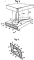
- FIG. 3 a single nozzle guide vane 12 is shown with the leading edge end of the inner platform cut-away for the purpose of illustrating the inner platform 16 an inner platform internal cavity 41.
- the inner platform comprises a pressure wall 42 and a suction wall 44 on the respective pressure and suction sides of the aerofoil on the aerofoil side of the cavity.
- the other side of the platform comprises an under platform wall 43 which is provided with a plurality of impingement cooling holes 46 for directing cooling air admitted from the plenum region 36 into the platform cavity 41 as high velocity impingement jets against the platform pressure and suction wall surfaces in the cavity.
- the platform cavity is divided into two chambers, including a first chamber 48 for receiving cooling air from the plenum 36 for cooling the platform pressure wall 42, and a second chamber 50 for receiving cooling air also from the plenum 36 for cooling the platform suction wall 44.
- the first chamber 48 is in flow communication with an aerofoil section cavity 52 which is positioned adjacent to a leading edge aerofoil section internal cavity 54 and the aerofoil trailing edge 55.
- the platform cavity is divided by means of a first internal wall 58 which is substantially coincident with the aerofoil suction wall in the spanwise direction of the vane and a second wall 60 which extends from an aerofoil leading edge region of the wall 58 to the suction side edge 61 of the platform.
- the cavity dividing walls 58 and 60 divide the cavity into the two chambers 48 and 50 with the chamber 48 occupying the region forward of the aerofoil leading edge and the region of the pressure wall 42, while the chamber 50 occupies the aerofoil trailing edge region and the suction surface wall 44.
- a further wall 62 is provided in the cavity 41 around the pressure surface side of the leading edge internal aerofoil cavity 54.
- the aerofoil cavity 54 is fed independently of the platform cavity chambers 48 and 50 with cooling air directly from the plenum region 36 on the underside of the platform.
- the division of the cavity 41 is shown schematically in the drawing of Figure 3 where the 3-D hatched block 57 represents the part of the platform corresponding to the region of the second chamber 50.
- the size, shape and spacing of the impingement holes 46 into the chamber 48 is such that the holes generate relatively weak impingement jets of cooling air against the platform pressure wall 42 on the opposite side of the chamber, that is to say the pressure drop across the holes is relatively small in comparison to the overall pressure of the cooling air admitted into the chamber 48 from the plenum 36.
- the impingement holes 49 that feed the trailing edge cavity 50 are of a shape, size and spacing suitable for generating relatively high velocity impingement jets of cooling air against the platform suction and trailing edge wall 44.
- the relatively high pressure drop across the holes 49 in the chamber 50 enables a relatively low flow of cooling fluid to be used to cool the platform suction and trailing edge wall 44.
- the cooling air entering the second chamber 50 exits the chamber through an array of parallel exhaust slots 63 in the trailing edge 66 of the platform.
- the cooling air entering the first chamber 48 exits the chamber with a relatively high pressure into the aerofoil internal cavity 52 through which it is conveyed with its thermal capacity being used to cool the aerofoil suction and pressure walls as it flows along the aerofoil section.
- the suction side of the platform cooling air is exhausted through the trailing edge slots 62 while the pressure side platform cooling air exhausts into the cavity 52 in the aerofoil.
- the air from the chamber 48 is used to supplement the main aerofoil cooling air before being exhausted through film cooling holes or trailing edge slots in the aerofoil section.
- the cooling air pressure in the cavity chamber 48 is maintained higher than the pressure of the turbine gases acting on the platform wall 42.
- the pressure drop over the impingement holes 46 which admit the cooling air into the chamber 48 is therefore relatively low so that a relatively high pressure can be maintained in the chamber 48.
- this cooling air is used to further cool the aerofoil section rather than being discarded since the cooling air has additional thermal capacity for cooling the aerofoil once it has been used for impingement cooling of the platform pressure wall.
- Film cooling holes may also be provided in the suction wall 44 of the platform. In contrast to the film cooling holes which may be provided in the pressure wall, the film cooling holes in the suction wall exhaust at a much lower pressure.
- the impingement holes 49 that admit cooling air into the suction side platform chamber 50 have a much greater pressure drop for generating relatively high velocity impingement jets of cooling air compared with the holes 46 in the chamber 48. As the cooling air requirement of the chamber 50 is relatively low the cooling air admitted into this chamber can be exhausted through the platform trailing edge slots 63 without significant reduction in cooling effectiveness.
- the invention contemplates embodiments where the cooled aerofoil platform is part of a turbine rotor blade or a nozzle guide vane.
- the invention contemplates embodiments where both the inner and outer platforms of a nozzle guide vane are provided with an impingement cooling arrangement as described with reference to the inner platform in the drawing of Figure 3 .
Landscapes
- Engineering & Computer Science (AREA)
- Mechanical Engineering (AREA)
- General Engineering & Computer Science (AREA)
- Turbine Rotor Nozzle Sealing (AREA)
Claims (6)
- Turbinenlaufschaufel oder Turbinenrotorblatt für ein Gasturbinentriebwerk, umfassend ein Blattprofil (20), das eine Druckwand (26), eine Saugwand (28) und zumindest einen Hohlraum (52, 54) zwischen der Druck- und der Saugwand (26, 28) zur Beförderung von Kühlluft durch das Blattprofil (20) und zumindest eine Blattprofilplattform (16, 18) benachbart und im Allgemeinen senkrecht zu dem Blattprofil (20) aufweist; wobei die Plattform zumindest einen inneren Hohlraum (41) mit einer Druckwand (42) und einer Saugwand (44) auf der Druck- bzw. Saugseite des Blattprofils (20) aufweist, wobei der Hohlraum (41) der Plattform durch Innenwände (58, 60) in zumindest zwei Kammern (48, 50) auf der Druck- und der Saugseite des Blattprofils (20) geteilt wird, in welchen eine erste Kammer (48) Kühlluft zur Kühlung der Druckwand (42) der Plattform aufnimmt und eine zweite Kammer (50) Kühlluft zur Kühlung der Saugwand (44) der Plattform aufnimmt, wobei die erste Kammer in Strömungskommunikation mit dem Hohlraum des Blattprofils steht, um zumindest einen Teil der Kühlluft, die in die erste Kammer eintritt, in den Hohlraum des Blattprofils zu entlassen; wobei eine Wand (43) auf einer gegenüberliegenden Seite des Hohlraums (41) der Plattform zu der Druck- und Saugwand (42, 44) der Plattform mit einer Vielzahl von Prallkühllöchern (46, 49) versehen ist, um Kühlluft in den Hohlraum (41) der Plattform aus einer gemeinsamen Quelle (36) einzuleiten;
die Druckwand (42) der Plattform ist mit Filmkühllöchern (40) zur Beförderung von Kühlluft aus der ersten Kammer (48) zu der Außenfläche der Druckwand (42) der Plattform versehen, um einen Kühlluftfilm über der verwendeten Außenfläche bereitzustellen, und die Saugwand (44) der Plattform ist mit weiteren Filmkühllöchern (40) zur Beförderung von Kühlluft aus der zweiten Kammer (50) zu der Außenfläche der Saugwand (44) der Plattform versehen, um einen Kühlluftfilm über der verwendeten Außenfläche bereitzustellen; ein erster Satz an Prallkühllöchern (46) in der Wand (43) ermöglicht den Eintritt von Kühlluft in die erste Kammer (48) des Hohlraums (41) der Plattform und ein zweiter Satz an Prallkühllöchern (49) ermöglicht den Eintritt von Kühlluft in die zweite Kammer (50), und der erste und der zweite Satz an Prallkühllöchern (46, 49) sind derart bemessen und beabstandet, dass bei der Verwendung Kühlluft, die in die erste Kammer (48) eintritt, einen höheren Betriebsdruck aufweist als Kühlluft, die in die zweite Kammer (50) eintritt. - Turbinenlaufschaufel oder Turbinenrotorblatt nach Anspruch 1, ferner dadurch gekennzeichnet, dass der erste und der zweite Satz an Prallkühlungslöchern (46, 49) derart bemessen und beabstandet sind, dass bei der Verwendung die Durchflussrate der Kühlluft durch die ersten Löcher (46) in die erste Kammer (48) höher ist als die Durchflussrate der Kühlluft durch die zweiten Löcher (49) in die zweite Kammer (50).
- Turbinenlaufschaufel oder Turbinenrotorblatt nach Anspruch 1 oder 2, ferner dadurch gekennzeichnet, dass die zweite Kammer (50) eine Vielzahl von Kühlluft-Austrittsöffnungen (63) an einer nachgelagerten oder Hinterkante (66) der Plattform (16, 18) umfasst.
- Turbinenlaufschaufel oder Turbinenrotorblatt nach Anspruch 3, ferner dadurch gekennzeichnet, dass die Austrittsöffnungen (63) eine Vielzahl von Kühlluft-Austrittsschlitzen umfassen.
- Turbinenlaufschaufel oder Turbinenrotorblatt nach einem der vorhergehenden Ansprüche, ferner dadurch gekennzeichnet, dass das Blattprofil (20) eine erste und eine zweite Plattform (16, 18) an in Spannweitenrichtung gegenüberliegenden Enden des Blattprofils umfasst, um radiale innere und äußere Deckbänder in einem Array aus umlaufend beabstandeten Turbinenlaufschaufeln oder Turbinenrotorblättern in einem Gasturbinentriebwerk auszubilden.
- Turbinenlaufschaufel oder Turbinenrotorblatt nach einem der vorhergehenden Ansprüche, ferner dadurch gekennzeichnet, dass in der ersten und/oder zweiten Kammer eine Vielzahl von Vorsprüngen bereitgestellt ist, um die Kühloberfläche der Kammer(n) zu vergrößern.
Applications Claiming Priority (2)
| Application Number | Priority Date | Filing Date | Title |
|---|---|---|---|
| GB0312867 | 2003-06-04 | ||
| GB0312867A GB2402442B (en) | 2003-06-04 | 2003-06-04 | Cooled nozzled guide vane or turbine rotor blade platform |
Publications (3)
| Publication Number | Publication Date |
|---|---|
| EP1484476A2 EP1484476A2 (de) | 2004-12-08 |
| EP1484476A3 EP1484476A3 (de) | 2007-05-23 |
| EP1484476B1 true EP1484476B1 (de) | 2016-06-08 |
Family
ID=9959331
Family Applications (1)
| Application Number | Title | Priority Date | Filing Date |
|---|---|---|---|
| EP04252296.1A Expired - Lifetime EP1484476B1 (de) | 2003-06-04 | 2004-04-19 | Kühlung der Plattform einer Gasturbinenlaufschaufel oder -leitschaufel |
Country Status (3)
| Country | Link |
|---|---|
| US (1) | US7001141B2 (de) |
| EP (1) | EP1484476B1 (de) |
| GB (1) | GB2402442B (de) |
Families Citing this family (23)
| Publication number | Priority date | Publication date | Assignee | Title |
|---|---|---|---|---|
| US7452184B2 (en) * | 2004-12-13 | 2008-11-18 | Pratt & Whitney Canada Corp. | Airfoil platform impingement cooling |
| US7806650B2 (en) * | 2006-08-29 | 2010-10-05 | General Electric Company | Method and apparatus for fabricating a nozzle segment for use with turbine engines |
| US7762773B2 (en) * | 2006-09-22 | 2010-07-27 | Siemens Energy, Inc. | Turbine airfoil cooling system with platform edge cooling channels |
| US7766609B1 (en) | 2007-05-24 | 2010-08-03 | Florida Turbine Technologies, Inc. | Turbine vane endwall with float wall heat shield |
| US8292587B2 (en) * | 2008-12-18 | 2012-10-23 | Honeywell International Inc. | Turbine blade assemblies and methods of manufacturing the same |
| GB2467790B (en) * | 2009-02-16 | 2011-06-01 | Rolls Royce Plc | Vane |
| US8851845B2 (en) | 2010-11-17 | 2014-10-07 | General Electric Company | Turbomachine vane and method of cooling a turbomachine vane |
| US8870525B2 (en) | 2011-11-04 | 2014-10-28 | General Electric Company | Bucket assembly for turbine system |
| US8845289B2 (en) | 2011-11-04 | 2014-09-30 | General Electric Company | Bucket assembly for turbine system |
| US8840370B2 (en) | 2011-11-04 | 2014-09-23 | General Electric Company | Bucket assembly for turbine system |
| US9500099B2 (en) | 2012-07-02 | 2016-11-22 | United Techologies Corporation | Cover plate for a component of a gas turbine engine |
| US9091180B2 (en) | 2012-07-19 | 2015-07-28 | Siemens Energy, Inc. | Airfoil assembly including vortex reducing at an airfoil leading edge |
| US10041357B2 (en) | 2015-01-20 | 2018-08-07 | United Technologies Corporation | Cored airfoil platform with outlet slots |
| EP3273002A1 (de) * | 2016-07-18 | 2018-01-24 | Siemens Aktiengesellschaft | Prallkühlung einer schaufelplattform |
| US20190085706A1 (en) * | 2017-09-18 | 2019-03-21 | General Electric Company | Turbine engine airfoil assembly |
| US10774662B2 (en) | 2018-07-17 | 2020-09-15 | Rolls-Royce Corporation | Separable turbine vane stage |
| US11180998B2 (en) | 2018-11-09 | 2021-11-23 | Raytheon Technologies Corporation | Airfoil with skincore passage resupply |
| US11248470B2 (en) | 2018-11-09 | 2022-02-15 | Raytheon Technologies Corporation | Airfoil with core cavity that extends into platform shelf |
| US11021966B2 (en) * | 2019-04-24 | 2021-06-01 | Raytheon Technologies Corporation | Vane core assemblies and methods |
| CN114439551B (zh) * | 2020-10-30 | 2024-05-10 | 中国航发商用航空发动机有限责任公司 | 航空发动机 |
| CN113202567B (zh) * | 2021-05-25 | 2022-10-28 | 中国航发沈阳发动机研究所 | 一种高压涡轮导向冷却叶片缘板的冷却结构设计方法 |
| CN115506856A (zh) * | 2022-09-16 | 2022-12-23 | 中国航发湖南动力机械研究所 | 一种复合冷却结构的涡轮导向叶片 |
| CN115889125A (zh) * | 2023-02-02 | 2023-04-04 | 中国航发沈阳发动机研究所 | 一种航空发动机双层壁涡轮叶片表面示温涂料喷涂方法 |
Family Cites Families (17)
| Publication number | Priority date | Publication date | Assignee | Title |
|---|---|---|---|---|
| US4040767A (en) * | 1975-06-02 | 1977-08-09 | United Technologies Corporation | Coolable nozzle guide vane |
| DE3003347A1 (de) * | 1979-12-20 | 1981-06-25 | BBC AG Brown, Boveri & Cie., Baden, Aargau | Gekuehlte wand |
| US4712979A (en) * | 1985-11-13 | 1987-12-15 | The United States Of America As Represented By The Secretary Of The Air Force | Self-retained platform cooling plate for turbine vane |
| US5201847A (en) * | 1991-11-21 | 1993-04-13 | Westinghouse Electric Corp. | Shroud design |
| FR2692318B1 (fr) * | 1992-06-11 | 1994-08-19 | Snecma | Aubage fixe de distribution des gaz chauds d'une turbo-machine. |
| US5382135A (en) * | 1992-11-24 | 1995-01-17 | United Technologies Corporation | Rotor blade with cooled integral platform |
| US5252026A (en) * | 1993-01-12 | 1993-10-12 | General Electric Company | Gas turbine engine nozzle |
| US5344283A (en) * | 1993-01-21 | 1994-09-06 | United Technologies Corporation | Turbine vane having dedicated inner platform cooling |
| US5413458A (en) * | 1994-03-29 | 1995-05-09 | United Technologies Corporation | Turbine vane with a platform cavity having a double feed for cooling fluid |
| JP2971386B2 (ja) * | 1996-01-08 | 1999-11-02 | 三菱重工業株式会社 | ガスタービン静翼 |
| US5915923A (en) * | 1997-05-22 | 1999-06-29 | Mitsubishi Heavy Industries, Ltd. | Gas turbine moving blade |
| CA2262064C (en) * | 1998-02-23 | 2002-09-03 | Mitsubishi Heavy Industries, Ltd. | Gas turbine moving blade platform |
| JPH11257003A (ja) * | 1998-03-06 | 1999-09-21 | Mitsubishi Heavy Ind Ltd | インピンジメント冷却装置 |
| US6261054B1 (en) * | 1999-01-25 | 2001-07-17 | General Electric Company | Coolable airfoil assembly |
| US6254333B1 (en) * | 1999-08-02 | 2001-07-03 | United Technologies Corporation | Method for forming a cooling passage and for cooling a turbine section of a rotary machine |
| US6508620B2 (en) * | 2001-05-17 | 2003-01-21 | Pratt & Whitney Canada Corp. | Inner platform impingement cooling by supply air from outside |
| FR2833035B1 (fr) * | 2001-12-05 | 2004-08-06 | Snecma Moteurs | Plate-forme d'aube de distributeur pour moteur a turbine a gaz |
-
2003
- 2003-06-04 GB GB0312867A patent/GB2402442B/en not_active Expired - Fee Related
-
2004
- 2004-04-19 EP EP04252296.1A patent/EP1484476B1/de not_active Expired - Lifetime
- 2004-04-23 US US10/830,110 patent/US7001141B2/en not_active Expired - Lifetime
Also Published As
| Publication number | Publication date |
|---|---|
| US20040247435A1 (en) | 2004-12-09 |
| EP1484476A2 (de) | 2004-12-08 |
| GB2402442B (en) | 2006-05-31 |
| GB2402442A (en) | 2004-12-08 |
| EP1484476A3 (de) | 2007-05-23 |
| GB0312867D0 (en) | 2003-07-09 |
| US7001141B2 (en) | 2006-02-21 |
Similar Documents
| Publication | Publication Date | Title |
|---|---|---|
| EP1484476B1 (de) | Kühlung der Plattform einer Gasturbinenlaufschaufel oder -leitschaufel | |
| US6607355B2 (en) | Turbine airfoil with enhanced heat transfer | |
| EP1106781B1 (de) | Gekühlte Stator- oder Rotorschaufel für eine Turbomaschine | |
| US6402471B1 (en) | Turbine blade for gas turbine engine and method of cooling same | |
| JP4719122B2 (ja) | 逆冷却タービンノズル | |
| EP0330601B1 (de) | Kühlung einer Gasturbinenschaufel | |
| EP1205636B1 (de) | Turbinenschaufel einer Gasturbine sowie Verfahren zur Kühlung der Schaufel | |
| EP0929734B1 (de) | Turbinenleitschaufelkühlung | |
| EP1921272B1 (de) | Luftgekühlte Schaufel für eine Gasturbine | |
| EP1001137B1 (de) | Gasturbinenschaufel mit serpentinenförmigen Kühlkanälen | |
| US7435053B2 (en) | Turbine blade cooling system having multiple serpentine trailing edge cooling channels | |
| EP0971095B1 (de) | Kühlbare Schaufel für Gasturbinen | |
| EP1041247B1 (de) | Gasturbinenschaufel mit einem offenen Kühlkreislauf | |
| US6174134B1 (en) | Multiple impingement airfoil cooling | |
| EP2329112B1 (de) | Kühlsystem für gasturbinen | |
| US7497655B1 (en) | Turbine airfoil with near-wall impingement and vortex cooling | |
| EP1022432B1 (de) | Gekühlte Gasturbinenschaufel | |
| US5591002A (en) | Closed or open air cooling circuits for nozzle segments with wheelspace purge | |
| US7004720B2 (en) | Cooled turbine vane platform | |
| EP2119872B1 (de) | Interne Kühlungskonfiguration für Turbinenschaufel | |
| EP1106782B1 (de) | Gekühlte Gasturbinenschaufel und deren Herstellungsmethode | |
| JP4436500B2 (ja) | エーロフォイルの前縁隔離冷却 | |
| IL35196A (en) | Fluid cooled vane assembly | |
| US7281895B2 (en) | Cooling system for a turbine vane | |
| US6357999B1 (en) | Gas turbine engine internal air system |
Legal Events
| Date | Code | Title | Description |
|---|---|---|---|
| PUAI | Public reference made under article 153(3) epc to a published international application that has entered the european phase |
Free format text: ORIGINAL CODE: 0009012 |
|
| AK | Designated contracting states |
Kind code of ref document: A2 Designated state(s): AT BE BG CH CY CZ DE DK EE ES FI FR GB GR HU IE IT LI LU MC NL PL PT RO SE SI SK TR |
|
| AX | Request for extension of the european patent |
Extension state: AL HR LT LV MK |
|
| PUAL | Search report despatched |
Free format text: ORIGINAL CODE: 0009013 |
|
| AK | Designated contracting states |
Kind code of ref document: A3 Designated state(s): AT BE BG CH CY CZ DE DK EE ES FI FR GB GR HU IE IT LI LU MC NL PL PT RO SE SI SK TR |
|
| AX | Request for extension of the european patent |
Extension state: AL HR LT LV MK |
|
| 17P | Request for examination filed |
Effective date: 20071115 |
|
| AKX | Designation fees paid |
Designated state(s): DE FR |
|
| 17Q | First examination report despatched |
Effective date: 20080228 |
|
| RAP1 | Party data changed (applicant data changed or rights of an application transferred) |
Owner name: ROLLS-ROYCE PLC |
|
| GRAP | Despatch of communication of intention to grant a patent |
Free format text: ORIGINAL CODE: EPIDOSNIGR1 |
|
| GRAS | Grant fee paid |
Free format text: ORIGINAL CODE: EPIDOSNIGR3 |
|
| INTG | Intention to grant announced |
Effective date: 20160225 |
|
| GRAA | (expected) grant |
Free format text: ORIGINAL CODE: 0009210 |
|
| AK | Designated contracting states |
Kind code of ref document: B1 Designated state(s): DE FR |
|
| REG | Reference to a national code |
Ref country code: DE Ref legal event code: R096 Ref document number: 602004049418 Country of ref document: DE |
|
| REG | Reference to a national code |
Ref country code: DE Ref legal event code: R097 Ref document number: 602004049418 Country of ref document: DE |
|
| PLBE | No opposition filed within time limit |
Free format text: ORIGINAL CODE: 0009261 |
|
| STAA | Information on the status of an ep patent application or granted ep patent |
Free format text: STATUS: NO OPPOSITION FILED WITHIN TIME LIMIT |
|
| REG | Reference to a national code |
Ref country code: FR Ref legal event code: PLFP Year of fee payment: 14 |
|
| 26N | No opposition filed |
Effective date: 20170309 |
|
| PGFP | Annual fee paid to national office [announced via postgrant information from national office to epo] |
Ref country code: DE Payment date: 20170427 Year of fee payment: 14 |
|
| REG | Reference to a national code |
Ref country code: FR Ref legal event code: PLFP Year of fee payment: 15 |
|
| REG | Reference to a national code |
Ref country code: DE Ref legal event code: R119 Ref document number: 602004049418 Country of ref document: DE |
|
| PG25 | Lapsed in a contracting state [announced via postgrant information from national office to epo] |
Ref country code: DE Free format text: LAPSE BECAUSE OF NON-PAYMENT OF DUE FEES Effective date: 20181101 |
|
| PGFP | Annual fee paid to national office [announced via postgrant information from national office to epo] |
Ref country code: FR Payment date: 20190425 Year of fee payment: 16 |
|
| PG25 | Lapsed in a contracting state [announced via postgrant information from national office to epo] |
Ref country code: FR Free format text: LAPSE BECAUSE OF NON-PAYMENT OF DUE FEES Effective date: 20200430 |