EP1484492A2 - Vorrichtung und Verfahren zur Steuerung der zugeführten Brennstoffmenge einer Brennkraftmaschine - Google Patents
Vorrichtung und Verfahren zur Steuerung der zugeführten Brennstoffmenge einer Brennkraftmaschine Download PDFInfo
- Publication number
- EP1484492A2 EP1484492A2 EP04013042A EP04013042A EP1484492A2 EP 1484492 A2 EP1484492 A2 EP 1484492A2 EP 04013042 A EP04013042 A EP 04013042A EP 04013042 A EP04013042 A EP 04013042A EP 1484492 A2 EP1484492 A2 EP 1484492A2
- Authority
- EP
- European Patent Office
- Prior art keywords
- injection amount
- amount
- fuel injection
- engine
- limit value
- Prior art date
- Legal status (The legal status is an assumption and is not a legal conclusion. Google has not performed a legal analysis and makes no representation as to the accuracy of the status listed.)
- Withdrawn
Links
- 239000000446 fuel Substances 0.000 title claims abstract description 121
- 238000002485 combustion reaction Methods 0.000 title claims abstract description 16
- 238000000034 method Methods 0.000 title claims description 55
- 238000002347 injection Methods 0.000 claims abstract description 121
- 239000007924 injection Substances 0.000 claims abstract description 121
- 230000000153 supplemental effect Effects 0.000 claims abstract description 74
- 230000005540 biological transmission Effects 0.000 claims description 25
- 230000035939 shock Effects 0.000 claims description 20
- 230000001276 controlling effect Effects 0.000 claims description 7
- 230000001105 regulatory effect Effects 0.000 claims description 5
- 230000000994 depressogenic effect Effects 0.000 claims description 4
- 230000008569 process Effects 0.000 description 44
- 230000008901 benefit Effects 0.000 description 10
- 230000008859 change Effects 0.000 description 8
- 238000012937 correction Methods 0.000 description 4
- 238000010586 diagram Methods 0.000 description 3
- 239000002826 coolant Substances 0.000 description 2
- 238000004891 communication Methods 0.000 description 1
- 230000003247 decreasing effect Effects 0.000 description 1
- 238000004880 explosion Methods 0.000 description 1
- 230000009467 reduction Effects 0.000 description 1
Images



Classifications
-
- F—MECHANICAL ENGINEERING; LIGHTING; HEATING; WEAPONS; BLASTING
- F02—COMBUSTION ENGINES; HOT-GAS OR COMBUSTION-PRODUCT ENGINE PLANTS
- F02D—CONTROLLING COMBUSTION ENGINES
- F02D41/00—Electrical control of supply of combustible mixture or its constituents
- F02D41/02—Circuit arrangements for generating control signals
- F02D41/04—Introducing corrections for particular operating conditions
- F02D41/08—Introducing corrections for particular operating conditions for idling
- F02D41/083—Introducing corrections for particular operating conditions for idling taking into account engine load variation, e.g. air-conditionning
-
- F—MECHANICAL ENGINEERING; LIGHTING; HEATING; WEAPONS; BLASTING
- F02—COMBUSTION ENGINES; HOT-GAS OR COMBUSTION-PRODUCT ENGINE PLANTS
- F02D—CONTROLLING COMBUSTION ENGINES
- F02D2250/00—Engine control related to specific problems or objectives
- F02D2250/18—Control of the engine output torque
- F02D2250/26—Control of the engine output torque by applying a torque limit
-
- F—MECHANICAL ENGINEERING; LIGHTING; HEATING; WEAPONS; BLASTING
- F02—COMBUSTION ENGINES; HOT-GAS OR COMBUSTION-PRODUCT ENGINE PLANTS
- F02D—CONTROLLING COMBUSTION ENGINES
- F02D2250/00—Engine control related to specific problems or objectives
- F02D2250/28—Control for reducing torsional vibrations, e.g. at acceleration
-
- F—MECHANICAL ENGINEERING; LIGHTING; HEATING; WEAPONS; BLASTING
- F02—COMBUSTION ENGINES; HOT-GAS OR COMBUSTION-PRODUCT ENGINE PLANTS
- F02D—CONTROLLING COMBUSTION ENGINES
- F02D41/00—Electrical control of supply of combustible mixture or its constituents
- F02D41/02—Circuit arrangements for generating control signals
- F02D41/04—Introducing corrections for particular operating conditions
- F02D41/12—Introducing corrections for particular operating conditions for deceleration
-
- F—MECHANICAL ENGINEERING; LIGHTING; HEATING; WEAPONS; BLASTING
- F02—COMBUSTION ENGINES; HOT-GAS OR COMBUSTION-PRODUCT ENGINE PLANTS
- F02D—CONTROLLING COMBUSTION ENGINES
- F02D41/00—Electrical control of supply of combustible mixture or its constituents
- F02D41/02—Circuit arrangements for generating control signals
- F02D41/04—Introducing corrections for particular operating conditions
- F02D41/12—Introducing corrections for particular operating conditions for deceleration
- F02D41/123—Introducing corrections for particular operating conditions for deceleration the fuel injection being cut-off
-
- F—MECHANICAL ENGINEERING; LIGHTING; HEATING; WEAPONS; BLASTING
- F02—COMBUSTION ENGINES; HOT-GAS OR COMBUSTION-PRODUCT ENGINE PLANTS
- F02D—CONTROLLING COMBUSTION ENGINES
- F02D41/00—Electrical control of supply of combustible mixture or its constituents
- F02D41/30—Controlling fuel injection
- F02D41/32—Controlling fuel injection of the low pressure type
- F02D41/34—Controlling fuel injection of the low pressure type with means for controlling injection timing or duration
Definitions
- the present invention relates to a fuel supply amount controller of an internal combustion engine that regulating the fuel supply amount, thereby directly or indirectly adjusting the output torque. Specifically, the present invention relates to a fuel supply amount controller that, in accordance with a fail-safe limit value set correspondingly to an operation state of an internal combustion engine, restricts a fuel supply amount requested for the internal combustion engine. The present invention also pertains to a method for controlling the controller.
- Japanese Laid-Open Patent Publication No. 2002-39004 discloses an internal combustion engine that restricts a fuel supply amount, which is a fuel injection amount, using a fail-safe limit value for performing a fail-safe procedure against errors in the computation of the fuel injection amount. Specifically, when a specific operational state, for example, a state in which an accelerator pedal is not depressed, continues for a standby period, the engine of the publication performs a procedure for restricting the fuel injection amount in accordance with a fail-safe limit value.
- the excessive fuel injection amount is returned to a value that corresponds to a state where the accelerator pedal is not depressed at all by releasing the accelerator pedal.
- a control system which requests increase of a fuel injection amount in order to moderate a shock at the time of shift-down performed by an automatic transmission under deceleration.
- the control system functions after a non-depressed state of an accelerator pedal continues for a standby time, even if an increase of fuel injection amount is requested for moderating a shock due to gear shifting is executed and the request is reflected on the computation of the fuel injection amount, an actual fuel injection amount is restricted correspondingly to a depression degree of the accelerator pedal with the a fail-safe limit value at the final stage for setting the fuel injection amount. Therefore, the fuel injection amount is not increased by a necessary amount and the shock due to gear shifting may not be sufficiently reduced.
- the present invention provides a controller for controlling the amount of fuel supplied to an internal combustion engine of a vehicle. Output torque of the engine is adjusted by regulating the fuel supply amount.
- the controller restricts the fuel supply amount, which is requested for the engine, in accordance with a fail-safe limit value set correspondingly to an operation state of the engine.
- the controller includes changing means. When a supplemental fuel injection amount, which is requested for causing the engine to generate output torque required for purposes other than driving the vehicle, is set, the changing means causes the limit value to be equal to or to approach the supplemental fuel injection amount if the limit value is less than the supplemental fuel injection amount.
- a method for controlling the amount of fuel supplied to an internal combustion engine of a vehicle is provided. Output torque of the engine is adjusted by regulating the fuel supply amount.
- the method includes a step of restricting the fuel supply amount, which is requested for the engine, in accordance with a fail-safe limit value set correspondingly to an operation state of the engine.
- the method further includes steps of setting a supplemental fuel injection amount for causing the engine to generate output torque required for purposes other than driving the vehicle; and causing the limit value to be equal to or to approach the supplemental fuel injection amount when the limit value is less than the supplemental fuel injection amount.
- FIG. 1 is a block diagram showing an accumulator type diesel engine (common-rail diesel engine) 2, an automatic transmission 4, an ECU (electronic control unit) 6 of the diesel engine 2 and an ECU 8 of the transmission 4.
- the diesel engine 2 is mounted on a vehicle as an automobile engine.
- the diesel engine 2 has cylinders the number of which is, for example, four.
- a fuel injection valve is set to the combustion chamber of each cylinder. Fuel raised up.to a fuel injection pressure is supplied to the fuel injection valves from a common rail. The fuel is injected into each cylinder by opening each fuel injection valve in accordance with a command by the engine ECU 6 for a valve opening period corresponding to a fuel injection amount requested for the diesel engine 2.
- the diesel engine 2 and the automatic transmission 4 are provided with various sensors 10.
- the diesel engine 2 is provided with an accelerator pedal depression degree sensor, an engine speed sensor, a cylinder-distinguishing sensor, a coolant temperature sensor, an intake-air temperature sensor, and fuel pressure sensor.
- the automatic transmission 4 is provided with a speed sensor.
- the engine ECU 6 detects an operation state of the diesel engine 2 and a driving state of a vehicle in accordance with outputs of various sensors 10.
- the engine ECU 6 exchanges commands and data with the transmission ECU 8.
- the engine ECU 6 controls the combustion state of the diesel engine 2 through fuel injection amount control in accordance with these commands and data.
- the automatic transmission 4 is of a torque converter type, which changes speeds by controlling operations of internal rotational members, for example, various gears including a planetary gear, a clutch, and brakes.
- the sensors 10 include a shift position sensor and a turbine speed sensor set to the automatic transmission 4 in addition to the above configuration.
- the transmission ECU 8 detects a request of a driver, an internal state of the automatic transmission 4 and a driving state of a vehicle in accordance with the data on an accelerator pedal depression degree ACCP, an engine speed NE, a shift position, a turbine speed NT, and a vehicle speed V to execute vehicle speed control for the automatic transmission 4. Moreover, the transmission ECU 8 reads a coolant temperature and braking state in the data detected by the engine ECU 6.
- the transmission ECU 8 exchanges commands and data with the engine ECU 6.
- the transmission ECU 8 executes the speed change control of the automatic transmission 4 by switching electromagnetic valves of a hydraulic control circuit 4a in accordance with these commands and data.
- a gear stage of the automatic transmission 4 is determined in accordance with a vehicle speed V and a fuel injection amount (or depression degree of the accelerator pedal ACCP) by using a previously stored speed-change diagram to switch electromagnetic valves of the hydraulic control circuit 4a so as to effectuate the decided gear stage.
- the engine ECU 6 and the transmission ECU 8 are respectively mainly constituted by a microcomputer having a CPU, a ROM, a RAM, a backup RAM, a timer counter, an input interface, and an output interface.
- FIG. 2 shows a flowchart of the process. This control is executed as an interrupt at every constant crank angle (every explosion stroke). A step in the flowchart corresponding to each process is shown by the letter S.
- a base injection amount eqBase is first calculated in accordance with an operation state of the diesel engine 2 by the above sensors 10 (S102).
- the base injection amount eqBase is set by correcting a reference injection amount, that is, a governor injection amount eqgov obtained from the engine speed NE and depression degree of the accelerator pedal ACCP in accordance with a map for reference pattern data shown in FIG. 3. For example, when a load such as air conditioner load is generated on the governor injection amount eqgov, a fuel injection amount correction corresponding to the load or a correction according to learned value obtained at the time of idling speed control (ISC) is executed.
- a load such as air conditioner load
- a correction is executed in which a fuel injection amount requested at the time of shift-down (described below), that is, a supplemental fuel injection amount eqEctu is used as the base injection amount eqBase.
- the base injection amount eqBase is calculated by executing the above various corrections.
- an injection amount before final restriction that is, a prefinal injection amount eqPreFinc is calculated (S104).
- the maximum injection amount eqFull is a value for setting the upper limit of a fuel injection amount to be set correspondingly to the engine speed NE in accordance with the synchronization process (synchronization) to be described later.
- MIN () denotes an operator for extracting a minimum value out of numerals enclosed by parentheses.
- the upper limit of the base injection amount eqBase is restricted in accordance with the expression 1 and set as the prefinal injection amount eqPreFinc.
- a standby time elapses while the depression degree of the accelerator pedal ACCP is equal to [0], that is, an accelerator pedal is released (S106).
- an accelerator pedal is completely released, it is possible to estimate that a driver performs a deceleration operation.
- the changing speed of the base injection amount eqBase is restricted to prevent a shock, for example a deceleration shock from occurring due to sudden reduction of a fuel injection amount through a pedal operation. Therefore, even if a deceleration operation is performed by a driver, a deceleration shock may occur when suddenly decreasing a fuel injection amount by immediately adding a new restriction to the fuel injection amount. Therefore, a standby time is set for the determination in step S106.
- the value of the prefinal injection amount eqPreFinc is set to a final fuel injection amount (final injection amount) eqFinc (S108) and the process is temporarily ended.
- the final injection amount eqFinc is set, valve-opening control for the fuel injection valves is executed by the engine ECU 6 so that the amount of fuel equivalent to the final injection amount eqFinc is injected into the combustion chamber of the diesel engine 2.
- the supplemental amount eqEctu is a requested fuel injection amount set in a synchronization process (described later). That is, the supplemental amount eqEctu is a fuel injection amount to be increased that is set as a request value at the timing in a shift-down fuel amount increasing period after increase of a fuel injection amount is requested at the time of shift-down by the transmission ECU 8.
- the supplemental amount eqEctu is a fuel injection amount set to prevent a deceleration shock at the time of shift-down.
- the supplemental amount eqEctu is set in accordance with the target engine speed NEt set correspondingly to shift-down control in accordance with the map shown in FIG. 4.
- a fuel-injection-amount limit value when the accelerator pedal is released is a fail-safe limit value for preventing an excessive fuel amount from being injected when a standby time elapses under the accelerator pedal released state.
- the first limit value eqAcgurd is set in accordance with the engine speed NE by using the map shown in FIG. 5.
- the first limit value eqAcgurd is set to 0 (mm 3 /stroke) or less in order to cut fuel at the engine high-speed side.
- the upper limit of the prefinal injection amount eqPreFinc is restricted in accordance with the first limit value eqAcgurd and set as the final injection amount eqFinc.
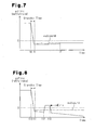
- FIG. 7 shows a state in which the prefinal injection amount eqPreFinc exceeds the first limit value eqAcgurd due to any reason at t2. However, the final injection amount eqFinc does not exceed the value of the first limit value eqAcgurd.
- MAX () denotes an operator for extracting a maximum value out of numerals enclosed by parentheses.
- the prefinal injection amount eqPreFinc is restricted by greater one of the supplemental amount eqEctu and first limit value eqAcgurd and set as the final injection amount eqFinc.
- the supplemental amount eqEctu which is greater than the first limit value eqAcgurd, is set for shift-down at t12
- the final injection amount eqFinc is limited by the supplemental amount eqEctu in accordance with the above expression 3. Therefore, it is possible to increase a fuel amount so as to prevent a deceleration shock at the time of shift-down.
- FIG. 6 shows the synchronization process for setting the maximum injection amount eqFull and supplemental amount eqEctu.
- the process is repeatedly executed in the engine ECU 6 at a short-time period.
- the maximum injection amount eqFull is first obtained in accordance with the engine speed NE from a maximum injection amount eqFull map shown by an alternate long and short dash line by superimposing the map in FIG. 3 (S202).
- S204 it is determined whether a fuel amount increase request is generated at the time of shift-down by the transmission ECU 8 (S204).
- the supplemental amount eqEctu is cleared, that is, an unset state is set (S208) and the process is temporarily ended.
- the fuel amount increase period is a period in which it is necessary to restrain a shock at the time of shift-down by increasing a torque during a speed change, which is set in accordance with, for example, the depression degree of the accelerator pedal ACCP, the vehicle speed V, the turbine speed NT, or the shift state.
- the supplemental amount eqEctu is set in accordance with the target engine speed NEt by using the above-described map in FIG. 4 (S210).
- the supplemental amount eqEctu is set to the base injection amount eqBase in step S102 of the fuel injection amount control process (FIG. 2).
- a fail-safe limit value is raised to the supplemental amount eqEctu in step S114. Therefore, the engine ECU 6 executes fuel injection according to the supplemental amount eqEctu.
- steps S204 to S210 of the synchronization process correspond to the process by a system for setting a requested fuel supply amount for output torques other than the torque for driving the vehicle.
- steps S110 and S114 of the fuel injection amount control process correspond to the process by fail-safe limit-value changing means.
- the above first embodiment has the following advantage.
- the supplemental amount eqEctu is set (YES in S110 in FIG. 2)
- the first limit value eqAcgurd is compared with the supplemental amount eqEctu by the engine ECU 6. Then, when eqAcgurd is smaller than eqEctu, the supplemental amount eqEctu is set as a limit value instead of the first limit value eqAcgurd (S114). Therefore, when a control system for preventing a shock at the time of shift-down requires the supplemental amount eqEctu, the supplemental amount eqEctu is realized.
- the supplemental amount eqEctu is not used as a limit value but the final injection amount eqFinc is limited by the sufficiently small first limit value eqAcgurd (S112). Therefore, no problem occurs in fail safe.
- the second embodiment executes a fuel injection amount control process in FIG. 9 instead of the fuel injection amount control process (FIG. 2) by the fist embodiment.
- Other configurations are the same as those of the first embodiment.
- the process in FIG. 9 sets a new accelerator released shift-down fuel injection amount limit value, that is, a second limit value eqKgurd when setting the supplemental amount eqEctu and uses the second limit value eqKgurd as a fail-safe limit value at the time of shift-down.
- steps S302 to S312 in FIG. 9 are the same as the processes in steps S102 to S112 in FIG. 2. However, the processes (S314 to S318) when the supplemental amount eqEctu is set (YES in S310) are different from the case of the first embodiment.
- step S310 when YES is determined in step S310, it is determined whether eqAcgurd is smaller than eqEctu (S314).
- eqAcgurd is equal to or greater than eqEctu, it is not necessary to change first limit value eqAcgurd. Therefore, the final injection amount eqFinc is calculated in accordance with the expression 2 described for the first embodiment (S312). Therefore, the final injection amount eqFinc is limited by the first limit value eqAcgurd.
- a limit value increase amount Deq is set as shown in the following expression 5.
- the coefficient k ranges between 0 and 1 (both excluded) and it serves as a coefficient for setting the second limit value eqKgurd so as to meet the inequality eqAcgurd ⁇ eqKgurd ⁇ eqEctu.
- k is set to 0.5.
- the second limit value eqKgurd thus obtained is smaller than the supplemental amount eqEctu, it is set to a value greater than the first limit value eqAcgurd.
- the prefinal injection amount eqPreFinc is restricted by the second limit value eqKgurd in accordance with the expression 6 and set as the final injection amount eqFinc.
- steps S310, S314, S316, and S318 of the fuel injection amount control process correspond to the process by fail-safe limit-value change means.
- the above-described second embodiment has the following advantage.
- the first limit value eqAcgurd is compared with the supplemental amount eqEctu (S314).
- the second limit value eqKgurd which is closer to the supplemental amount eqEctu than the first limit value eqAcgurd is to the supplemental amount eqEctu, is set as a limit value (S316).
- the shift-down fuel amount increase period determined in step S206 of the synchronization process (FIG. 6) does not always accurately coincide with a period in which a speed change shock actually occurs but a time lag may occur between the both periods.
- the supplemental amount eqEctu may be set to the base injection amount eqBase in the period in which it is actually unnecessary to increase a fuel amount for the shift-down.
- the final injection amount eqFinc does not increase up to the supplemental amount eqEctu, but the second limit value eqKgurd becomes the upper limit. Therefore, it is possible to restrain a fuel injection amount for the above time lag.
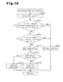
- FIG. 10 executes the synchronization process in FIG. 10 instead of the synchronization process by the first embodiment (FIG. 6).
- Other configurations are the same as those of the first embodiment.
- the process in FIG. 10 limits the supplemental amount eqEctu by a shift-down injection amount limit value, that is, a maximum supplemental amount eqEctuMax.
- steps S402 to S408 in FIG. 10 are the same as the processes in steps S202 to S208 in FIG. 6. However, the processes (S410 to S416) in the shift-down fuel amount increase period (YES in S406) are different from that of the first embodiment.
- pre-restriction shift-down injection amount eqPreEctu is set in accordance with the target engine speed NEt by using a map same as the map in FIG. 4 described for the first embodiment (S410). Then, it is determined whether the eqPreEctu is equal to or smaller than the maximum supplemental amount eqEctuMax to which the maximum fuel injection amount required to prevent a shock at the time of shift-down is set (S412).
- the maximum supplemental amount eqEctuMax corresponds to the maximum requested fuel injection amount and steps S404 to S416 of the synchronization process (FIG. 10) correspond to processes by the control system for setting a requested fuel supply amount for output torques other than the torque for driving the vehicle.
- the above third embodiment has the following advantages.
- the invention may be embodied in the following forms.
- the third embodiment is an example in which the synchronization process in FIG. 10 is combined with the fuel injection amount control process in FIG. 2. However, it is also allowed to combine the synchronization process in FIG. 10 with the fuel injection amount control process in FIG. 9. Thereby, both advantages of the second and third embodiments are obtained.
- a fuel supply system uses a common-rail-type diesel engine.
- a diesel engine using the distribution-type, in-line-type, or other-type fuel injection pump.
- the present invention may be applied to an engine other than a diesel engine.
- the present invention may be applied to an in-cylinder-injection-type gasoline engine when controlling the engine by adjusting a gasoline injection amount at the time of stratified charge combustion.
- a gasoline engine For a gasoline engine, it is allowed to calculate a fuel injection amount in accordance with the depression degree of the accelerator pedal ACCP and the engine speed NE, as the case of the above-described map in FIG. 3. Moreover, it is allowed to calculate a fuel injection amount in accordance with the engine speed NE and a throttle opening degree, which is the opening degree of a throttle valve.
- the output torque of an internal combustion engine is directly adjusted by adjusting a fuel supply amount.
- a fuel injection amount in accordance with an intake air amount and the engine speed NE. That is, it is allowed to adjust indirectly the output torque of an internal combustion engine by adjusting a fuel supply amount.
Landscapes
- Engineering & Computer Science (AREA)
- Chemical & Material Sciences (AREA)
- Combustion & Propulsion (AREA)
- Mechanical Engineering (AREA)
- General Engineering & Computer Science (AREA)
- Electrical Control Of Air Or Fuel Supplied To Internal-Combustion Engine (AREA)
- Control Of Vehicle Engines Or Engines For Specific Uses (AREA)
- Combined Controls Of Internal Combustion Engines (AREA)
- Control Of Transmission Device (AREA)
Applications Claiming Priority (2)
| Application Number | Priority Date | Filing Date | Title |
|---|---|---|---|
| JP2003158653 | 2003-06-03 | ||
| JP2003158653A JP2004360534A (ja) | 2003-06-03 | 2003-06-03 | 内燃機関の燃料供給量制御装置 |
Publications (2)
| Publication Number | Publication Date |
|---|---|
| EP1484492A2 true EP1484492A2 (de) | 2004-12-08 |
| EP1484492A3 EP1484492A3 (de) | 2006-03-22 |
Family
ID=33157166
Family Applications (1)
| Application Number | Title | Priority Date | Filing Date |
|---|---|---|---|
| EP04013042A Withdrawn EP1484492A3 (de) | 2003-06-03 | 2004-06-02 | Vorrichtung und Verfahren zur Steuerung der zugeführten Brennstoffmenge einer Brennkraftmaschine |
Country Status (2)
| Country | Link |
|---|---|
| EP (1) | EP1484492A3 (de) |
| JP (1) | JP2004360534A (de) |
Cited By (2)
| Publication number | Priority date | Publication date | Assignee | Title |
|---|---|---|---|---|
| CN101784777A (zh) * | 2007-08-10 | 2010-07-21 | 丰田自动车株式会社 | 用于车辆的控制设备和控制方法 |
| US20250122846A1 (en) * | 2023-10-13 | 2025-04-17 | Rolls-Royce Solutions GmbH | Engine data processor, internal combustion engine and computer implemented method for setting a powershift reserve |
Citations (1)
| Publication number | Priority date | Publication date | Assignee | Title |
|---|---|---|---|---|
| JP2002039004A (ja) | 2000-07-26 | 2002-02-06 | Toyota Motor Corp | 内燃機関のフェールセーフ装置 |
Family Cites Families (2)
| Publication number | Priority date | Publication date | Assignee | Title |
|---|---|---|---|---|
| DE4026273A1 (de) * | 1990-08-20 | 1992-02-27 | Bosch Gmbh Robert | Einrichtung zum aufheben der begrenzung der kraftstoffzumessung zu einer verbrennungskraftmaschine |
| US6772060B2 (en) * | 2001-10-25 | 2004-08-03 | Caterpillar Inc | Electronic engine control and method |
-
2003
- 2003-06-03 JP JP2003158653A patent/JP2004360534A/ja active Pending
-
2004
- 2004-06-02 EP EP04013042A patent/EP1484492A3/de not_active Withdrawn
Patent Citations (1)
| Publication number | Priority date | Publication date | Assignee | Title |
|---|---|---|---|---|
| JP2002039004A (ja) | 2000-07-26 | 2002-02-06 | Toyota Motor Corp | 内燃機関のフェールセーフ装置 |
Cited By (3)
| Publication number | Priority date | Publication date | Assignee | Title |
|---|---|---|---|---|
| CN101784777A (zh) * | 2007-08-10 | 2010-07-21 | 丰田自动车株式会社 | 用于车辆的控制设备和控制方法 |
| CN101784777B (zh) * | 2007-08-10 | 2013-05-29 | 丰田自动车株式会社 | 用于车辆的控制设备和控制方法 |
| US20250122846A1 (en) * | 2023-10-13 | 2025-04-17 | Rolls-Royce Solutions GmbH | Engine data processor, internal combustion engine and computer implemented method for setting a powershift reserve |
Also Published As
| Publication number | Publication date |
|---|---|
| EP1484492A3 (de) | 2006-03-22 |
| JP2004360534A (ja) | 2004-12-24 |
Similar Documents
| Publication | Publication Date | Title |
|---|---|---|
| US6178371B1 (en) | Vehicle speed control system and method | |
| US8696517B2 (en) | System and method of controlling crankshaft torque during a transmission shift with torque capacity-based torque reduction range selection | |
| CN101876277B (zh) | 用于在车辆发动状态期间控制扭矩的方法和系统 | |
| US8721498B2 (en) | Method for crankshaft torque modification during transmission shifts using multiple torque actuators and control system for same | |
| US6078859A (en) | System and method for torque based vehicle speed control | |
| KR101226321B1 (ko) | 내연 기관의 연료 컷 오프 상태의 전이 단계를 제어하는 장치 | |
| JP6041049B2 (ja) | 内燃機関の制御装置 | |
| EP2998548B1 (de) | Vorrichtung zur steuerung eines verbrennungsmotors | |
| JP6070838B2 (ja) | 内燃機関の制御装置 | |
| US10094307B2 (en) | Controlling device for internal combustion engine equipped with turbocharger | |
| EP3006704B1 (de) | Steuerungsvorrichtung für einen verbrennungsmotor | |
| US6786197B2 (en) | Method and device for controlling the drive unit of a vehicle | |
| JP6075450B2 (ja) | ターボチャージャ付き内燃機関の制御装置 | |
| US20160123250A1 (en) | Device for controlling internal combustion engine | |
| US7096112B2 (en) | Control apparatus for vehicle | |
| US6832150B2 (en) | Method and apparatus for controlling diesel engine | |
| KR20210134155A (ko) | 하이브리드 차량의 엔진 및 변속기 제어 방법 | |
| WO2015107825A1 (en) | Control device for internal combustion engine | |
| JP2004360534A (ja) | 内燃機関の燃料供給量制御装置 | |
| JP2005207376A (ja) | 車両の制御装置 |
Legal Events
| Date | Code | Title | Description |
|---|---|---|---|
| PUAI | Public reference made under article 153(3) epc to a published international application that has entered the european phase |
Free format text: ORIGINAL CODE: 0009012 |
|
| 17P | Request for examination filed |
Effective date: 20040602 |
|
| AK | Designated contracting states |
Kind code of ref document: A2 Designated state(s): AT BE BG CH CY CZ DE DK EE ES FI FR GB GR HU IE IT LI LU MC NL PL PT RO SE SI SK TR |
|
| AX | Request for extension of the european patent |
Extension state: AL HR LT LV MK |
|
| PUAL | Search report despatched |
Free format text: ORIGINAL CODE: 0009013 |
|
| AK | Designated contracting states |
Kind code of ref document: A3 Designated state(s): AT BE BG CH CY CZ DE DK EE ES FI FR GB GR HU IE IT LI LU MC NL PL PT RO SE SI SK TR |
|
| AX | Request for extension of the european patent |
Extension state: AL HR LT LV MK |
|
| 17Q | First examination report despatched |
Effective date: 20060810 |
|
| AKX | Designation fees paid |
Designated state(s): DE ES FR GB IT |
|
| STAA | Information on the status of an ep patent application or granted ep patent |
Free format text: STATUS: THE APPLICATION IS DEEMED TO BE WITHDRAWN |
|
| 18D | Application deemed to be withdrawn |
Effective date: 20091231 |