EP1484503A2 - Compresseur à plateau en biais utilisant du CO2 comme fluide frigorigène - Google Patents
Compresseur à plateau en biais utilisant du CO2 comme fluide frigorigène Download PDFInfo
- Publication number
- EP1484503A2 EP1484503A2 EP20040012111 EP04012111A EP1484503A2 EP 1484503 A2 EP1484503 A2 EP 1484503A2 EP 20040012111 EP20040012111 EP 20040012111 EP 04012111 A EP04012111 A EP 04012111A EP 1484503 A2 EP1484503 A2 EP 1484503A2
- Authority
- EP
- European Patent Office
- Prior art keywords
- support
- swivel plate
- swivel
- drive shaft
- piston
- Prior art date
- Legal status (The legal status is an assumption and is not a legal conclusion. Google has not performed a legal analysis and makes no representation as to the accuracy of the status listed.)
- Withdrawn
Links
Images


Classifications
-
- F—MECHANICAL ENGINEERING; LIGHTING; HEATING; WEAPONS; BLASTING
- F04—POSITIVE - DISPLACEMENT MACHINES FOR LIQUIDS; PUMPS FOR LIQUIDS OR ELASTIC FLUIDS
- F04B—POSITIVE-DISPLACEMENT MACHINES FOR LIQUIDS; PUMPS
- F04B27/00—Multi-cylinder pumps specially adapted for elastic fluids and characterised by number or arrangement of cylinders
- F04B27/08—Multi-cylinder pumps specially adapted for elastic fluids and characterised by number or arrangement of cylinders having cylinders coaxial with, or parallel or inclined to, main shaft axis
- F04B27/10—Multi-cylinder pumps specially adapted for elastic fluids and characterised by number or arrangement of cylinders having cylinders coaxial with, or parallel or inclined to, main shaft axis having stationary cylinders
- F04B27/1036—Component parts, details, e.g. sealings, lubrication
- F04B27/1054—Actuating elements
- F04B27/1072—Pivot mechanisms
Definitions
- the invention relates to an axial piston compressor, in particular a CO 2 compressor for motor vehicle air conditioning systems, with an inclinable to a drive shaft, rotatably driven by the drive shaft, in particular an annular swivel disk, which is connected to a swivel bearing mounted axially displaceably along the drive shaft and connected to one is supported at a distance from the drive shaft with the support element arranged to rotate with it, the pistons each having a joint arrangement on which the swivel disk is in sliding engagement.
- Such an axial piston compressor is for example from DE 197 49 727 A1 known.
- This comprises a housing in which in a circular arrangement several axial pistons are arranged around a rotating drive shaft.
- the Driving force is from the drive shaft via a driver to an annular Swivel disc and from this in turn translationally parallel to the drive shaft sliding piston transferred.
- the ring-shaped swivel plate is on an axially displaceably mounted sleeve pivotally mounted on the drive shaft.
- An elongated hole is provided in the sleeve through which the driver mentioned round picks.
- Drive shaft, driver, Sliding sleeve and swivel plate are arranged in a so-called engine room, in the gaseous working medium of the compressor is at a certain pressure.
- the delivery volume and thus the delivery rate of the compressor depend on Pressure ratio between the suction side and pressure side of the pistons or accordingly depending on the pressures in the cylinders on the one hand and in the engine room on the other hand.
- the driver mentioned serves both for torque transmission between Drive shaft and swivel plate as well as for axial support of the pistons, i.e. for gas power support.
- the construction according to DE 197 49 727 A1 is based on an older construction, for example according to DE 44 11 926 A1, in which the Driver is formed in two parts, with a first attached to the drive shaft Driver part is arranged at a considerable distance next to the swivel plate and a second driver part engaging in the first in an articulated manner has a lateral part Extension of the swivel plate forms.
- the disadvantage of this design is that it has axial minimum length of the compressor is significantly determined.
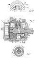
- An axial piston compressor 1 has, for example, seven pistons 2, which in Arranged circumferentially at the same angular distance from each other and in Cylinder bores 3 of a cylinder block 4 are axially movable back and forth.
- the stroke movement of the pistons 2 takes place through the engagement of a drive shaft 5 oblique annular swivel plate 6 in engagement chambers 7, the each adjoin closed cavities 8 of the pistons 2.
- Ball segments or ball segment-like sliding blocks 11 and 12 are provided, so that the swivel plate 6 slides between them as it rotates.
- the drive transmission from the drive shaft 5 to the annular swivel plate 6 takes place through a driver bolt 13 fastened in the drive shaft 5, the latter, for example spherical head in a radial bore 16 of the annular swivel disk 6 intervenes.
- the position of the driver head 15 is selected so that its Center point 17 with that of the spherical shape of the spherical segments 11, 12 matches. In addition, this center lies on a circular line that the geometric axes of the seven pistons. In this way the dead center position of the pistons 2 is precisely determined and a minimal harmful one Space guaranteed.
- the head shape of the free driver end enables the inclination of the to be changed annular swivel plate 6 by the driving head 15 a bearing body for the swiveling movement of the swash plate 6 changing the stroke width of the pistons 2 forms.
- Another requirement for pivoting the disc 6 is the displaceability a bearing axis 20 in the direction of the drive shaft 5 19 the bearing axis 20 through two coaxially on both sides of a sliding sleeve 21 supported bearing bolts 22, 23 formed, which also in radial bores 24, 25th the annular swivel plate 6 are mounted.
- the sliding sleeve 21 has this preferably on both sides bearing sleeves 26, 27, the annular space 28 between the Bridge the sliding sleeve 21 and the annular pivot axis 6.
- the limitation the displaceability of the bearing axis 20 and the maximum inclination of the Swivel plate 6 results from the driving pin 13 by this one in the Sliding sleeve 21 penetrates the elongated hole 30 provided so that the sliding sleeve 21st 30 stops at the ends of the elongated hole.
- the force for the angle adjustment the swivel plate 6 and thus for regulation of the compressor results from the Sum of the pressures acting against each other on both sides of the pistons 2, so that this force depends on the pressure in the engine room 33.
- This Pressure can provide a flow connection to an external source of pressurized gas his.
- the setting of the position of the sliding sleeve 21 and thus the stroke the piston 2 or the delivery rate of the compressor is carried out by at least one with the sliding sleeve 21 cooperating spring 34, 35.
- the Sliding sleeve 21 enclosed between two helical compression springs 34, 35, the are arranged on the drive shaft 5.
- a disadvantage of the known construction is that the contact principle described non-uniform deformation behavior between the driver and the swashplate of the swashplate running sides, which subsequently results in one leads to unfavorable running behavior of the sliding blocks on the swivel plate.
- the cylindrical bore of the swash plate in which the spherical end of the Carrier supports, it comes due to the very small residual wall thickness to a strong deformation in this area. This will change the running properties the sliding blocks on the swivel plate are impaired accordingly.
- Another swash plate engine is known from FR 2 782 126 A1 which a driver protrudes into a swivel plate. Compared to the state of the Technology according to DE 197 49 727 A1, however, is the tilt joint of the swivel plate shifted to the drive shaft. This is intended to maintain a more favorable balance of power become. Another advantage of this design is that the assigned Joint forces can be transmitted over a large area, with the result that a comparatively small one Construction is possible.
- the well-known driver / torque arm is both by the torque acted upon as well as by the support force of the swash plate in response to resulting gas forces. Both force and bending moment curves show their maximum in the area of the mount on the drive shaft. Accordingly, the Drive shaft must be dimensioned. The same naturally also applies to the dimensioning both the driver and the swivel plate, especially in the area of Location hole for the driver. The stronger dimensioning naturally leads inevitably to correspondingly higher masses and thus moments of inertia. This can adversely affect the control behavior and must be compensated. The stronger dimensioning also means that the pistons are assigned Joint arrangements are dimensioned larger or are dimensioned larger have to. This applies to the sliding blocks as well as for the sliding block in the Pistons and the pistons themselves.
- the size of the flat surface of the spherical segment-shaped sliding blocks results from the Thickness of the swivel ring and the size of the selected ball joints (ball diameter).
- the required size of the flat surface of the spherical segment-shaped sliding blocks is calculated in the design by the product (p x v), i.e. out of the product the surface pressure due to gas force and the friction speed due to compressor speed.
- Comparatively large pistons and large sliding blocks also have a negative effect on the Wall thickness in the bridge or foot area of the pistons, since it is comparatively large Bending moments work. Increased wall thicknesses in turn cause larger ones Piston masses.
- the present invention is based on the object To create compressors of the type mentioned, which without restriction Functional reliability can be built more easily.
- the support of the swivel plate in the axial direction should also be such that it essentially always takes place in the same place, i.e. at least not significantly shifted when the swivel plate changes its inclination.
- the construction should also not be a limiting (especially geometric) Have an influence on the dimensioning of the swashplate. This is especially true when the swivel plate is designed as a swivel ring.
- Imbalances should be kept to a minimum. Accordingly, it should be possible be to place the center of gravity of the component in the pivot or tilt point.
- the construction should also be such that wear-intensive point contact with the The swivel plate is supported. Accordingly, surface pressures should be reduced to a minimum, which also causes friction and hysteresis in the Have the tilting of the swivel plate reduced to a minimum.
- an essential core of the present invention is therefore that the axial Support of the piston or gas forces outside of between the piston and Swivel disc arranged joint arrangement is effective.
- the Swivel plate for this purpose preferably one between the piston and Swivel disc effective joint arrangement overlapping, on the support element adjacent support arch.
- the swivel plate is axially supported outside the hinge arrangement, i.e. outside the effective range of the aforementioned Sliding blocks.
- the support arch has the advantage that it supports the piston foot from one side, namely overlaps or encompasses radially from the inside, in any pivot position the swashplate is collision-free.
- a structural constraint for the axial Support in the area between the sliding blocks, as is the case in the prior art the case is effectively avoided by the construction according to the invention.
- this either extending through an elongated hole in the drive shaft Hinge pin or two diametrically extending relative to the drive shaft Bearing pin includes, each with its drive shaft ends with a along the drive shaft axially displaceably mounted sliding body are connected.
- the sliding body can be used as a sliding sleeve or as a hollow drive shaft be formed within the same axially displaceable sliding pin. The torque is transmitted from the drive shaft via this swivel bearing on the swashplate.
- the axial support of the swivel plate or gas force support takes place essentially only in cooperation with the support arch a support element rotating with the drive shaft, the axial support is usually additionally supported by one or more springs that is centered on the drive shaft in accordance with the prior art (Spring / return spring).
- the shaft also has two opposite slots, through which extend through the two bearing bolts. The two ends of the The aforementioned elongated holes also make stops for the maximum axial Displacement of the bearing bolts.
- the support surface of the support arch preferably extends approximately concentrically to the Center of the articulated arrangement between the piston and the swivel plate or concentric to the spherical surfaces of the joint arrangement between Piston and swivel plate defining joint blocks.
- the support arch extends over the free end face of the Piston foot with appropriate design of the pistons and connection of the same on a swivel disc or on a swivel ring.
- the pivot bearing is used Swivel plate essentially only for torque transmission and that Support element essentially only for the axial support of the pistons or Gas force support.
- the support arch can also be within a Attack recess on the support element in such a way that in addition a lateral guide is guaranteed.
- the support element also serves to transmit Torques.
- the support arch is preferably formed in one piece with the swivel plate. He can however also be firmly connected to this as a separate component, either by welding, gluing or screwing.
- the support surface of the support element is flat.
- a arcuate formation is, however, equally conceivable, especially when it comes to a displacement of the upper one due to the inclination of the swivel plate Compensate dead center of the pistons.
- the support surface of the support element can in a preferred embodiment a ball or cylinder pin segment pivotally mounted within the same be defined, the support arch then resting on the flat side of this element. Accordingly, the support surface of the support arch is then also flat.
- the advantage of this construction is that in any case a flat support is guaranteed with a correspondingly low surface pressure.
- the advantage is correct shown.
- Another major advantage is that the position of the Joint does not change. In other words, the concentricity of Sliding block arrangement and cylinder pin segment can be guaranteed. The meaning lies thereby supporting the piston forces as close as possible to the point of force application, and the constant position of the support. There is no bigger moment through that Position change.
- the aforementioned support arch has a relative shape in the case of an arch-shaped support surface has a large diameter, is also almost flat in this construction Support given.
- the support is along a line. In practice, this line spreads under pressure with a narrow strip the consequence that the specific surface pressure is relatively low.
- the support arch can be on the support surface of the support element by a retaining pin or Retaining bracket to be held in the system. This will lift the support arch from the Support surface of the support element effectively prevented.
- FIG. 1-8 is a first embodiment of an inventive Swing plate mechanism 100 for an axial piston compressor for automotive air conditioning systems shown schematically.
- This swivel plate mechanism 100 comprises an adjustable in its inclination to a drive shaft 104, of which Drive shaft rotatably driven, in the present case annular swivel plate 107, these both with an axially displaceably mounted on the drive shaft 104 Sliding sleeve 108 and with a distance from the drive shaft 104 with this pivoting support element 109 is pivotally connected.
- This articulated Connection is designed as an axial support, such as in particular FIGS. 2, 4 and 5 up to 8.
- the interaction of the swivel ring 107 with the axial piston corresponds to that according to the prior art, for example according to FIG. 18.
- the pivot bearing of the pivot ring 107 defines itself transversely to the drive shaft 104 extending pivot axis 101.
- This pivot axis 101 is further defined by two bearing pins mounted on both sides of the sliding sleeve 108 on the same axis 102, 103.
- These bearing bolts 102, 103 are in radial bores of the Swivel ring 107 mounted.
- the sliding sleeve can be used on both sides for this purpose additionally have bearing sleeves 105, 106 (see also FIGS. 15 and 16) which bridge the annular space between the sliding sleeve 108 and the swivel ring 107.
- the corresponding construction largely corresponds to the state of the art corresponding to FIGS. 18 and 19.
- This support takes place by a arranged on the swivel ring 107, in particular integrally with this support arch 110.
- This support arch 110 is in accordance with FIG. 9 designed so that it is the effective joint arrangement between the piston and the swivel ring overlaps, and in such a way that regardless of the inclination of the Swivel ring 107 a collision between this and the support arch 110 on the one hand and the piston foot 111 comprising the aforementioned joint arrangement (FIG. 9) on the other hand is excluded.
- the support element 109 is an integral part of a with the drive shaft 104 rotating disc 112, namely a raised opposite the disc formed circle segment (see in particular FIGS. 9 and 10).
- the support surface of the arch 110 extends approximately concentrically to the center the joint arrangement effective between the piston and the swivel disk or swivel ring 107, as described in more detail with reference to FIG. 18.
- the axial support is therefore effective outside of the aforementioned joint arrangement, with the result that the hinge arrangement between the piston and swivel plate or swivel ring is effective, is not affected by axial support measures. This applies in particular for the dimensioning of the aforementioned joint arrangement.
- the pivot bearing the swivel plate or swivel ring 107 only for torque transmission and the support element 109 only for the axial support of the pistons or gas force support serve.
- the torque transmission is therefore from the axial support of the swivel ring 107 decoupled.
- the swivel ring 107 is in an inclined position for maximum piston stroke.
- 3, 4, 7 and 8 show the swivel ring 107 in one Minimum piston stroke position.
- FIGS. 6 and 8 in continuation of the supporting surface of the Supporting arch 110 shows that the supporting surface of the supporting arch 110 is an arc describes. This can be deliberately deviated from if necessary to a predetermined "Offset" of the support of the support arch 109 from the piston longitudinal axis to compensate for changes in the inclination of the swivel ring 107.
- the support arch 110 can either be an integral component of the swivel ring 107 or according to FIGS. 5-8 as a separate component with the swivel ring 107 be rigidly connected.
- the latter embodiment has the advantage that the swivel ring grinds precisely on both flat sides, resulting in one correspondingly high parallelism of the two opposite treads for the sliding blocks mentioned at the beginning.
- the support arch 110 extends this preferably into a corresponding depression 113 on the support arch 110 facing side of the support member 109 into it (see FIGS. 9 and 10).
- the trough 113 is preferably designed as a radial groove.
- this embodiment is characterized in that the pivot bearing of the swivel ring 107 by two diametrically on the sliding sleeve 108 molded spokes 117 is formed, the end faces of which are spherical. These spherical end faces correspond to complementary spherical ones Troughs on the radially inner side of the swivel ring 107 such that a Swing axis 101 for swivel ring 107 extending transversely to drive shaft 104 is defined relative to the sliding sleeve 108 and drive shaft 104.
- the maximum tilt angle of the swivel ring 107 is approximately 18 °, during the minimum tilt angle is between about 0 ° and 2 °.
- the tilt angle can be through Stops can be specified, in particular stops for the axial displacement of the Sliding sleeve 108.
- the support arch extends approximately concentrically to the center effective joint arrangement between piston and swivel plate.
- the axial support or (theoretically) support line on the center of the circular sliding blocks in projection lie. This center point coincides with the longitudinal axis of the piston.
- the contact surface between the support arch 110 and the support element 109 moves from a minimum tilt position into a maximum tilt position from a central position Z 1 , which lies on the longitudinal axis of the piston, to a position when the swivel plate or swivel ring 107 is inclined Z 2 .
- this lateral offset amounts to approximately 1.8 mm, provided the swivel disk or the swivel ring is swiveled by approximately 20 ° from a position of 90 ° to the drive shaft 104.
- the swivel bearing of the swivel disk or swivel ring 107 moves from a position L to a position L 'along the drive shaft 104.
- This "zero position" of the support area can therefore be provided as desired, for example also in such a way that the aforementioned offset when the swivel plate is inclined or the swivel ring is compensated, especially if the swivel plate or the swivel ring 107 moves from the minimum position to the maximum inclination position emotional. It is also conceivable to use the “zero position” mentioned for a medium tilt angle to provide the swivel ring 107.
- the gas force curve is over the angle of rotation of the drive shaft 104 specified. It is only a qualitative view.
- Fig. 12 left seven pistons or cylinders of an axial piston compressor are indicated. The top dead center of the pistons is in Fig. 12 between the pistons 4 and 5.
- Im the pistons 3, 4 and 5 essentially determine by axial force and tilting moment the tilting behavior of the swivel plate or the swivel ring 107, while the Pistons 1, 2, 6 and 7 are not particularly relevant in this regard.
- the contact surface should preferably lie exactly in the geometric TDC.
- the support arch 110 extends in the illustrated exemplary embodiments from radially inside out. However, it is just as well a reverse extension conceivable. It is crucial in both cases that the support surface of the support arch is approximately circular arc-shaped to the above-described constellation of Obtain axial support.
- FIG. 13 shows an embodiment variant for the support of the swivel ring 107 on the support element 109 in a schematic section and on an enlarged scale.
- This embodiment is distinguished from the above-described embodiment in that the support surface of the support element 109 is defined by a cylindrical pin segment 118 which is pivotably mounted therein and on the flat side 119 of which the support arch 110 bears.
- the support arch 110 is not designed in the form of a circular arc, but rather approximately U-shaped.
- the leg facing the support surface of the support element 109 is formed with a flat sliding surface which rests on the flat side 119 of the cylindrical pin segment 118.
- the support arch 110 can be attached to the Support surface of the support member 109 by a holding pin or bracket 120 or the like. Holding means are held in order to lift the support arch 110 from the Prevent support surface of the support member 109. In this case it is natural expedient, too. the contour of the swivel ring 107 facing Support arch 110 to form a circular arc.
- the basic idea according to the invention is for axial Supporting a swivel plate also includes constructions in which the support arch inside, outside or from above (tensile force instead of compressive force), where Common to all constructions is that the support arch or the axial Support of the swivel ring or the swivel plate concentrically outside of Articulated stones or the effective area of the articulated stones is arranged and effective.
- This design not only has the advantage that the articulated stone arrangement is optimal can be dimensioned, but also the advantage of a contact surface between a plane and a circular arc with a relatively large diameter, resulting in a rather flat strip-like, i.e. flat support is achieved.
- 14a and 14b is a variant of a swivel ring mechanism shown, in which the support arch 110 is attached radially on the outside to the support ring 107.
- the support principle like it 1 ff., changes in this embodiment according to 14a, 14b not.
Landscapes
- Engineering & Computer Science (AREA)
- Mechanical Engineering (AREA)
- General Engineering & Computer Science (AREA)
- Compressors, Vaccum Pumps And Other Relevant Systems (AREA)
Applications Claiming Priority (2)
| Application Number | Priority Date | Filing Date | Title |
|---|---|---|---|
| DE2003124802 DE10324802A1 (de) | 2003-06-02 | 2003-06-02 | Axialkolbenverdichter, insbesondere CO2-Verdichter für Kraftfahrzeug-Klimaanlagen |
| DE10324802 | 2003-06-02 |
Publications (1)
| Publication Number | Publication Date |
|---|---|
| EP1484503A2 true EP1484503A2 (fr) | 2004-12-08 |
Family
ID=33154514
Family Applications (1)
| Application Number | Title | Priority Date | Filing Date |
|---|---|---|---|
| EP20040012111 Withdrawn EP1484503A2 (fr) | 2003-06-02 | 2004-05-21 | Compresseur à plateau en biais utilisant du CO2 comme fluide frigorigène |
Country Status (2)
| Country | Link |
|---|---|
| EP (1) | EP1484503A2 (fr) |
| DE (1) | DE10324802A1 (fr) |
Cited By (1)
| Publication number | Priority date | Publication date | Assignee | Title |
|---|---|---|---|---|
| CN115949565A (zh) * | 2022-12-01 | 2023-04-11 | 新乡航空工业(集团)有限公司 | 一种力平衡斜盘配流的柱塞泵 |
Family Cites Families (8)
| Publication number | Priority date | Publication date | Assignee | Title |
|---|---|---|---|---|
| JPH05312144A (ja) * | 1992-05-08 | 1993-11-22 | Sanden Corp | 可変容量斜板式圧縮機 |
| JP3125952B2 (ja) * | 1993-04-08 | 2001-01-22 | 株式会社豊田自動織機製作所 | 容量可変型斜板式圧縮機 |
| JP3422186B2 (ja) * | 1995-11-24 | 2003-06-30 | 株式会社豊田自動織機 | 可変容量圧縮機 |
| DE19749727C2 (de) * | 1997-11-11 | 2001-03-08 | Obrist Engineering Gmbh Lusten | Hubkolbenmaschine mit Schwenkscheibengetriebe |
| FR2782126B1 (fr) * | 1998-08-10 | 2000-10-13 | Valeo Climatisation | Compresseur a cylindree variable |
| JP2001304102A (ja) * | 2000-04-18 | 2001-10-31 | Toyota Industries Corp | 可変容量圧縮機 |
| JP2002031043A (ja) * | 2000-07-14 | 2002-01-31 | Toyota Industries Corp | 圧縮機 |
| JP4838485B2 (ja) * | 2000-11-10 | 2011-12-14 | ルーク ファールツォイク・ヒドラウリク ゲゼルシャフト ミット ベシュレンクテル ハフツング ウント コンパニー コマンディートゲゼルシャフト | 往復動ピストン機械 |
-
2003
- 2003-06-02 DE DE2003124802 patent/DE10324802A1/de not_active Withdrawn
-
2004
- 2004-05-21 EP EP20040012111 patent/EP1484503A2/fr not_active Withdrawn
Cited By (1)
| Publication number | Priority date | Publication date | Assignee | Title |
|---|---|---|---|---|
| CN115949565A (zh) * | 2022-12-01 | 2023-04-11 | 新乡航空工业(集团)有限公司 | 一种力平衡斜盘配流的柱塞泵 |
Also Published As
| Publication number | Publication date |
|---|---|
| DE10324802A1 (de) | 2004-12-30 |
Similar Documents
| Publication | Publication Date | Title |
|---|---|---|
| EP0964997B1 (fr) | Moteur a pistons avec entrainement par disque de verrouillage | |
| EP1573200A1 (fr) | Machine a piston axiaux | |
| EP1607630B1 (fr) | Compresseur à piston | |
| DE4311432C2 (de) | Taumelscheibenkompressor mit variabler Förderleistung | |
| EP0752530B1 (fr) | Machine à piston alternatif et entraínement par plateau oscillant | |
| DE10315477B4 (de) | Axialkolbenverdichter, insbesondere CO2-Verdichter für Kraftfahrzeug-Klimaanlagen | |
| EP1872013B1 (fr) | Compresseur a pistons axiaux | |
| EP1844234B1 (fr) | Compresseur a pistons axiaux | |
| DE10152097B4 (de) | Verstellbarer Taumelscheibenkompressor | |
| EP1484503A2 (fr) | Compresseur à plateau en biais utilisant du CO2 comme fluide frigorigène | |
| DE10358728B4 (de) | Axialkolbenmaschine zum unabhängigen Fördern in mehrere hydraulische Kreisläufe | |
| DE10010132C2 (de) | Hubkolbenmaschine | |
| DE19515658C2 (de) | Taumelscheibenkompressor mit schwenkbarer Taumelscheibe | |
| EP1649165B1 (fr) | Compresseur a piston axial, notamment compresseur co2 pour systemes de climatisation de vehicules | |
| EP1781947A1 (fr) | Compresseur a pistons axiaux | |
| DE102005039199A1 (de) | Axialkolbenverdichter | |
| EP1636492B1 (fr) | Compresseur a piston axial, notamment compresseur pour installation de climatisation d'automobile | |
| DE102006040490A1 (de) | Axialkolbenverdichter | |
| WO2001065071A2 (fr) | Machine a pistons alternatifs | |
| EP1602829A2 (fr) | Compresseur à plateau en biais | |
| DE10065313A1 (de) | Axialkolbenmaschine mit verstellbarem Hubvolumen und von Biegemomenten befreiter Antriebswelle | |
| DE102005033706A1 (de) | Axialkolbenverdichter |
Legal Events
| Date | Code | Title | Description |
|---|---|---|---|
| PUAI | Public reference made under article 153(3) epc to a published international application that has entered the european phase |
Free format text: ORIGINAL CODE: 0009012 |
|
| AK | Designated contracting states |
Kind code of ref document: A2 Designated state(s): AT BE BG CH CY CZ DE DK EE ES FI FR GB GR HU IE IT LI LU MC NL PL PT RO SE SI SK TR |
|
| AX | Request for extension of the european patent |
Extension state: AL HR LT LV MK |
|
| RAP1 | Party data changed (applicant data changed or rights of an application transferred) |
Owner name: VALEO COMPRESSOR EUROPE GMBH |
|
| STAA | Information on the status of an ep patent application or granted ep patent |
Free format text: STATUS: THE APPLICATION IS DEEMED TO BE WITHDRAWN |
|
| 18D | Application deemed to be withdrawn |
Effective date: 20091201 |