EP1484523B1 - Elément d'accouplement centrifuge à réponse thermique - Google Patents
Elément d'accouplement centrifuge à réponse thermique Download PDFInfo
- Publication number
- EP1484523B1 EP1484523B1 EP03450140A EP03450140A EP1484523B1 EP 1484523 B1 EP1484523 B1 EP 1484523B1 EP 03450140 A EP03450140 A EP 03450140A EP 03450140 A EP03450140 A EP 03450140A EP 1484523 B1 EP1484523 B1 EP 1484523B1
- Authority
- EP
- European Patent Office
- Prior art keywords
- clutch
- clutch element
- disk
- drive shaft
- driven
- Prior art date
- Legal status (The legal status is an assumption and is not a legal conclusion. Google has not performed a legal analysis and makes no representation as to the accuracy of the status listed.)
- Expired - Lifetime
Links
- 230000008878 coupling Effects 0.000 title description 55
- 238000010168 coupling process Methods 0.000 title description 55
- 238000005859 coupling reaction Methods 0.000 title description 55
- XLYOFNOQVPJJNP-UHFFFAOYSA-N water Substances O XLYOFNOQVPJJNP-UHFFFAOYSA-N 0.000 claims description 17
- 239000000463 material Substances 0.000 claims description 14
- 229920001971 elastomer Polymers 0.000 claims description 11
- 239000000806 elastomer Substances 0.000 claims description 7
- 229910000906 Bronze Inorganic materials 0.000 claims description 3
- 239000010974 bronze Substances 0.000 claims description 3
- KUNSUQLRTQLHQQ-UHFFFAOYSA-N copper tin Chemical compound [Cu].[Sn] KUNSUQLRTQLHQQ-UHFFFAOYSA-N 0.000 claims description 3
- NIXOWILDQLNWCW-UHFFFAOYSA-M Acrylate Chemical compound [O-]C(=O)C=C NIXOWILDQLNWCW-UHFFFAOYSA-M 0.000 claims description 2
- 239000007769 metal material Substances 0.000 claims description 2
- 239000012815 thermoplastic material Substances 0.000 claims description 2
- 229920001195 polyisoprene Polymers 0.000 claims 4
- RRHGJUQNOFWUDK-UHFFFAOYSA-N Isoprene Chemical compound CC(=C)C=C RRHGJUQNOFWUDK-UHFFFAOYSA-N 0.000 claims 3
- NTXGQCSETZTARF-UHFFFAOYSA-N buta-1,3-diene;prop-2-enenitrile Chemical compound C=CC=C.C=CC#N NTXGQCSETZTARF-UHFFFAOYSA-N 0.000 claims 1
- -1 ethylenepropylene caoutchouc Chemical compound 0.000 claims 1
- 238000007373 indentation Methods 0.000 claims 1
- 229920001296 polysiloxane Polymers 0.000 claims 1
- 230000000694 effects Effects 0.000 description 5
- 239000002184 metal Substances 0.000 description 5
- 229910052751 metal Inorganic materials 0.000 description 5
- 230000035945 sensitivity Effects 0.000 description 5
- 230000001419 dependent effect Effects 0.000 description 4
- 230000013011 mating Effects 0.000 description 4
- 239000005060 rubber Substances 0.000 description 4
- 238000002485 combustion reaction Methods 0.000 description 3
- 150000002739 metals Chemical class 0.000 description 3
- 230000011218 segmentation Effects 0.000 description 3
- 229920001169 thermoplastic Polymers 0.000 description 3
- 230000009471 action Effects 0.000 description 2
- 239000007788 liquid Substances 0.000 description 2
- 238000004519 manufacturing process Methods 0.000 description 2
- 239000002245 particle Substances 0.000 description 2
- 238000005507 spraying Methods 0.000 description 2
- 239000004416 thermosoftening plastic Substances 0.000 description 2
- 229920000181 Ethylene propylene rubber Polymers 0.000 description 1
- 229920000459 Nitrile rubber Polymers 0.000 description 1
- 238000005299 abrasion Methods 0.000 description 1
- 238000010521 absorption reaction Methods 0.000 description 1
- 230000008901 benefit Effects 0.000 description 1
- 230000015572 biosynthetic process Effects 0.000 description 1
- 230000008859 change Effects 0.000 description 1
- 239000002826 coolant Substances 0.000 description 1
- 238000001816 cooling Methods 0.000 description 1
- 238000005260 corrosion Methods 0.000 description 1
- 230000007797 corrosion Effects 0.000 description 1
- 229920001973 fluoroelastomer Polymers 0.000 description 1
- 239000000446 fuel Substances 0.000 description 1
- 238000010438 heat treatment Methods 0.000 description 1
- 238000012423 maintenance Methods 0.000 description 1
- 229920002379 silicone rubber Polymers 0.000 description 1
- 239000004945 silicone rubber Substances 0.000 description 1
- 238000004073 vulcanization Methods 0.000 description 1
Images
Classifications
-
- F—MECHANICAL ENGINEERING; LIGHTING; HEATING; WEAPONS; BLASTING
- F16—ENGINEERING ELEMENTS AND UNITS; GENERAL MEASURES FOR PRODUCING AND MAINTAINING EFFECTIVE FUNCTIONING OF MACHINES OR INSTALLATIONS; THERMAL INSULATION IN GENERAL
- F16D—COUPLINGS FOR TRANSMITTING ROTATION; CLUTCHES; BRAKES
- F16D43/00—Automatic clutches
- F16D43/02—Automatic clutches actuated entirely mechanically
- F16D43/04—Automatic clutches actuated entirely mechanically controlled by angular speed
- F16D43/14—Automatic clutches actuated entirely mechanically controlled by angular speed with centrifugal masses actuating the clutching members directly in a direction which has at least a radial component; with centrifugal masses themselves being the clutching members
-
- F—MECHANICAL ENGINEERING; LIGHTING; HEATING; WEAPONS; BLASTING
- F16—ENGINEERING ELEMENTS AND UNITS; GENERAL MEASURES FOR PRODUCING AND MAINTAINING EFFECTIVE FUNCTIONING OF MACHINES OR INSTALLATIONS; THERMAL INSULATION IN GENERAL
- F16D—COUPLINGS FOR TRANSMITTING ROTATION; CLUTCHES; BRAKES
- F16D43/00—Automatic clutches
- F16D43/02—Automatic clutches actuated entirely mechanically
- F16D43/25—Automatic clutches actuated entirely mechanically controlled by thermo-responsive elements
Definitions
- the invention relates to a coupling element for a driven via a drive shaft unit, in particular for a water pump, wherein the coupling element has a fixedly connected to the drive shaft temperature and / or speed-sensitive coupling member which acts temperature and / or speed dependent on a driven part of the unit , wherein the coupling member is formed by a coupling disc whose outer surface forms at least a first coupling surface for non-positive connection with a corresponding, formed by an inner circumferential surface of the driven part counter surface.
- a water pump with a main wheel and a slave wheel wherein main and Maulaufrad are arranged coaxially with respect to a drive shaft.
- the main wheel is rigidly connected to a drive shaft
- the slave wheel is rotatably mounted on the main wheel, wherein between the main wheel and the slave wheel, a temperature-sensitive coupling part is arranged.
- a rotary connection between the slave wheel and the main wheel is made, so that the slave wheel is driven with the main wheel.
- the capacity of the water pump of the required cooling capacity can be adjusted.
- the water pump has a relatively high production cost.
- a thermally engaging centrifugal clutch is known.
- the clutch has a speed-sensitive ring, which causes a sliding between the coupling parts from a predetermined drive shaft speed in order not to exceed a predetermined maximum drive speed for an aggregate.
- US 3,105,580 A shows a thermostatically controlled clutch having a thermally sensitive element for operating a fan above a predetermined temperature.
- the temperature-sensitive element is designed as a bimetal, which presses a coupling band frictionally against a coupling surface of a clutch drum from a predetermined temperature.
- the coupling has the disadvantage that it is poorly suited for units subject to corrosion, such as water pumps.
- a thermostatically controlled fan which is driven via a clutch disc by a belt drive.
- the coupling device has a thermostatic element, which causes a spring part depending on the temperature stronger or weaker act on the clutch disc, so that at low temperature of the fan under sliding friction of the clutch disc, that is, with formation of a certain slip relative to the drive shaft driven.
- the fan is non-positively connected to the drive shaft and runs synchronously with this.
- this coupling device has the disadvantage that a relatively large amount of space is claimed.
- a coupling device for a radiator fan having a temperature-sensitive element with a temperature-expanding material, such as wax or rubber.
- GB 720 168 A discloses a centrifugal clutch with a number of spaced-apart coupling blocks, which are pressed under the influence of centrifugal force to the outside and thus pressed against a clutch drum.
- the coupling blocks are driven by an annular coupling element, which are connected to the coupling blocks via an annular rubber body.
- GB 938 532 A shows a further centrifugal clutch in which a disc-shaped coupling body is pressed under centrifugal force outwards against a clutch drum, wherein the rubber body is also pressed by a star-shaped drive element to the outside.
- Further centrifugal clutches are known from EP 0 363 013 A1 and US 4,889,215 A, wherein coupling elements are pressed elastically outwards against a clutch drum.
- centrifugal and thermal coupling elements are designed as dry clutches and are not suitable for wet use, such as for driving a water pump, the coupling surfaces are at least occasionally acted upon by a liquid such as water. Clutches designed for dry use would fail when wet, because forms a bearing liquid film between the coupling surfaces and thus causes an effect known as "aquaplaning".
- the object of the invention is to develop a temperature-sensitive coupling element, which is to produce with the least possible effort and takes up little space.
- the coupling element should be low-maintenance and as insensitive as possible to corrosive media.
- the first and / or second coupling surface has at least one drainage groove. Drainage grooves of this type are particularly advantageous when the coupling element is used for water pumps. As a result, a so-called “aquaplaning effect" can be avoided. Furthermore, the drainage grooves on the coupling surface serve for receiving and removing possible particles in the water cycle.
- the clutch disc It is essential that a material is chosen for the clutch disc, which undergoes the largest possible volume change in temperature differences in the desired operating range.
- the material of the clutch disc has a higher coefficient of thermal expansion than the drive shaft and / or the part to be driven.
- the driven part - for example, the impeller of a water pump - is advantageously rotatably mounted on the drive shaft and is decoupled below a predefined minimum speed of the drive shaft and below a predefined minimum temperature of the drive shaft.
- the clutch disc In the cold state and in the low speed range, the clutch disc has a precisely defined gap between the clutch face of the clutch disc and a corresponding mating face of the driven part.
- Exceeds the temperature of the clutch disc and / or the rotational speed of the drive shaft has a predefined minimum value, then there is a coupling of the coupling element. An increase in temperature causes expansion and thus engagement of the clutch disc.
- the sensitivity between thermal and speed sensitivity can be varied.
- a purely thermally dependent coupling function can be achieved for example by thermoplastic or metallic material for the clutch disc. In the latter case, it is also possible to use a sintered metal, for example sintered bronze.
- a speed dependency can be achieved particularly well when the clutch disc, at least partially, of an elastomer, preferably of acrylonitrile-butadiene rubber, acrylate rubber, ethylene-propylene rubber, silicone rubber, fluororubber or the like consists.
- An increase in the temperature of the clutch disc causes expansion of the material and thus engagement of the clutch disc. Is this made of elastomer, the material is softened by the temperature and ensures easy stretching by the centrifugal force and earlier entrainment of the driven part.
- the coupling surface is formed wear-resistant.
- a wear-resistant surface can be achieved by spraying or vulcanizing the coupling surface.
- An increase in the rotational speed sensitivity of the clutch disk can be achieved if the clutch disk is segmented in the circumferential direction, wherein it is preferably provided that the segmentation is formed by cuts extending from the clutch surface, preferably radially or spirally, into an inner region of the clutch disk.
- the segmentation causes the individual radial segments of the clutch disc to be pressed radially enough outward under the action of centrifugal force even at relatively low rotational speeds, and to cause the clutch disc to engage the driven part.
- drive shaft and clutch disc are positively connected with each other.
- a safe drive of the clutch disc is achieved.
- a first end face of the clutch disc forms a second coupling surface for non-positive connection with a corresponding, formed by an end face of the part to be driven second mating surface is particularly advantageous. This allows a particularly good torque ratio.
- a support disc fixedly connected to the drive shaft is arranged in the region of at least one end face of the clutch disc. The support disc prevents the clutch disc from dodging in the axial direction and a bumping of the clutch disc occurs.
- the clutch disc is made of an elastomer, then a Shore hardness of between 60 and 70 has proven to be advantageous.
- the coupling element according to the invention consists of very few individual parts and requires extremely little space. This makes it possible that the coupling element is disposed within a housing of the unit, in particular within a water pump housing.
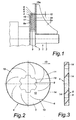
- a unit 1 formed by a water pump in the exemplary embodiment is driven by a drive shaft 2 via a coupling element 3.
- the coupling element 3 has a temperature and / or speed-dependent coupling member 4, which is positively connected to the drive shaft 2.
- the coupling member 4 is formed by a clutch disc 5, whose outer circumferential surface forms a first coupling surface 6.
- the exemplary embodiment formed by an impeller to be driven part 7 has a corresponding first mating surface 8, on which the first coupling surface 6 acts in the engaged state.
- the positive connection 9 between the clutch disc 5 and drive shaft 2 can be achieved by a toothing or a corresponding profiling of the hub 16, as is apparent in particular from FIG.
- the material for the clutch disc 5 As the material for the clutch disc 5, a material with the highest possible coefficient of thermal expansion in the desired temperature range - for example, between -40 ° C and 150 ° C - is selected.
- Clutch discs 5 made of thermoplastics and metals are suitable for purely thermal functions. Clutch discs made of metals are abrasion resistant and therefore highly durable. Also, sintered metal, for example sintered bronze, can be used.
- Clutch discs 5 made of elastomers are suitable if both a thermally and speed-dependent clutch function is desired.
- the adhesion is carried out both by thermal expansion and centrifugal expansion of the clutch disc 5.
- the first clutch surface 6 may be performed wear-resistant, for example by spraying or by vulcanization of a wear-resistant material.
- a second coupling surface 6a may also be arranged in the region of a first end face 18 of the clutch disk 5, which in the engaged state cooperates with a second counter surface 8a formed by an end face of the part 7 to be driven.
- the first coupling surface 6 and / or the second coupling surface 6a and / or the corresponding mating surfaces 8, 8a are provided with drainage grooves 14 which, in particular when used for a water pump, have a so-called "aquaplaning effect". avoid and also serve the absorption and removal of possible particles in the water cycle.
- the clutch disc 5 must in the cold state and in the low speed range in each case with a precisely defined gap 15, 15a between the clutch surfaces 6, 6a of the clutch disc 5 and the corresponding counter surfaces 8, 8a of the part 7 run. If the temperature and / or the rotational speed increase above the minimum value, the coupling element 3 is engaged.
- the use of the coupling element 3 in a water pump of an internal combustion engine has the advantage that the operating temperature of the engine can be reached quickly and causes a corresponding fuel economy. Since the impeller stands still in the warm-up phase or rotates slowly as a result of hydrodynamic effects in the gap 15, 15a, the cold cycle of the coolant system of the internal combustion engine can be heated up more quickly. This has the effect that the operating temperature of the internal combustion engine is reached earlier and the full heating power is available at an early stage.
Landscapes
- Engineering & Computer Science (AREA)
- General Engineering & Computer Science (AREA)
- Mechanical Engineering (AREA)
- Structures Of Non-Positive Displacement Pumps (AREA)
- Hydraulic Clutches, Magnetic Clutches, Fluid Clutches, And Fluid Joints (AREA)
- Centrifugal Separators (AREA)
- Mechanical Operated Clutches (AREA)
- Reciprocating Pumps (AREA)
- Braking Arrangements (AREA)
- One-Way And Automatic Clutches, And Combinations Of Different Clutches (AREA)
Claims (15)
- Elément d'embrayage (3) pour une unité (1) entraînée par un arbre d'entraînement (2), notamment une pompe à eau, cet élément d'embrayage (3) ayant un organe d'embrayage (4) solidaire de l'arbre d'entraînement (2) et sensible à la température et/ou à la vitesse de rotation, et cet organe d'embrayage agit en fonction de la température et/ou de la vitesse de rotation sur une partie (7) à entraîner de l'unité (1),
l'organe d'embrayage (4) étant formé par un disque d'embrayage (5) dont la surface enveloppe extérieure forme au moins une première surface d'embrayage (6) pour être reliée par une liaison de force à une contre surface (8) correspondante, formée par la surface enveloppe intérieure de la pièce (7) à entraîner,
caractérisé en ce que
la première et/ou la seconde surface d'embrayage (6, 6a) ont au moins une rainure de drainage (14). - Elément d'embrayage (3) selon la revendication 1,
caractérisé en ce que
une première surface frontale (18) du disque d'embrayage (5) forme une seconde surface d'embrayage (6a) pour une liaison par la force avec une seconde contre surface (8b) correspondante, formée par une surface frontale de la pièce à entraîner. - Elément d'embrayage (3) selon l'une quelconque des revendications 1 ou 2,
caractérisé en ce que
la matière du disque d'embrayage (5) a un coefficient de dilatation thermique plus élevé que celui de l'arbre d'entraînement (2) et/ou de la pièce (7) à entraîner. - Elément d'embrayage (3) selon l'une quelconque des revendications 1 à 3,
caractérisé en ce que
le disque d'embrayage (5) est formé au moins en partie d'un élastomère de préférence en caoutchouc acrylnitril-butadiène, en caoutchouc d'acrylate, en caoutchouc éthylène-propylène, en caoutchouc au silicone, en caoutchouc au fluor ou analogue. - Elément d'embrayage (3) selon la revendication 4,
caractérisé en ce que
la matière du disque d'embrayage (5) a une dureté Shore comprise entre environ 60 et 70. - Elément d'embrayage (3) selon l'une quelconque des revendications 1 à 5,
caractérisé en ce que
le disque d'embrayage (5) est au moins en partie réalisé en une matière thermoplastique. - Elément d'embrayage (3) selon l'une quelconque des revendications 1 à 6,
caractérisé en ce que
le disque d'embrayage (5) est réalisé au moins en partie en une matière métallique. - Elément d'embrayage (3) selon la revendication 7,
caractérisé en ce que
le disque d'embrayage (5) est au moins en partie en un métal fritté, de préférence en bronze fritté. - Elément d'embrayage (3) selon l'une quelconque des revendications 1 à 8,
caractérisé en ce que
la première et/ou la seconde surface d'embrayage (6) sont résistantes à l'usure. - Elément d'embrayage (3) selon l'une quelconque des revendications 1 à 9,
caractérisé en ce que
le disque d'embrayage (5) est segmenté dans sa direction périphérique. - Elément d'embrayage (3) selon la revendication 10,
caractérisé en ce que
la segmentation est formée par des entailles (10) de préférence radiales ou en spirales partant de la première surface d'embrayage (6), pour rejoindre une zone intérieure (12) du disque d'embrayage (5). - Elément d'embrayage (3) selon l'une quelconque des revendications 1 à 11,
caractérisé en ce que
l'arbre d'entraînement (2) et le disque d'embrayage (5) sont reliés par une liaison de forme. - Elément d'embrayage (3) selon l'une quelconque des revendications 1 à 12,
caractérisé en ce qu'
au niveau d'au moins une seconde surface frontale (19) du disque d'embrayage (5), un disque d'appui (17) est relié solidairement à l'arbre d'entraînement (2). - Elément d'embrayage (3) selon l'une quelconque des revendications 1 à 13,
caractérisé en ce que
la partie (7) à entraîner est montée en rotation sur l'arbre d'entraînement (2). - Elément d'embrayage (3) selon l'une quelconque des revendications 1 à 14,
caractérisé en ce qu'
il est logé dans un boîtier de l'unité (1), notamment dans le corps d'une pompe à eau.
Priority Applications (7)
| Application Number | Priority Date | Filing Date | Title |
|---|---|---|---|
| EP03450140A EP1484523B1 (fr) | 2003-06-02 | 2003-06-02 | Elément d'accouplement centrifuge à réponse thermique |
| ES03450140T ES2245440T3 (es) | 2003-06-02 | 2003-06-02 | Elemento de acoplamiento de fuerza centrifuga sensible al calor. |
| DE50301231T DE50301231D1 (de) | 2003-06-02 | 2003-06-02 | Wärmeempfindliches Fliehkraftkupplungselement |
| AT03450140T ATE305097T1 (de) | 2003-06-02 | 2003-06-02 | Wärmeempfindliches fliehkraftkupplungselement |
| SI200330067T SI1484523T1 (sl) | 2003-06-02 | 2003-06-02 | Na toploto obcutljiv centrifugalni sklopilni element |
| US10/817,946 US6994197B2 (en) | 2003-06-02 | 2004-04-06 | Clutch element for a unit driven via a drive shaft |
| JP2004158930A JP2004360909A (ja) | 2003-06-02 | 2004-05-28 | 駆動軸を介して駆動される装置のためのクラッチ |
Applications Claiming Priority (1)
| Application Number | Priority Date | Filing Date | Title |
|---|---|---|---|
| EP03450140A EP1484523B1 (fr) | 2003-06-02 | 2003-06-02 | Elément d'accouplement centrifuge à réponse thermique |
Publications (2)
| Publication Number | Publication Date |
|---|---|
| EP1484523A1 EP1484523A1 (fr) | 2004-12-08 |
| EP1484523B1 true EP1484523B1 (fr) | 2005-09-21 |
Family
ID=33155305
Family Applications (1)
| Application Number | Title | Priority Date | Filing Date |
|---|---|---|---|
| EP03450140A Expired - Lifetime EP1484523B1 (fr) | 2003-06-02 | 2003-06-02 | Elément d'accouplement centrifuge à réponse thermique |
Country Status (7)
| Country | Link |
|---|---|
| US (1) | US6994197B2 (fr) |
| EP (1) | EP1484523B1 (fr) |
| JP (1) | JP2004360909A (fr) |
| AT (1) | ATE305097T1 (fr) |
| DE (1) | DE50301231D1 (fr) |
| ES (1) | ES2245440T3 (fr) |
| SI (1) | SI1484523T1 (fr) |
Families Citing this family (5)
| Publication number | Priority date | Publication date | Assignee | Title |
|---|---|---|---|---|
| DE102006011119B4 (de) * | 2006-03-08 | 2016-05-25 | Karl Heinz Linnig Gmbh & Co. Kg | Kupplungsanordnung mit Wärmeausdehnungskupplung |
| DE102006048482A1 (de) * | 2006-10-11 | 2008-04-17 | Behr Gmbh & Co. Kg | Koppelungsvorrichtung für eine Kühlmittelpumpe, Verfahren zum Koppeln, Pumpe zum Kühlmittelpumpen |
| US20100236890A1 (en) * | 2009-02-20 | 2010-09-23 | Dave Hampson | Mechanical Clutch Having Polymer Engagement |
| US10487837B2 (en) * | 2015-01-22 | 2019-11-26 | Litens Automotive Partnership | Multi-stage impeller assembly for pump |
| JP7386054B2 (ja) * | 2019-11-13 | 2023-11-24 | 株式会社エクセディ | クラッチディスク及びトルクリミッタ |
Family Cites Families (17)
| Publication number | Priority date | Publication date | Assignee | Title |
|---|---|---|---|---|
| US2019153A (en) * | 1931-02-04 | 1935-10-29 | Continental Motors Corp | Clutch mechanism |
| US2655015A (en) | 1947-01-30 | 1953-10-13 | Linder Francois | Thermally releasable torque limiting clutch |
| GB720168A (en) * | 1950-05-16 | 1954-12-15 | Eickhoff Geb | Improvements in or relating to centrifugal clutches |
| US2987158A (en) * | 1953-09-14 | 1961-06-06 | Elmer C Kiekhaefer | Centrifugal clutch |
| US2840315A (en) | 1955-03-16 | 1958-06-24 | Thompson Prod Inc | Thermostatically controlled fan |
| US3105580A (en) | 1959-12-31 | 1963-10-01 | Borg Warner | Thermostatically controlled clutch |
| GB938532A (en) * | 1962-03-03 | 1963-10-02 | Meccanica Garelli S P A | Centrifugal clutch |
| DE2005387A1 (de) * | 1970-02-06 | 1971-08-12 | Adam Opel AG, 6090 Russeisheim | Ventilatorantrieb fur flussigkeitsge kühlte Brennkraftmaschinen in Kraftfahrzeugen |
| US3712438A (en) * | 1971-03-15 | 1973-01-23 | Emerson Electric Co | Centrifugal friction clutch |
| US3718214A (en) * | 1971-05-04 | 1973-02-27 | Textron Inc | Centrifugal clutch |
| SE7602486L (sv) * | 1975-03-05 | 1976-09-06 | Stihl Maschf Andreas | Rotor for centrifugalkopplingar |
| DE3145999C1 (de) * | 1981-11-20 | 1983-04-14 | Deutsche Automobilgesellschaft Mbh, 3000 Hannover | Reibbelag fuer eine Nass-Kupplung oder-Bremse |
| JPS62153596A (ja) | 1985-12-26 | 1987-07-08 | Daihatsu Motor Co Ltd | ウオ−タポンプ |
| JPH0322582Y2 (fr) * | 1986-12-08 | 1991-05-16 | ||
| US4868437A (en) * | 1988-07-15 | 1989-09-19 | Siemens Energy & Automation, Inc. | Temperature activated cooling fan assembly |
| US4917225A (en) * | 1988-10-05 | 1990-04-17 | Ford Motor Company | Thermally engaged centrifugal clutch |
| US20030106761A1 (en) * | 2001-12-07 | 2003-06-12 | Taylor William Morris | Shape memory alloy wrap spring clutch |
-
2003
- 2003-06-02 AT AT03450140T patent/ATE305097T1/de not_active IP Right Cessation
- 2003-06-02 EP EP03450140A patent/EP1484523B1/fr not_active Expired - Lifetime
- 2003-06-02 SI SI200330067T patent/SI1484523T1/sl unknown
- 2003-06-02 ES ES03450140T patent/ES2245440T3/es not_active Expired - Lifetime
- 2003-06-02 DE DE50301231T patent/DE50301231D1/de not_active Expired - Lifetime
-
2004
- 2004-04-06 US US10/817,946 patent/US6994197B2/en not_active Expired - Fee Related
- 2004-05-28 JP JP2004158930A patent/JP2004360909A/ja active Pending
Also Published As
| Publication number | Publication date |
|---|---|
| SI1484523T1 (sl) | 2005-12-31 |
| EP1484523A1 (fr) | 2004-12-08 |
| US20040238316A1 (en) | 2004-12-02 |
| DE50301231D1 (de) | 2006-02-02 |
| ATE305097T1 (de) | 2005-10-15 |
| US6994197B2 (en) | 2006-02-07 |
| ES2245440T3 (es) | 2006-01-01 |
| JP2004360909A (ja) | 2004-12-24 |
Similar Documents
| Publication | Publication Date | Title |
|---|---|---|
| DE10066236B4 (de) | Umlauf-Übertragungsvorrichtung mit Drehmoment-Begrenzungseinrichtung | |
| DE69716183T2 (de) | Kupplungsreibbelag mit gitternetzförmigen Nuten | |
| AU604840B2 (en) | Variable speed drive for engine cooling fans | |
| DE112008003600B4 (de) | Abdichtvorrichtung | |
| DE19746359C2 (de) | Regelbare Kühlmittelpumpe für Kraftfahrzeuge | |
| DE3024397A1 (de) | Waelzlager | |
| EP0855515A1 (fr) | Pompe, en particulier pompe de refroidissement réglable, pour véhicules | |
| DE2507939A1 (de) | Drehzahlregler, insbesondere fuer hilfsmaschinen in kraftfahrzeugen | |
| DE60016640T2 (de) | Hydromechanische Kupplung mit drehmomentbegrenzender und temperaturempfindlicher Lösecharakteristik | |
| DE2623570A1 (de) | Kuehlgeblaeseanordnung | |
| US4222472A (en) | Fully automatic roller locking hub | |
| EP1484523B1 (fr) | Elément d'accouplement centrifuge à réponse thermique | |
| DE69014904T2 (de) | Rotationskontrollgeräte. | |
| DE1939402U (de) | Fluessigkeitskupplung. | |
| DE6942046U (de) | Kraftfahrzeug mit kuehlvorrichtung fuer reibungskupplungen. | |
| DE102017130349A1 (de) | Elektrische Antriebseinheit und Antriebsanordnung für ein Kraftfahrzeug | |
| DE3402917C1 (de) | Differentialgetriebe mit einer reibschlüssigen Sperrkupplung, die durch eine von Ausgleichsbewegungen abhängige selbsttätige Steuerkupplung betätigbar ist | |
| DE69718608T2 (de) | Druckscheibe für Hauptgetriebewelle | |
| WO2008043530A1 (fr) | Dispositif d'accouplement pour une pompe pour réfrigérant, procédé d'accouplement, pompe destinée à des pompes pour réfrigérant | |
| DE102016210521A1 (de) | Kupplungsvorrichtung | |
| DE102018127332B4 (de) | Zweiwege-dichtungskupplung | |
| DE69306731T2 (de) | Bei hohen Temperaturen ausschaltbare Flüssigkeitskupplung | |
| DE9202578U1 (de) | Hydrodynamische Kupplung | |
| DE69910918T2 (de) | Fluidkupplung mit temperaturempfindlicher Entkupplungsvorrichtung | |
| DE69722640T2 (de) | Mit öl gekühlte scheibenkupplung |
Legal Events
| Date | Code | Title | Description |
|---|---|---|---|
| EUG | Se: european patent has lapsed | ||
| PUAI | Public reference made under article 153(3) epc to a published international application that has entered the european phase |
Free format text: ORIGINAL CODE: 0009012 |
|
| 17P | Request for examination filed |
Effective date: 20040116 |
|
| AK | Designated contracting states |
Kind code of ref document: A1 Designated state(s): AT BE BG CH CY CZ DE DK EE ES FI FR GB GR HU IE IT LI LU MC NL PT RO SE SI SK TR |
|
| AX | Request for extension of the european patent |
Extension state: AL LT LV MK |
|
| GRAP | Despatch of communication of intention to grant a patent |
Free format text: ORIGINAL CODE: EPIDOSNIGR1 |
|
| GRAS | Grant fee paid |
Free format text: ORIGINAL CODE: EPIDOSNIGR3 |
|
| GRAA | (expected) grant |
Free format text: ORIGINAL CODE: 0009210 |
|
| AKX | Designation fees paid |
Designated state(s): AT BE BG CH CY CZ DE DK EE ES FI FR GB GR HU IE IT LI LU MC NL PT RO SE SI SK TR |
|
| AK | Designated contracting states |
Kind code of ref document: B1 Designated state(s): AT BE BG CH CY CZ DE DK EE ES FI FR GB GR HU IE IT LI LU MC NL PT RO SE SI SK TR |
|
| PG25 | Lapsed in a contracting state [announced via postgrant information from national office to epo] |
Ref country code: RO Free format text: LAPSE BECAUSE OF FAILURE TO SUBMIT A TRANSLATION OF THE DESCRIPTION OR TO PAY THE FEE WITHIN THE PRESCRIBED TIME-LIMIT Effective date: 20050921 Ref country code: NL Free format text: LAPSE BECAUSE OF FAILURE TO SUBMIT A TRANSLATION OF THE DESCRIPTION OR TO PAY THE FEE WITHIN THE PRESCRIBED TIME-LIMIT Effective date: 20050921 Ref country code: FI Free format text: LAPSE BECAUSE OF FAILURE TO SUBMIT A TRANSLATION OF THE DESCRIPTION OR TO PAY THE FEE WITHIN THE PRESCRIBED TIME-LIMIT Effective date: 20050921 Ref country code: IE Free format text: LAPSE BECAUSE OF FAILURE TO SUBMIT A TRANSLATION OF THE DESCRIPTION OR TO PAY THE FEE WITHIN THE PRESCRIBED TIME-LIMIT Effective date: 20050921 |
|
| REG | Reference to a national code |
Ref country code: GB Ref legal event code: FG4D Free format text: NOT ENGLISH |
|
| REG | Reference to a national code |
Ref country code: CH Ref legal event code: EP |
|
| REG | Reference to a national code |
Ref country code: IE Ref legal event code: FG4D Free format text: LANGUAGE OF EP DOCUMENT: GERMAN |
|
| REF | Corresponds to: |
Ref document number: 50301231 Country of ref document: DE Date of ref document: 20051027 Kind code of ref document: P |
|
| GBT | Gb: translation of ep patent filed (gb section 77(6)(a)/1977) |
Effective date: 20051114 |
|
| PG25 | Lapsed in a contracting state [announced via postgrant information from national office to epo] |
Ref country code: BG Free format text: LAPSE BECAUSE OF FAILURE TO SUBMIT A TRANSLATION OF THE DESCRIPTION OR TO PAY THE FEE WITHIN THE PRESCRIBED TIME-LIMIT Effective date: 20051221 Ref country code: GR Free format text: LAPSE BECAUSE OF FAILURE TO SUBMIT A TRANSLATION OF THE DESCRIPTION OR TO PAY THE FEE WITHIN THE PRESCRIBED TIME-LIMIT Effective date: 20051221 Ref country code: DK Free format text: LAPSE BECAUSE OF FAILURE TO SUBMIT A TRANSLATION OF THE DESCRIPTION OR TO PAY THE FEE WITHIN THE PRESCRIBED TIME-LIMIT Effective date: 20051221 |
|
| REG | Reference to a national code |
Ref country code: ES Ref legal event code: FG2A Ref document number: 2245440 Country of ref document: ES Kind code of ref document: T3 |
|
| REG | Reference to a national code |
Ref country code: SE Ref legal event code: TRGR |
|
| REF | Corresponds to: |
Ref document number: 50301231 Country of ref document: DE Date of ref document: 20060202 Kind code of ref document: P |
|
| PG25 | Lapsed in a contracting state [announced via postgrant information from national office to epo] |
Ref country code: PT Free format text: LAPSE BECAUSE OF FAILURE TO SUBMIT A TRANSLATION OF THE DESCRIPTION OR TO PAY THE FEE WITHIN THE PRESCRIBED TIME-LIMIT Effective date: 20060221 |
|
| NLV1 | Nl: lapsed or annulled due to failure to fulfill the requirements of art. 29p and 29m of the patents act | ||
| REG | Reference to a national code |
Ref country code: HU Ref legal event code: AG4A Ref document number: E000208 Country of ref document: HU |
|
| REG | Reference to a national code |
Ref country code: IE Ref legal event code: FD4D |
|
| ET | Fr: translation filed | ||
| PGFP | Annual fee paid to national office [announced via postgrant information from national office to epo] |
Ref country code: SK Payment date: 20060530 Year of fee payment: 4 |
|
| PGFP | Annual fee paid to national office [announced via postgrant information from national office to epo] |
Ref country code: CZ Payment date: 20060531 Year of fee payment: 4 |
|
| PGFP | Annual fee paid to national office [announced via postgrant information from national office to epo] |
Ref country code: SI Payment date: 20060601 Year of fee payment: 4 |
|
| PGFP | Annual fee paid to national office [announced via postgrant information from national office to epo] |
Ref country code: ES Payment date: 20060608 Year of fee payment: 4 |
|
| PGFP | Annual fee paid to national office [announced via postgrant information from national office to epo] |
Ref country code: SE Payment date: 20060628 Year of fee payment: 4 |
|
| PG25 | Lapsed in a contracting state [announced via postgrant information from national office to epo] |
Ref country code: MC Free format text: LAPSE BECAUSE OF NON-PAYMENT OF DUE FEES Effective date: 20060630 Ref country code: BE Free format text: LAPSE BECAUSE OF NON-PAYMENT OF DUE FEES Effective date: 20060630 |
|
| PLBE | No opposition filed within time limit |
Free format text: ORIGINAL CODE: 0009261 |
|
| STAA | Information on the status of an ep patent application or granted ep patent |
Free format text: STATUS: NO OPPOSITION FILED WITHIN TIME LIMIT |
|
| 26N | No opposition filed |
Effective date: 20060622 |
|
| PGFP | Annual fee paid to national office [announced via postgrant information from national office to epo] |
Ref country code: HU Payment date: 20060902 Year of fee payment: 4 |
|
| PGFP | Annual fee paid to national office [announced via postgrant information from national office to epo] |
Ref country code: GB Payment date: 20070531 Year of fee payment: 5 |
|
| BERE | Be: lapsed |
Owner name: TCG UNITECH A.G. Effective date: 20060630 |
|
| PGFP | Annual fee paid to national office [announced via postgrant information from national office to epo] |
Ref country code: IT Payment date: 20070620 Year of fee payment: 5 |
|
| PG25 | Lapsed in a contracting state [announced via postgrant information from national office to epo] |
Ref country code: CZ Free format text: LAPSE BECAUSE OF NON-PAYMENT OF DUE FEES Effective date: 20070602 |
|
| REG | Reference to a national code |
Ref country code: CH Ref legal event code: PL |
|
| EUG | Se: european patent has lapsed | ||
| PG25 | Lapsed in a contracting state [announced via postgrant information from national office to epo] |
Ref country code: CH Free format text: LAPSE BECAUSE OF NON-PAYMENT OF DUE FEES Effective date: 20070630 Ref country code: LI Free format text: LAPSE BECAUSE OF NON-PAYMENT OF DUE FEES Effective date: 20070630 |
|
| PGFP | Annual fee paid to national office [announced via postgrant information from national office to epo] |
Ref country code: FR Payment date: 20070628 Year of fee payment: 5 |
|
| REG | Reference to a national code |
Ref country code: SI Ref legal event code: KO00 Effective date: 20080228 |
|
| PG25 | Lapsed in a contracting state [announced via postgrant information from national office to epo] |
Ref country code: SI Free format text: LAPSE BECAUSE OF NON-PAYMENT OF DUE FEES Effective date: 20070603 Ref country code: SK Free format text: LAPSE BECAUSE OF NON-PAYMENT OF DUE FEES Effective date: 20070602 |
|
| PG25 | Lapsed in a contracting state [announced via postgrant information from national office to epo] |
Ref country code: EE Free format text: LAPSE BECAUSE OF FAILURE TO SUBMIT A TRANSLATION OF THE DESCRIPTION OR TO PAY THE FEE WITHIN THE PRESCRIBED TIME-LIMIT Effective date: 20050921 Ref country code: SE Free format text: LAPSE BECAUSE OF NON-PAYMENT OF DUE FEES Effective date: 20070603 |
|
| PG25 | Lapsed in a contracting state [announced via postgrant information from national office to epo] |
Ref country code: LU Free format text: LAPSE BECAUSE OF NON-PAYMENT OF DUE FEES Effective date: 20060602 Ref country code: TR Free format text: LAPSE BECAUSE OF FAILURE TO SUBMIT A TRANSLATION OF THE DESCRIPTION OR TO PAY THE FEE WITHIN THE PRESCRIBED TIME-LIMIT Effective date: 20050921 |
|
| REG | Reference to a national code |
Ref country code: ES Ref legal event code: FD2A Effective date: 20070604 |
|
| PG25 | Lapsed in a contracting state [announced via postgrant information from national office to epo] |
Ref country code: ES Free format text: LAPSE BECAUSE OF NON-PAYMENT OF DUE FEES Effective date: 20070604 |
|
| PG25 | Lapsed in a contracting state [announced via postgrant information from national office to epo] |
Ref country code: CY Free format text: LAPSE BECAUSE OF FAILURE TO SUBMIT A TRANSLATION OF THE DESCRIPTION OR TO PAY THE FEE WITHIN THE PRESCRIBED TIME-LIMIT Effective date: 20050921 |
|
| GBPC | Gb: european patent ceased through non-payment of renewal fee |
Effective date: 20080602 |
|
| REG | Reference to a national code |
Ref country code: FR Ref legal event code: ST Effective date: 20090228 |
|
| PG25 | Lapsed in a contracting state [announced via postgrant information from national office to epo] |
Ref country code: GB Free format text: LAPSE BECAUSE OF NON-PAYMENT OF DUE FEES Effective date: 20080602 |
|
| PG25 | Lapsed in a contracting state [announced via postgrant information from national office to epo] |
Ref country code: IT Free format text: LAPSE BECAUSE OF NON-PAYMENT OF DUE FEES Effective date: 20080602 Ref country code: FR Free format text: LAPSE BECAUSE OF NON-PAYMENT OF DUE FEES Effective date: 20080630 |
|
| PG25 | Lapsed in a contracting state [announced via postgrant information from national office to epo] |
Ref country code: HU Free format text: LAPSE BECAUSE OF NON-PAYMENT OF DUE FEES Effective date: 20070603 |
|
| PGFP | Annual fee paid to national office [announced via postgrant information from national office to epo] |
Ref country code: AT Payment date: 20100624 Year of fee payment: 8 |
|
| PGFP | Annual fee paid to national office [announced via postgrant information from national office to epo] |
Ref country code: DE Payment date: 20100602 Year of fee payment: 8 |
|
| PG25 | Lapsed in a contracting state [announced via postgrant information from national office to epo] |
Ref country code: AT Free format text: LAPSE BECAUSE OF NON-PAYMENT OF DUE FEES Effective date: 20110602 |
|
| REG | Reference to a national code |
Ref country code: AT Ref legal event code: MM01 Ref document number: 305097 Country of ref document: AT Kind code of ref document: T Effective date: 20110602 |
|
| REG | Reference to a national code |
Ref country code: DE Ref legal event code: R119 Ref document number: 50301231 Country of ref document: DE Effective date: 20120103 |
|
| PG25 | Lapsed in a contracting state [announced via postgrant information from national office to epo] |
Ref country code: DE Free format text: LAPSE BECAUSE OF NON-PAYMENT OF DUE FEES Effective date: 20120103 |