EP1484532A2 - Dispositif d'entraínement pour une ensemble d'alimentation - Google Patents
Dispositif d'entraínement pour une ensemble d'alimentation Download PDFInfo
- Publication number
- EP1484532A2 EP1484532A2 EP04100495A EP04100495A EP1484532A2 EP 1484532 A2 EP1484532 A2 EP 1484532A2 EP 04100495 A EP04100495 A EP 04100495A EP 04100495 A EP04100495 A EP 04100495A EP 1484532 A2 EP1484532 A2 EP 1484532A2
- Authority
- EP
- European Patent Office
- Prior art keywords
- drive
- motor
- auxiliary motor
- drive arrangement
- gear
- Prior art date
- Legal status (The legal status is an assumption and is not a legal conclusion. Google has not performed a legal analysis and makes no representation as to the accuracy of the status listed.)
- Granted
Links
Images


Classifications
-
- F—MECHANICAL ENGINEERING; LIGHTING; HEATING; WEAPONS; BLASTING
- F04—POSITIVE - DISPLACEMENT MACHINES FOR LIQUIDS; PUMPS FOR LIQUIDS OR ELASTIC FLUIDS
- F04B—POSITIVE-DISPLACEMENT MACHINES FOR LIQUIDS; PUMPS
- F04B49/00—Control, e.g. of pump delivery, or pump pressure of, or safety measures for, machines, pumps, or pumping installations, not otherwise provided for, or of interest apart from, groups F04B1/00 - F04B47/00
- F04B49/20—Control, e.g. of pump delivery, or pump pressure of, or safety measures for, machines, pumps, or pumping installations, not otherwise provided for, or of interest apart from, groups F04B1/00 - F04B47/00 by changing the driving speed
-
- F—MECHANICAL ENGINEERING; LIGHTING; HEATING; WEAPONS; BLASTING
- F16—ENGINEERING ELEMENTS AND UNITS; GENERAL MEASURES FOR PRODUCING AND MAINTAINING EFFECTIVE FUNCTIONING OF MACHINES OR INSTALLATIONS; THERMAL INSULATION IN GENERAL
- F16H—GEARING
- F16H3/00—Toothed gearings for conveying rotary motion with variable gear ratio or for reversing rotary motion
- F16H3/44—Toothed gearings for conveying rotary motion with variable gear ratio or for reversing rotary motion using gears having orbital motion
- F16H3/72—Toothed gearings for conveying rotary motion with variable gear ratio or for reversing rotary motion using gears having orbital motion with a secondary drive, e.g. regulating motor, in order to vary speed continuously
- F16H3/724—Toothed gearings for conveying rotary motion with variable gear ratio or for reversing rotary motion using gears having orbital motion with a secondary drive, e.g. regulating motor, in order to vary speed continuously using externally powered electric machines
Definitions
- the invention relates to a drive arrangement for a Conveying unit for conveying a flowing medium, in particular air or liquid, the drive arrangement a variable-speed drive motor, a continuously variable one contains adjustable auxiliary motor and a summing gear and where the summing gear on the output side with the conveyor unit and on the input side with the drive motor and the auxiliary motor connected is. Furthermore, the drive arrangement contains one the control unit controlling the auxiliary motor.
- Motorized vehicles contain conveyor units that are used for Power generation and for cooling or oil supply various Vehicle components are used. Usually will such conveying units, such as alternators, Fans or pumps directly from the drive motor or from Internal combustion engine driven.
- Gear oil pumps are usually straight from Gear pumps driven by internal combustion engines or Constant pumps based on sufficient oil supply to the Consumers for critical or most unfavorable operating points, i.e. for operating points with low engine speed, hot oil and / or high oil consumption must be designed. With regard on adequate lubrication and provision of a required system pressure, for example in transmissions or in With regard to a required boost pressure, for example at Couplings, the operational safety must in any case can be guaranteed. Because such pumps in linear Dependence on the drive motor and practical Operation predominantly at higher speeds this is largely due to unnecessarily high oil supplies Go loads of gear efficiency.
- Adaptable pumps such as B. Vane pumps or radial piston pumps and the other separate pumps used for lubricating oil and pressure supply, which, however, has so far not been successful on the market.
- a drive arrangement was known from US Pat. No. 5,947,854. which allow variable control of the conveyor unit should. Accordingly, one runs at constant speed Drive motor, in particular an electric motor, and a additionally controllable with variable speed Motor / generator via a summation gear to a fan wheel. By varying the speed of the additional motor / generator the fan speed can be changed. The exceeds Fan speed even when the speed of the additional Motor / generator is zero, not the speed of the Drive motor.
- the problem here is that the Arrangement of the drive components depends on the use of a Constant drive motor is limited and not suitable the speed range of a diesel engine, for example at Land vehicles, especially agricultural or industrial work vehicles is used to cover.
- a Drive arrangement for a conveyor unit can be created it enables one over the entire speed range Internal combustion engine the delivery rate of the delivery unit in to vary wide limits as required or as required adjust.
- a conveying unit of a flowing medium formed that at least one sensor for measuring contain at least one state variable of the flowing medium and the delivery rate of the delivery unit through the Control unit depending on the at least one State variable can be controlled or regulated. It will allows the control unit to drive the auxiliary motor in Dependency of at least one state variable that meets the needs of the quantity of the flowing medium to be conveyed, controls or regulates.
- the medium to be conveyed can be a pressure, a pressure Temperature or a flow rate or Flow rate, which is within given Limits should be kept.
- Summing gear designed as a planetary summing gear. This offers the advantage of a simple connection of the auxiliary motor in the drive arrangement and leads to a compact design. Furthermore, there are various connection options for the drive motor, the auxiliary motor and the conveyor unit given.
- the drive motor is connected to a ring gear
- the auxiliary motor is connected to a sun gear
- the delivery unit is connected to a planet carrier of the planetary summation gear.
- a Gear stage for drive reduction or reduction and / or arranged to reverse the direction of rotation can also the arrangement of a gear stage between the others Drive components and connections or connection options the planetary gearbox be appropriate.
- the drive ratio can be a chain of wheels be formed from two or more gears. It enables the formation of a center distance between the drive motor and Summing gear, the formation of a gear ratio on Summing gear input and the formation of a reversal of direction the input speed for the summation gear.
- the Pump especially for the delivery of lubricating or control oils or of cooling liquids, e.g. Water, or the fan serves to promote air.
- the invention Drive arrangement preferably for driving conveyor units are used to cool drive components, a promotion of lubricants or Provision of pressure media.
- the at least one sensor for detecting State variables that are used to control the drive device or of the auxiliary motor can be used as a sensor for measuring the Pressure and / or temperature and / or flow rate and / or the flow velocity of the flowing medium educated.
- a system pressure of Hydraulic or lubricating fluid or the temperature of this Liquids as well as the temperature of cooling liquids or also the flow rate and flow rate of these Liquids as well as when using a fan Temperature, flow velocity or flow rate or Flow rate of the air conveyed for cooling as Tax base can be used.
- the Invention is an additional sensor for measuring the Drive motor speed included, so the delivery rate of the Conveyor unit by controlling the auxiliary motor in Dependence on the at least one state variable and the Drive motor speed is controllable or adjustable.
- To this Way is used to control the drive device or Auxiliary motor in addition to that used as a control variable State variable of the medium also the drive motor speed used so that a drive motor speed-dependent Control is possible.
- the auxiliary motor can be extreme Conditions can be controlled in an operational manner.
- So can for example when starting the drive motor, in particular with extreme operating conditions in the cold, in the range of Starting speeds (speeds below idle speed) Delivery rate of the delivery unit and thus that for the Starting process obstructing drag torque by controlling the Auxiliary motor can be brought to zero or reduced.
- lower drive motor speeds especially when hot or overheated fluid (e.g. oil), on the other hand, can be caused by the delivery rate applied significantly increased to be able to use more lubricating oil at short notice To be able to provide.
- At higher Drive motor speeds especially when operating under high load can be required by the conveyor unit delivered quantity compared to a rigid connection of the Conveyor unit to the drive motor speed clearly can be reduced to save energy.
- the operating temperatures or the Condition temperatures of the pumped medium reach limit values at any time the delivery rate applied by the delivery unit be increased to the maximum delivery rate.
- the Delivery capacity of the delivery unit by controlling the Auxiliary motor according to a predeterminable performance map depending on a state variable of the flowing Medium, preferably the temperature, and the drive motor speed controlled or regulated.
- a state variable of the flowing Medium preferably the temperature
- the drive motor speed controlled or regulated preferably the temperature
- the performance map can, for example, in an electronic memory be stored on which the control unit during generation of control signals. This preferably contains Delivery performance map temperature-dependent and above the Drive motor speed variable setpoint curves that within the specified operating limits of the conveyor unit, z. B.
- the flow rate of the conveying unit operationally specified or for the Control unit supplies the required setpoints.
- This has an advantageous effect that the required sensors (tachometer and Temperature measuring point) already present in modern vehicles is. If the system pressure is also measured, which at modern transmissions is also common, or will be Falling below a limit of this pressure registered, then an additional input signal for the Speed control of the auxiliary motor take place such that at Always falling below the limit or depending on Speeds and / or temperatures an increased flow rate or the maximum delivery rate of the delivery unit is also sought becomes.
- the Delivery capacity of the delivery unit by controlling the Auxiliary motor according to a predefined state setpoint, preferably a target pressure of the flowing medium, or an engine speed dependent state setpoint curve, preferably a target pressure curve of the flowing medium, controlled or regulated.
- a Lubricant or an operating fluid for a transmission have a certain operating pressure or system pressure that for the different operating conditions by the Conveyor unit must be provided.
- Auxiliary engine are regulated so that the for Lubricant or specified for the operating fluid Set target pressure value.
- Control circuit for controlling the auxiliary motor can be built can, with the aim of increasing the delivery rate of the delivery unit regulate that in connection with the Back pressure / flow resistance in the transmission control system desired or predefinable pressure level among all occurring operating conditions.
- a target pressure curve for regulating the Auxiliary motor drive can be used. So that for different speed ranges of the drive motor different Setpoint pressure values depending on the engine speed Setpoint pressure curve specified in an electronic memory filed and the control unit for controlling or regulating the Auxiliary motor are supplied. For example, for the Starting process at low speeds a lower target pressure be specified, which increases with increasing speed and only at higher speeds, above an idling speed, assumes a maximum value, the idle speed the lower speed limit of the drive motor in normal operation is.
- a freewheel between the auxiliary motor and the summing gear arranged, which one acting on the auxiliary motor Torque.
- This arrangement is then, for example of advantage if only one direction of rotation of the auxiliary motor for the adjustment or control of the conveyor unit is used and a to be applied when the auxiliary motor is at a standstill Support torque cannot be applied by the auxiliary motor itself got to.
- a freewheel can, for example, on the Drive shaft of the auxiliary motor to be provided for the sun gear, which allows the drive from the auxiliary motor to the sun gear, but at rearward torque flow, the sun gear directly on the housing supported.
- the advantage of this drive arrangement according to the invention is especially in that for driving a conveyor unit required power in the predominantly used speed range of the drive motor (approx. 70% to 90% of the nominal speed) to 60% of today's rigid (linear) drive arrangements reduce the power required.
- a such drive arrangement the advantage of the delivery rate of Conveyor unit in the entire speed range of the drive motor to vary within wide limits and thus to meet needs to be able to adjust.
- the drive assembly according to the invention for example in low speed ranges, using same conveying unit, significantly higher conveying capacities be called up, however, at high engine speeds unnecessary, excessive delivery calls avoided and thus the entire drive arrangement can be used to optimize consumption.
- the drive arrangement 10 shown schematically in FIG. 1 contains one designed as an internal combustion engine 12 Drive motor for a work vehicle, one as an electric motor 14 trained auxiliary motor, a planetary gear 16 trained summing gear and a pump 18 trained conveyor unit, which one for operation a transmission necessary control block 20 with pressure oil supplies and operating fluid from a fluid reservoir 21 sucks.
- the internal combustion engine 12 of the drive arrangement 10 is connected to a first drive shaft 26 supported on two shaft bearings 22, 24 coupled.
- the first drive shaft 26 is non-rotatable with a connected to a gear stage 28 associated first gear 30.
- the electric motor 14 of the drive arrangement 10 is with a second drive shaft 32 connected to a shaft bearing 34 stored and with a sun gear 36 of the planetary gear 16 connected is.
- the planetary gear 16 further includes a ring gear 38 as well as several planets 40, which are on a planet carrier 42 are stored.
- the planet carrier 42 is non-rotatable with a Output shaft 44 connected.
- the ring gear 38 and the second gear 46 form a unit and are mounted together on the second drive shaft 32.
- further bearings 48 and 49 are used, other known types of storage are also used could, which is of no importance here.
- the output shaft 44 on the planet carrier 42 is fixed to the Pump 18 connected, the pump 18 a Operating oil fluid to the transmission control block 20 promotes.
- the transmission control block 20 contains a temperature sensor 50 and / or a pressure sensor 52, which are connected to an electronic control unit 54 for the electric motor 14. Furthermore, a speed sensor 56 is provided on the internal combustion engine 12, which is also connected to the control unit 54.
- the control unit 54 contains an internal control computer (not shown) which is connected to a memory (not shown) in which the characteristic diagrams, setpoints or setpoint curves required for the control unit are stored.
- the internal control computer calculates or determines, depending on the control or regulation strategy, the required control variables by means of which the control unit 54 generates an electrical control current I mot .
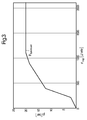
- the procedure is essentially based on two different strategies for controlling or regulating the electric motor 14, which are explained as follows using the characteristic diagram in FIG. 2 and the setpoint curve in FIG. 3.
- a delivery performance map is shown as an example in FIG. 2, by means of which the control strategy for the generation of the electrical control current I mot is described.
- the flow rate P flow of the pump 18 is plotted against the drive motor speed n mot in the characteristic diagram.
- the straight lines P flow, max and P flow, min indicate the maximum or minimum delivery capacity of the pump used depending on the drive motor speed n mot .
- the straight line P flow linear characterizes the delivery capacity of a similar pump 18 which is driven linearly or rigidly (conventionally) by the drive motor. Between the straight lines P flow, max and P flow, min there is an area in which the flow rate P flow of the pump 18 can be controlled or varied by appropriate control of the electric motor 14.
- control curves P flow , -30 ° C, P flow, 40 ° C, and P flow, 100 ° C are shown, on the basis of which the flow rate P flow of the pump 18 for the different operating oil temperatures -30 ° C, 40 ° C and 100 ° C is controlled.
- a control curve can be specified for any temperature with which the desired delivery rates P flow of the pump 18 can be controlled.
- the control curve P flow, -30 ° C specifies , for example, that the delivery rate P flow of the pump 18 is kept at zero for drive motor speeds n mot below 400 rpm in order to facilitate the starting process by preventing the drag torque that occurs during operation of the pump 18.
- the generated control current I mot (200, -30) then generates the speed and direction of rotation to be applied by the electric motor in order to keep the delivery rate P flow of the pump 18 at zero.
- the procedure is similar for other operating points. For example, the delivery performance map at operating oil temperatures of around -30 ° C.
- a drive motor speed of 1000 rpm specifies a delivery performance P flow of the pump 18 of approximately 22.5 L / min.
- the control current I mot (1000, -30) generated by the control unit 54 then generates the speed and direction of rotation to be applied by the electric motor in order to bring the delivery rate P flow of the pump 18 to 22.5 liters / min.
- the delivery performance map also shows that, compared to a linear (rigid) driven pump, the delivery performance can be adapted very well to the operating requirements.
- T oil 100 ° C.
- the control strategy which is based on a speed and temperature control, makes it possible to vary the delivery rate P flow of the pump 18 in a relatively wide characteristic map and to respond to the various operating requirements in a largely optimized manner compared to a conventional linearly driven pump.
- FIG. 3 An exemplary engine speed-dependent setpoint pressure curve is shown in FIG. 3, on which an alternative control strategy based on pressure measurement is based.
- a setpoint value p system that is dependent on the engine speed is set here for the system pressure P system of the transmission control block 20, which is determined by regulating the speed of the electric motor 14 or regulating the delivery rate P flow of the pump 18 should set n mot for the different drive motor speeds.
- the input motor speed n mot supplied by the tachometer 56 and the currently prevailing system pressure P system determined by the pressure sensor 52 serve as input variables for the control or regulation of the electric motor 14 for each control cycle.
- the setpoint value value P system which is associated with the drive motor speed n mot , is determined from the setpoint curve given in the memory of the control computer and is compared by the control computer with the system pressure P system .
- the difference between the two variables (P system, target , P system ) serves as a control variable for the control current I mot of the electric motor 14.
- the electric motor 14 is now driven faster or slower until the predetermined set pressure value p system, target established.
- This control cycle is repeated in accordance with predefined control intervals, so that in all operating states the setpoint p system, which is predefined in accordance with the setpoint curve, is to be maintained for the system pressure p system of the transmission control block 20.
- a cold start aid for the drive motor 12 is then also possible by setting the target pressure value to zero when the temperature falls below a temperature limit and thus controlling the auxiliary motor 14 in such a way that a drag torque generated by the pump 18 is reduced or canceled can be.
- This arrangement is beneficial, if only a direction of rotation of the auxiliary motor 14 for the adjustment or Control of the conveyor unit 18 is used and a Standstill of the auxiliary motor 14 supporting torque to be applied does not have to be applied by the auxiliary motor 14 itself.
- freewheel 58 can for example on the Drive shaft 32 of auxiliary motor 14 to sun gear 36 be provided. This drives the sun gear 36 allowed by the auxiliary motor 14, but a backward torque flow via the sun gear directly through the connection on the housing side 60 of the freewheel 58 intercepted.
Landscapes
- Engineering & Computer Science (AREA)
- Mechanical Engineering (AREA)
- General Engineering & Computer Science (AREA)
- Control Of Transmission Device (AREA)
- Details And Applications Of Rotary Liquid Pumps (AREA)
- Vending Machines For Individual Products (AREA)
- General Details Of Gearings (AREA)
- Linear Motors (AREA)
- Rotary Pumps (AREA)
Applications Claiming Priority (2)
| Application Number | Priority Date | Filing Date | Title |
|---|---|---|---|
| DE10306418 | 2003-02-15 | ||
| DE10306418A DE10306418A1 (de) | 2003-02-15 | 2003-02-15 | Antriebsanordnung für ein Förderaggregat |
Publications (3)
| Publication Number | Publication Date |
|---|---|
| EP1484532A2 true EP1484532A2 (fr) | 2004-12-08 |
| EP1484532A3 EP1484532A3 (fr) | 2005-11-23 |
| EP1484532B1 EP1484532B1 (fr) | 2008-04-23 |
Family
ID=32747902
Family Applications (1)
| Application Number | Title | Priority Date | Filing Date |
|---|---|---|---|
| EP04100495A Expired - Lifetime EP1484532B1 (fr) | 2003-02-15 | 2004-02-10 | Dispositif d'entraînement pour une ensemble d'alimentation |
Country Status (4)
| Country | Link |
|---|---|
| US (1) | US20040161340A1 (fr) |
| EP (1) | EP1484532B1 (fr) |
| AT (1) | ATE393332T1 (fr) |
| DE (2) | DE10306418A1 (fr) |
Cited By (4)
| Publication number | Priority date | Publication date | Assignee | Title |
|---|---|---|---|---|
| DE102006008430A1 (de) * | 2006-02-23 | 2007-08-30 | Zf Friedrichshafen Ag | Antriebseinrichtung für die Ölpumpe eines Kraftfahrzeuggetriebes |
| DE102006048050A1 (de) * | 2006-10-11 | 2008-04-17 | Bayerische Motoren Werke Ag | Pumpenanordnung und Verfahren zum Betreiben derselben |
| WO2016078692A1 (fr) * | 2014-11-17 | 2016-05-26 | Coreteq Systems Ltd | Actionneur électrique |
| WO2018137730A1 (fr) * | 2017-01-27 | 2018-08-02 | Renk Aktiengesellschaft | Transmission, système d'entraînement comprenant une transmission et procédé permettant de faire fonctionner le système d'entraînement |
Families Citing this family (22)
| Publication number | Priority date | Publication date | Assignee | Title |
|---|---|---|---|---|
| US7054738B1 (en) * | 2005-10-17 | 2006-05-30 | Ford Global Technologies, Llc | Method for estimating engine friction torque |
| JP4742822B2 (ja) | 2005-11-10 | 2011-08-10 | 株式会社デンソー | 車両用交流発電機 |
| DE102007051007A1 (de) * | 2007-10-25 | 2009-04-30 | Bayerische Motoren Werke Aktiengesellschaft | Angetriebenes Nebenaggregat eines Kraftfahrzeugs |
| FR2934321B1 (fr) * | 2008-07-25 | 2013-09-27 | Hispano Suiza Sa | Regulation du debit de carburant preleve dans un circuit carburant d'un aeronef propulse par un moteur. |
| JP2010243047A (ja) * | 2009-04-03 | 2010-10-28 | Honda Motor Co Ltd | 温水供給装置 |
| US8714942B2 (en) | 2009-06-09 | 2014-05-06 | Magna Powertrain Inc. | Dual power input fluid pump |
| DE102011013487B4 (de) | 2011-03-10 | 2017-08-24 | Audi Ag | Kraftfahrzeug mit Getriebe und Getriebeölpumpe |
| US20160047205A1 (en) * | 2013-11-15 | 2016-02-18 | COREteQ Systems Ltd. | Electric actuator |
| CN103775303B (zh) * | 2014-01-07 | 2016-03-02 | 徐州徐工施维英机械有限公司 | 一种机械式砂浆泵 |
| FR3048675B1 (fr) * | 2016-03-14 | 2022-02-18 | Snecma | Alimentation en air d'un circuit de conditionnement d'air d'une cabine d'un aeronef |
| DE102018101082B4 (de) * | 2018-01-18 | 2021-03-18 | Iav Gmbh Ingenieurgesellschaft Auto Und Verkehr | Antriebsanordnung zum Antrieb von wenigstens drei Fluidpumpen |
| GB2570475B (en) | 2018-01-26 | 2020-04-08 | Rolls Royce Plc | Cabin blower system |
| GB2570478A (en) | 2018-01-26 | 2019-07-31 | Rolls Royce Plc | Cabin blower system |
| DE102020206509A1 (de) | 2020-05-26 | 2021-12-02 | Zf Friedrichshafen Ag | Verfahren zum Betrieb einer Pumpenantriebseinheit |
| DE102020206513A1 (de) | 2020-05-26 | 2021-12-02 | Zf Friedrichshafen Ag | Verfahren zum Betrieb einer Pumpenantriebseinheit |
| DE102020206512A1 (de) | 2020-05-26 | 2021-12-02 | Zf Friedrichshafen Ag | Verfahren zum Betrieb einer Pumpe |
| US11585428B2 (en) | 2020-09-08 | 2023-02-21 | Deere & Company | Cold start lubricant distribution systems and work vehicles including the same |
| DE102020214393A1 (de) | 2020-11-17 | 2022-05-19 | Zf Friedrichshafen Ag | Verfahren und Steuergerät zum Betrieb einer Pumpenantriebseinheit und eines Getriebes |
| US11313302B1 (en) * | 2021-07-06 | 2022-04-26 | Hyundai Motor Company | Engine idle speed optimization |
| US12489343B2 (en) * | 2021-10-21 | 2025-12-02 | Rivian Ip Holdings, Llc | Oil warming system and method for an electric motor |
| CN115507162B (zh) * | 2022-10-21 | 2025-07-11 | 山西荣盛志达科技有限责任公司 | 一种基于机电一体化行星调速的功率平衡装置及运行方法 |
| DE102023209154A1 (de) * | 2023-09-20 | 2025-03-20 | Zf Friedrichshafen Ag | Verfahren zur Bestimmung einer Temperatur einer Fluidfördereinrichtung |
Family Cites Families (11)
| Publication number | Priority date | Publication date | Assignee | Title |
|---|---|---|---|---|
| DE2504867A1 (de) * | 1975-02-06 | 1976-08-19 | Helmut Koerner | Antriebsaggregat |
| US4514991A (en) * | 1983-10-17 | 1985-05-07 | Carrier Corporation | Variable speed drive motor system with inverter control |
| US5039281A (en) * | 1989-12-26 | 1991-08-13 | General Electric Company | Method and apparatus for supplying compressed air to auxiliary systems of a vehicle |
| US5628234A (en) * | 1995-10-30 | 1997-05-13 | Gec-Marconi Aerospace Inc. | Fail-free actuator assembly |
| US5867996A (en) * | 1997-02-24 | 1999-02-09 | Denso Corporation | Compressor control device for vehicle air conditioner |
| US5947854A (en) * | 1997-05-08 | 1999-09-07 | Worksmart Energy Enterprises, Inc. | Combined variable-speed drive and speed reducer for pumps and fans |
| US6234769B1 (en) * | 1997-07-09 | 2001-05-22 | Denso Corporation | Hybrid type compressor driven by engine and electric motor |
| US6073456A (en) * | 1997-10-09 | 2000-06-13 | Denso Corporation | Air-conditioning device for hybrid vehicle |
| DE19831997A1 (de) * | 1998-07-16 | 2000-01-20 | Ewald Hennel | Verfahren zur Regelung des Drucks eines Fluids |
| DE10104635A1 (de) * | 2001-02-02 | 2002-10-02 | Joma Hydromechanic Gmbh | Verfahren zum Aufrechterhalten einer konstanten Ausgangsgröße einer Förderpumpe, z.B. ihres Fördervolumens, die von einer in ihrer Drehzahl variablen Antriebsvorrichtung angetrieben wird, sowie Vorrichtung zur Durchführung des Verfahrens |
| US6742350B2 (en) * | 2001-11-03 | 2004-06-01 | Nippon Soken, Inc. | Hybrid compressor device |
-
2003
- 2003-02-15 DE DE10306418A patent/DE10306418A1/de not_active Withdrawn
- 2003-11-25 US US10/721,493 patent/US20040161340A1/en not_active Abandoned
-
2004
- 2004-02-10 AT AT04100495T patent/ATE393332T1/de active
- 2004-02-10 DE DE502004006882T patent/DE502004006882D1/de not_active Expired - Lifetime
- 2004-02-10 EP EP04100495A patent/EP1484532B1/fr not_active Expired - Lifetime
Cited By (8)
| Publication number | Priority date | Publication date | Assignee | Title |
|---|---|---|---|---|
| DE102006008430A1 (de) * | 2006-02-23 | 2007-08-30 | Zf Friedrichshafen Ag | Antriebseinrichtung für die Ölpumpe eines Kraftfahrzeuggetriebes |
| US8066492B2 (en) | 2006-02-23 | 2011-11-29 | Zf Friedrichshafen Ag | Drive device for the oil pump of a motor vehicle transmission |
| DE102006048050A1 (de) * | 2006-10-11 | 2008-04-17 | Bayerische Motoren Werke Ag | Pumpenanordnung und Verfahren zum Betreiben derselben |
| WO2016078692A1 (fr) * | 2014-11-17 | 2016-05-26 | Coreteq Systems Ltd | Actionneur électrique |
| GB2548514A (en) * | 2014-11-17 | 2017-09-20 | Correteq Systems Ltd | Electric actuator |
| GB2548514B (en) * | 2014-11-17 | 2021-05-26 | Coreteq Systems Ltd | Electric actuator |
| WO2018137730A1 (fr) * | 2017-01-27 | 2018-08-02 | Renk Aktiengesellschaft | Transmission, système d'entraînement comprenant une transmission et procédé permettant de faire fonctionner le système d'entraînement |
| US11085524B2 (en) | 2017-01-27 | 2021-08-10 | Renk Gmbh | Transmission, drive assembly having a transmission, and method for operating the drive assembly |
Also Published As
| Publication number | Publication date |
|---|---|
| EP1484532A3 (fr) | 2005-11-23 |
| DE502004006882D1 (de) | 2008-06-05 |
| EP1484532B1 (fr) | 2008-04-23 |
| DE10306418A1 (de) | 2004-08-26 |
| US20040161340A1 (en) | 2004-08-19 |
| ATE393332T1 (de) | 2008-05-15 |
Similar Documents
| Publication | Publication Date | Title |
|---|---|---|
| EP1484532B1 (fr) | Dispositif d'entraînement pour une ensemble d'alimentation | |
| EP1896713B1 (fr) | Systeme d'injection de carburant pour moteur a combustion interne | |
| DE10213598B4 (de) | Ölpumpe für eine Brennkraftmaschine und Verfahren zum Betrieb derselben | |
| DE10051356B4 (de) | Getriebe für eine Hubkolbenbrennkraftmaschine | |
| DE3623676C2 (fr) | ||
| EP1537335A1 (fr) | Dispositif de regulation de la puissance de pompage d'une pompe a lubrifiant d'automobile | |
| DE102005013657A1 (de) | Zahnradgetriebe eines Kraftfahrzeugs und Verfahren zur Steuerung der Ölversorgungseinrichtung eines Zahnradgetriebes | |
| DE3333647A1 (de) | Regelbare schmiermittelpumpe | |
| DE10329215A1 (de) | Antriebsvorrichtung für eine Getriebe-Ölpumpe und Verfahren zum Betreiben derselben | |
| EP3371423B1 (fr) | Dispositif de refoulement pour le refoulement d'huile | |
| DE19902408C2 (de) | Automatgetriebe für Fahrzeuge mit einem hydrodynamischen Wandler | |
| EP0724068A1 (fr) | Système d'amenée d'huile | |
| EP2017114B1 (fr) | Véhicule doté d'un entraînement de roulement hydrostatique | |
| EP1911964B1 (fr) | Pompe à carburant haute pression et système d'injection de carburant pour moteur à combustion interne | |
| DE10361374A1 (de) | Motorschmiermittelkreis mit zwei Pumpen | |
| DE3012760A1 (de) | Fluessigkeitsheizungssystem | |
| EP1586785B1 (fr) | Arrangement et méthode d'accouplement d'un compresseur d'air à l'arbre d'entraînement d'un moteur de combustion | |
| DE10042749A1 (de) | Getriebe | |
| EP0931209B1 (fr) | Unite motrice a pompe hydraulique thermoregulee | |
| EP3784906B1 (fr) | Système de distribution d'huile lubrifiante réglable pour moteurs à combustion interne | |
| DE19941841A1 (de) | Selbstfahrende landwirtschaftliche Arbeitsmaschine | |
| DE112009001698B4 (de) | Anordnung und Verfahren zur unterbrechungsfreien Versorgung eines Hydrauliksystems mit einem Fluid | |
| DE19950423A1 (de) | Verfahren und Vorrichtung zur Schmierung eines Getriebes eines Kraftfahrzeuges | |
| DE19950422B4 (de) | Vorrichtung zur Schmierung eines Getriebes eines Kraftfahrzeuges | |
| DE3626013C1 (en) | Hydrostatic fan drive |
Legal Events
| Date | Code | Title | Description |
|---|---|---|---|
| PUAI | Public reference made under article 153(3) epc to a published international application that has entered the european phase |
Free format text: ORIGINAL CODE: 0009012 |
|
| AK | Designated contracting states |
Kind code of ref document: A2 Designated state(s): AT BE BG CH CY CZ DE DK EE ES FI FR GB GR HU IE IT LI LU MC NL PT RO SE SI SK TR |
|
| AX | Request for extension of the european patent |
Extension state: AL LT LV MK |
|
| PUAL | Search report despatched |
Free format text: ORIGINAL CODE: 0009013 |
|
| AK | Designated contracting states |
Kind code of ref document: A3 Designated state(s): AT BE BG CH CY CZ DE DK EE ES FI FR GB GR HU IE IT LI LU MC NL PT RO SE SI SK TR |
|
| AX | Request for extension of the european patent |
Extension state: AL LT LV MK |
|
| 17P | Request for examination filed |
Effective date: 20060523 |
|
| AKX | Designation fees paid |
Designated state(s): AT BE BG CH CY CZ DE DK EE ES FI FR GB GR HU IE IT LI LU MC NL PT RO SE SI SK TR |
|
| 17Q | First examination report despatched |
Effective date: 20060913 |
|
| 17Q | First examination report despatched |
Effective date: 20060913 |
|
| 17Q | First examination report despatched |
Effective date: 20060913 |
|
| GRAP | Despatch of communication of intention to grant a patent |
Free format text: ORIGINAL CODE: EPIDOSNIGR1 |
|
| GRAS | Grant fee paid |
Free format text: ORIGINAL CODE: EPIDOSNIGR3 |
|
| GRAA | (expected) grant |
Free format text: ORIGINAL CODE: 0009210 |
|
| AK | Designated contracting states |
Kind code of ref document: B1 Designated state(s): AT BE BG CH CY CZ DE DK EE ES FI FR GB GR HU IE IT LI LU MC NL PT RO SE SI SK TR |
|
| REG | Reference to a national code |
Ref country code: GB Ref legal event code: FG4D Free format text: NOT ENGLISH |
|
| REG | Reference to a national code |
Ref country code: CH Ref legal event code: EP |
|
| REF | Corresponds to: |
Ref document number: 502004006882 Country of ref document: DE Date of ref document: 20080605 Kind code of ref document: P |
|
| REG | Reference to a national code |
Ref country code: IE Ref legal event code: FG4D Free format text: LANGUAGE OF EP DOCUMENT: GERMAN |
|
| PG25 | Lapsed in a contracting state [announced via postgrant information from national office to epo] |
Ref country code: SI Free format text: LAPSE BECAUSE OF FAILURE TO SUBMIT A TRANSLATION OF THE DESCRIPTION OR TO PAY THE FEE WITHIN THE PRESCRIBED TIME-LIMIT Effective date: 20080423 |
|
| NLV1 | Nl: lapsed or annulled due to failure to fulfill the requirements of art. 29p and 29m of the patents act | ||
| PG25 | Lapsed in a contracting state [announced via postgrant information from national office to epo] |
Ref country code: PT Free format text: LAPSE BECAUSE OF FAILURE TO SUBMIT A TRANSLATION OF THE DESCRIPTION OR TO PAY THE FEE WITHIN THE PRESCRIBED TIME-LIMIT Effective date: 20080923 Ref country code: NL Free format text: LAPSE BECAUSE OF FAILURE TO SUBMIT A TRANSLATION OF THE DESCRIPTION OR TO PAY THE FEE WITHIN THE PRESCRIBED TIME-LIMIT Effective date: 20080423 Ref country code: ES Free format text: LAPSE BECAUSE OF FAILURE TO SUBMIT A TRANSLATION OF THE DESCRIPTION OR TO PAY THE FEE WITHIN THE PRESCRIBED TIME-LIMIT Effective date: 20080803 Ref country code: BG Free format text: LAPSE BECAUSE OF FAILURE TO SUBMIT A TRANSLATION OF THE DESCRIPTION OR TO PAY THE FEE WITHIN THE PRESCRIBED TIME-LIMIT Effective date: 20080723 |
|
| REG | Reference to a national code |
Ref country code: IE Ref legal event code: FD4D |
|
| ET | Fr: translation filed | ||
| PG25 | Lapsed in a contracting state [announced via postgrant information from national office to epo] |
Ref country code: CZ Free format text: LAPSE BECAUSE OF FAILURE TO SUBMIT A TRANSLATION OF THE DESCRIPTION OR TO PAY THE FEE WITHIN THE PRESCRIBED TIME-LIMIT Effective date: 20080423 Ref country code: IE Free format text: LAPSE BECAUSE OF FAILURE TO SUBMIT A TRANSLATION OF THE DESCRIPTION OR TO PAY THE FEE WITHIN THE PRESCRIBED TIME-LIMIT Effective date: 20080423 Ref country code: DK Free format text: LAPSE BECAUSE OF FAILURE TO SUBMIT A TRANSLATION OF THE DESCRIPTION OR TO PAY THE FEE WITHIN THE PRESCRIBED TIME-LIMIT Effective date: 20080423 Ref country code: SE Free format text: LAPSE BECAUSE OF FAILURE TO SUBMIT A TRANSLATION OF THE DESCRIPTION OR TO PAY THE FEE WITHIN THE PRESCRIBED TIME-LIMIT Effective date: 20080723 |
|
| PG25 | Lapsed in a contracting state [announced via postgrant information from national office to epo] |
Ref country code: SK Free format text: LAPSE BECAUSE OF FAILURE TO SUBMIT A TRANSLATION OF THE DESCRIPTION OR TO PAY THE FEE WITHIN THE PRESCRIBED TIME-LIMIT Effective date: 20080423 Ref country code: RO Free format text: LAPSE BECAUSE OF FAILURE TO SUBMIT A TRANSLATION OF THE DESCRIPTION OR TO PAY THE FEE WITHIN THE PRESCRIBED TIME-LIMIT Effective date: 20080423 |
|
| PLBE | No opposition filed within time limit |
Free format text: ORIGINAL CODE: 0009261 |
|
| STAA | Information on the status of an ep patent application or granted ep patent |
Free format text: STATUS: NO OPPOSITION FILED WITHIN TIME LIMIT |
|
| 26N | No opposition filed |
Effective date: 20090126 |
|
| PG25 | Lapsed in a contracting state [announced via postgrant information from national office to epo] |
Ref country code: EE Free format text: LAPSE BECAUSE OF FAILURE TO SUBMIT A TRANSLATION OF THE DESCRIPTION OR TO PAY THE FEE WITHIN THE PRESCRIBED TIME-LIMIT Effective date: 20080423 |
|
| BERE | Be: lapsed |
Owner name: DEERE & CY Effective date: 20090228 |
|
| PG25 | Lapsed in a contracting state [announced via postgrant information from national office to epo] |
Ref country code: MC Free format text: LAPSE BECAUSE OF NON-PAYMENT OF DUE FEES Effective date: 20090228 |
|
| REG | Reference to a national code |
Ref country code: CH Ref legal event code: PL |
|
| PG25 | Lapsed in a contracting state [announced via postgrant information from national office to epo] |
Ref country code: LI Free format text: LAPSE BECAUSE OF NON-PAYMENT OF DUE FEES Effective date: 20090228 Ref country code: CH Free format text: LAPSE BECAUSE OF NON-PAYMENT OF DUE FEES Effective date: 20090228 |
|
| PG25 | Lapsed in a contracting state [announced via postgrant information from national office to epo] |
Ref country code: BE Free format text: LAPSE BECAUSE OF NON-PAYMENT OF DUE FEES Effective date: 20090228 |
|
| PG25 | Lapsed in a contracting state [announced via postgrant information from national office to epo] |
Ref country code: GR Free format text: LAPSE BECAUSE OF FAILURE TO SUBMIT A TRANSLATION OF THE DESCRIPTION OR TO PAY THE FEE WITHIN THE PRESCRIBED TIME-LIMIT Effective date: 20080724 |
|
| PG25 | Lapsed in a contracting state [announced via postgrant information from national office to epo] |
Ref country code: LU Free format text: LAPSE BECAUSE OF NON-PAYMENT OF DUE FEES Effective date: 20090210 |
|
| PG25 | Lapsed in a contracting state [announced via postgrant information from national office to epo] |
Ref country code: HU Free format text: LAPSE BECAUSE OF FAILURE TO SUBMIT A TRANSLATION OF THE DESCRIPTION OR TO PAY THE FEE WITHIN THE PRESCRIBED TIME-LIMIT Effective date: 20081024 |
|
| PG25 | Lapsed in a contracting state [announced via postgrant information from national office to epo] |
Ref country code: TR Free format text: LAPSE BECAUSE OF FAILURE TO SUBMIT A TRANSLATION OF THE DESCRIPTION OR TO PAY THE FEE WITHIN THE PRESCRIBED TIME-LIMIT Effective date: 20080423 |
|
| PG25 | Lapsed in a contracting state [announced via postgrant information from national office to epo] |
Ref country code: CY Free format text: LAPSE BECAUSE OF FAILURE TO SUBMIT A TRANSLATION OF THE DESCRIPTION OR TO PAY THE FEE WITHIN THE PRESCRIBED TIME-LIMIT Effective date: 20080423 |
|
| PGFP | Annual fee paid to national office [announced via postgrant information from national office to epo] |
Ref country code: FI Payment date: 20140227 Year of fee payment: 11 |
|
| PGFP | Annual fee paid to national office [announced via postgrant information from national office to epo] |
Ref country code: IT Payment date: 20140224 Year of fee payment: 11 Ref country code: AT Payment date: 20140121 Year of fee payment: 11 |
|
| REG | Reference to a national code |
Ref country code: AT Ref legal event code: MM01 Ref document number: 393332 Country of ref document: AT Kind code of ref document: T Effective date: 20150210 |
|
| PG25 | Lapsed in a contracting state [announced via postgrant information from national office to epo] |
Ref country code: FI Free format text: LAPSE BECAUSE OF NON-PAYMENT OF DUE FEES Effective date: 20150210 |
|
| PG25 | Lapsed in a contracting state [announced via postgrant information from national office to epo] |
Ref country code: AT Free format text: LAPSE BECAUSE OF NON-PAYMENT OF DUE FEES Effective date: 20150210 |
|
| PG25 | Lapsed in a contracting state [announced via postgrant information from national office to epo] |
Ref country code: IT Free format text: LAPSE BECAUSE OF NON-PAYMENT OF DUE FEES Effective date: 20150210 |
|
| REG | Reference to a national code |
Ref country code: FR Ref legal event code: PLFP Year of fee payment: 13 |
|
| REG | Reference to a national code |
Ref country code: FR Ref legal event code: PLFP Year of fee payment: 14 |
|
| REG | Reference to a national code |
Ref country code: FR Ref legal event code: PLFP Year of fee payment: 15 |
|
| PGFP | Annual fee paid to national office [announced via postgrant information from national office to epo] |
Ref country code: FR Payment date: 20230223 Year of fee payment: 20 |
|
| PGFP | Annual fee paid to national office [announced via postgrant information from national office to epo] |
Ref country code: GB Payment date: 20230227 Year of fee payment: 20 Ref country code: DE Payment date: 20230119 Year of fee payment: 20 |
|
| REG | Reference to a national code |
Ref country code: DE Ref legal event code: R071 Ref document number: 502004006882 Country of ref document: DE |
|
| REG | Reference to a national code |
Ref country code: GB Ref legal event code: PE20 Expiry date: 20240209 |
|
| PG25 | Lapsed in a contracting state [announced via postgrant information from national office to epo] |
Ref country code: GB Free format text: LAPSE BECAUSE OF EXPIRATION OF PROTECTION Effective date: 20240209 |