EP1484540A1 - Membrane de commande, en particulier pour soupapes pneumatiques - Google Patents
Membrane de commande, en particulier pour soupapes pneumatiques Download PDFInfo
- Publication number
- EP1484540A1 EP1484540A1 EP04012235A EP04012235A EP1484540A1 EP 1484540 A1 EP1484540 A1 EP 1484540A1 EP 04012235 A EP04012235 A EP 04012235A EP 04012235 A EP04012235 A EP 04012235A EP 1484540 A1 EP1484540 A1 EP 1484540A1
- Authority
- EP
- European Patent Office
- Prior art keywords
- membrane
- flow control
- control assembly
- valve
- port
- Prior art date
- Legal status (The legal status is an assumption and is not a legal conclusion. Google has not performed a legal analysis and makes no representation as to the accuracy of the status listed.)
- Granted
Links
- 239000012528 membrane Substances 0.000 title claims abstract description 76
- 239000013013 elastic material Substances 0.000 claims abstract description 4
- 239000000463 material Substances 0.000 claims description 8
- 238000007789 sealing Methods 0.000 claims description 8
- 239000012530 fluid Substances 0.000 claims description 6
- 238000001746 injection moulding Methods 0.000 claims 1
- 230000035945 sensitivity Effects 0.000 description 3
- 230000000694 effects Effects 0.000 description 2
- 230000001627 detrimental effect Effects 0.000 description 1
- 238000000605 extraction Methods 0.000 description 1
- 230000000670 limiting effect Effects 0.000 description 1
- 238000004519 manufacturing process Methods 0.000 description 1
- 238000000465 moulding Methods 0.000 description 1
- 239000004753 textile Substances 0.000 description 1
Images

Classifications
-
- F—MECHANICAL ENGINEERING; LIGHTING; HEATING; WEAPONS; BLASTING
- F16—ENGINEERING ELEMENTS AND UNITS; GENERAL MEASURES FOR PRODUCING AND MAINTAINING EFFECTIVE FUNCTIONING OF MACHINES OR INSTALLATIONS; THERMAL INSULATION IN GENERAL
- F16K—VALVES; TAPS; COCKS; ACTUATING-FLOATS; DEVICES FOR VENTING OR AERATING
- F16K31/00—Actuating devices; Operating means; Releasing devices
- F16K31/12—Actuating devices; Operating means; Releasing devices actuated by fluid
- F16K31/126—Actuating devices; Operating means; Releasing devices actuated by fluid the fluid acting on a diaphragm, bellows, or the like
- F16K31/1262—Actuating devices; Operating means; Releasing devices actuated by fluid the fluid acting on a diaphragm, bellows, or the like one side of the diaphragm being spring loaded
-
- F—MECHANICAL ENGINEERING; LIGHTING; HEATING; WEAPONS; BLASTING
- F16—ENGINEERING ELEMENTS AND UNITS; GENERAL MEASURES FOR PRODUCING AND MAINTAINING EFFECTIVE FUNCTIONING OF MACHINES OR INSTALLATIONS; THERMAL INSULATION IN GENERAL
- F16K—VALVES; TAPS; COCKS; ACTUATING-FLOATS; DEVICES FOR VENTING OR AERATING
- F16K11/00—Multiple-way valves, e.g. mixing valves; Pipe fittings incorporating such valves
- F16K11/02—Multiple-way valves, e.g. mixing valves; Pipe fittings incorporating such valves with all movable sealing faces moving as one unit
- F16K11/04—Multiple-way valves, e.g. mixing valves; Pipe fittings incorporating such valves with all movable sealing faces moving as one unit comprising only lift valves
- F16K11/048—Multiple-way valves, e.g. mixing valves; Pipe fittings incorporating such valves with all movable sealing faces moving as one unit comprising only lift valves with valve seats positioned between movable valve members
Definitions
- the present invention relates to a membrane, particularly but not exclusively for controlled vacuum, which can be used in pneumatic valves having a membrane that actuates a flow control assembly.
- the present invention further relates to a pneumatic valve of the type having a membrane that actuates a flow control assembly, particularly but not exclusively of the indirect electropneumatically-operated type.
- Pneumatic valves of the type with a membrane that actuates a flow control assembly are currently known.
- Such valves are constituted by a valve body inside which there is a receptacle that slidingly accommodates a flow control assembly formed by a supporting stem for two conical flow control elements, which are arranged so as to be mutually opposite and face corresponding sealing seats, against which they respectively abut during the operation of said valve.
- the receptacle is functionally connected to a first port for the main supply of the fluid on which the valve acts and to a second port and a third port, each of which is functionally connected to a corresponding environment located outside the valve, respectively the user system and the discharge.
- Such valves are provided with a flat circular membrane, which is locked by means of its outer rim on said valve body and is centrally locked on the flow control assembly.
- the membrane forms in the receptacle a first chamber for connection between the first, second and third port and a second chamber, which is functionally connected to an actuation unit, for example a typical solenoid-based electropneumatic unit.
- an actuation unit for example a typical solenoid-based electropneumatic unit.
- the first port for the main supply of fluid is further functionally connected to said electropneumatic actuation unit.
- the first supply port is isolated and the second and third ports are connected; in this step, the port for connecting the supply to the electropneumatic actuation unit also is isolated.
- the second chamber is in partial vacuum and attracts the membrane, and therefore the flow control assembly, in a direction that isolates the first feed port.
- the first (pressurized) feed port is connected to the second chamber; in this way, the membrane (and the flow control assembly) are moved so as to connect the first port to the user system, isolating the discharge.
- the pressure in the second chamber must also overcome the contrast force of the elastic spring for return to the initial position.
- the main drawback relates to the membrane for actuating the flow control assembly.
- valves must in fact operate for a very large number of operating cycles, and accordingly the membranes of the valves are subject to a very large number of deformation cycles.
- the membranes must be thick enough to ensure the necessary strength.
- the materials also must be chosen so as to resist for a long time; said membranes are typically made out of blanked portions of sheets of rubber reinforced with textile inserts.
- the actuation of the valve must overcome the elastic contrast of the membrane (the larger its size, the greater the contrast force) and of the elastic spring for return to position; accordingly, intense forces are required in order to actuate the valve.
- annular recess is provided in conical flow control elements (which are generally injection-molded) proximate to the inclined sealing region (the choice of the position of the recess is due to easy extraction of the flow control element from the mold).
- the position of the recess is critical, since due to wear caused by the large number of operating cycles of the valve and due to possible inaccuracies in molding, it may reduce the degree of tightness of the valve.
- the aim of the present invention is to provide a membrane, particularly for controlled vacuum, usable in pneumatic valves having a membrane that actuates a flow control assembly, that solves the drawbacks noted above in known types.
- an object of the present invention is to provide a membrane, particularly for controlled vacuum, usable in pneumatic valves having a membrane that actuates a flow control assembly, that is particularly resistant to a large number of operating cycles.
- Another object of the present invention is to provide a membrane, particularly for controlled vacuum, usable in pneumatic valves having a membrane that actuates a flow control assembly, that is more compact and is made of less expensive material than known types, thus leading to a cost reduction.
- a further object of the present invention is to provide a membrane, particularly for controlled vacuum, usable in pneumatic valves having a membrane that actuates a flow control assembly, that allows higher sensitivity in the actuation of the valves to which it is applied.
- a still further object of the present invention is to provide a pneumatic valve of the type with a membrane that actuates a flow control assembly, particularly of the indirect electropneumatically-actuated type, that solves the problems noted in the corresponding known valves.
- a membrane particularly for controlled vacuum, usable in pneumatic valves having a membrane that actuates a flow control assembly, constituted by a disk made of at least partially elastic material, characterized in that said disk has, in transverse cross-section, at least one region that has an undulated profile.
- the present invention comprises a pneumatic valve of the type having a membrane that actuates a flow control assembly, particularly of the indirect electropneumatically-actuated type, comprising said membrane.
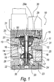
- a pneumatic valve of the type having a membrane that actuates a flow control assembly is generally designated by the reference numeral 10.
- the valve is of the three-way two-position (3/2) type, with closed centers (NC).
- the pneumatic valve 10 comprises a valve body 11, which contains a receptacle 12 in which a flow control assembly 13 is arranged so that it can slide; the flow control assembly is formed by a stem 14 that supports two mutually opposite conical flow control elements 15.
- the two conical flow control elements 15 face corresponding sealing seats 16, against which they abut respectively during the operation of the valve 10.
- the receptacle 12 is functionally connected to a first port 17 for the main supply of the fluid on which the valve acts and to a second port 18 and a third port 19, each of which is functionally connected to a corresponding environment that lies outside the valve, such as the user system and the discharge.
- the valve body 11 is composed of a central block 20, which is open at its two ends, by a first endplate 21 and by a second endplate 22 which lies opposite the first endplate 21; the endplates 21 and 22 are coupled to the central block 20 by means of threaded elements 23.
- the stem 14 is formed by a central bobbin-like portion 25, on the ends of which the conical flow control elements 15 are arranged in abutment.
- a cylinder 26 is arranged in series to the flow control element 15 that is arranged toward the first endplate 21, and a locking disk 27 is arranged in series to the cylinder.
- Both conical flow control elements 15 have, on the opposite side with respect to the respective sealing seats 16 and coaxially to their own axis, an annular recess 24.
- a membrane 50 for actuating the flow control assembly 13 is provided between the valve body 11 and the flow control assembly.
- the membrane 50 forms, in the receptacle 12, a first chamber 28 for connection between the first, second and third ports 17, 18 and 19, and a second chamber 29, which is functionally connected to an electropneumatic actuation unit 30, which is of a per se known type.
- the first main fluid supply port 17 is further functionally connected to the electropneumatic actuation unit 30 by means of a channel 31, which is internal to the block 20 and to the first endplate 21.
- the electropneumatic actuation unit 30 is functionally connected to the second chamber 29 by means of a duct 29a.
- Means 32 for return to the non-actuated position, in this case the closed-center position, are associated with the flow control assembly 13 and are constituted by a helical spring 33, which is arranged between the second endplate 22 and an abutment formed on the flow control assembly on the opposite side of the membrane with respect to the bobbin 25.
- the membrane 50 is constituted by a disk 51, which is made of at least partially elastic material, such as for example an injection-molded polymeric material.
- the disk 51 has, in this embodiment, a region with an undulated profile 52.
- the disk 51 is provided axially with a hole 53 for centering and locking on the flow control element 13, which is actuated by said membrane.
- the region 52 having an undulated profile is formed, when the membrane is in the active position, by an undulation that has, from the center toward the outside of the disk 51, a convex portion 54 that is directed toward the flow control assembly 13 and a concave portion 55 in series to the convex portion 54.
- the region 52 having an undulated profile is therefore formed on a ring.
- transverse cross-sections of the outer rim 56 and of the inner rim 57 of the disk 51 with said hole are partially circular, with diameters that are larger than the thickness of the region 52 having an undulated profile.
- Portions 58 of the disk 51 that are contiguous to the outer and inner rims 56 and 57 are flat, and their thickness is comprised between the diameter of the rims 56 and 57 and the diameter of the region 52 having an undulated profile.
- the membrane 50 is locked by its outer rim 56 on the valve body 11 and by its inner rim 57 on the flow control assembly 13.
- the membrane 50 is sandwiched by its outer rim 56 between the central block 20 and the first endplate 21.
- the membrane is sandwiched between the cylinder 26 and the locking disk 27.
- the membrane 50 is substantially in contact with the cylinder 26 of the flow control assembly 13 along the convex portion of the region 52 having an undulated profile.
- outer rim 56 and the inner rim 57 are accommodated in corresponding complementarily shaped annular slots (not designated by reference numerals in the figures), which are formed in the flow control assembly 13 and the valve body 11 and ensure stable locking of the membrane.
- the first feed port 17 is isolated and the second and third ports 18 and 19 are connected; in this step, the channel 31 for connection to the electropneumatic actuation unit 30 is also isolated.
- the second chamber 29 is in partial vacuum and draws the membrane, and therefore the flow control assembly 13, in a direction that isolates the first feed port, moving the corresponding conical flow control element 15 into abutment on the corresponding sealing seat 16.
- the first feed path 17 (which is pressurized) is connected to the second chamber 29; in this manner, the membrane 50 is moved (and accordingly the flow control assembly 13 is made to perform a translational motion) so as to connect the first port 17 to the user, isolating the discharge.
- the pressure in the second chamber 29 must also overcome the contrast force of the elastic spring 33.
- the undulation of the membrane 50, with the convex portion 54 and the concave portion 55, allows a longer stroke of the membrane and accordingly of the flow control assembly 13 without exceeding the critical threshold of the strength of the material of which the membrane is made; it is therefore possible to use less expensive materials for an equal strength.
- the undulation of the membrane 50, with the convex portion 54 and the concave portion 55, produces a spring-like effect, which assists the movement of the flow control assembly during its actuation, increasing the speed of the assembly and therefore increasing the overall speed of the valve.
- the reduced thicknesses of the undulated part 52 allow the use of less material with respect to known membranes, reducing the production costs of said membranes.
- the materials employed may be any according to requirements and to the state of the art.
Landscapes
- Engineering & Computer Science (AREA)
- General Engineering & Computer Science (AREA)
- Mechanical Engineering (AREA)
- Fluid-Driven Valves (AREA)
- Fluid-Damping Devices (AREA)
Applications Claiming Priority (2)
| Application Number | Priority Date | Filing Date | Title |
|---|---|---|---|
| ITPD20030043U | 2003-06-03 | ||
| IT000043U ITPD20030043U1 (it) | 2003-06-03 | 2003-06-03 | Membrana, particolarmente per vuoto asservito, utilizzabile in valvole pneumatiche a membrana comandante un gruppo di otturazione, e valvola pneumatica utilizzante detta membrana. |
Publications (2)
| Publication Number | Publication Date |
|---|---|
| EP1484540A1 true EP1484540A1 (fr) | 2004-12-08 |
| EP1484540B1 EP1484540B1 (fr) | 2007-11-07 |
Family
ID=33156356
Family Applications (1)
| Application Number | Title | Priority Date | Filing Date |
|---|---|---|---|
| EP04012235A Expired - Lifetime EP1484540B1 (fr) | 2003-06-03 | 2004-05-24 | Membrane de commande, en particulier pour soupapes pneumatiques |
Country Status (4)
| Country | Link |
|---|---|
| EP (1) | EP1484540B1 (fr) |
| AT (1) | ATE377725T1 (fr) |
| DE (1) | DE602004009858D1 (fr) |
| IT (1) | ITPD20030043U1 (fr) |
Cited By (4)
| Publication number | Priority date | Publication date | Assignee | Title |
|---|---|---|---|---|
| DE102017126307A1 (de) * | 2017-11-09 | 2019-05-09 | Delo Industrie Klebstoffe Gmbh & Co. Kgaa | Dosiervorrichtung sowie Verfahren zum Dosieren von flüssigen Medien |
| WO2020226557A1 (fr) * | 2019-05-09 | 2020-11-12 | Delaval Holding Ab | Membrane pour déplacer un disque de soupape d'une soupape de commande, et soupape de commande |
| EP3805618A1 (fr) * | 2019-10-12 | 2021-04-14 | Hamilton Sundstrand Corporation | Ensemble servo-vanne |
| DE102013010556B4 (de) | 2013-06-25 | 2025-11-06 | Steuerungstechnik Staiger GmbH & Co. KG | Ventil |
Citations (2)
| Publication number | Priority date | Publication date | Assignee | Title |
|---|---|---|---|---|
| US3415284A (en) * | 1965-11-11 | 1968-12-10 | Lucifer Sa | Flap valve |
| FR2206468A1 (fr) * | 1972-11-13 | 1974-06-07 | Arisland Kjell |
-
2003
- 2003-06-03 IT IT000043U patent/ITPD20030043U1/it unknown
-
2004
- 2004-05-24 EP EP04012235A patent/EP1484540B1/fr not_active Expired - Lifetime
- 2004-05-24 AT AT04012235T patent/ATE377725T1/de not_active IP Right Cessation
- 2004-05-24 DE DE602004009858T patent/DE602004009858D1/de not_active Expired - Lifetime
Patent Citations (2)
| Publication number | Priority date | Publication date | Assignee | Title |
|---|---|---|---|---|
| US3415284A (en) * | 1965-11-11 | 1968-12-10 | Lucifer Sa | Flap valve |
| FR2206468A1 (fr) * | 1972-11-13 | 1974-06-07 | Arisland Kjell |
Cited By (10)
| Publication number | Priority date | Publication date | Assignee | Title |
|---|---|---|---|---|
| DE102013010556B4 (de) | 2013-06-25 | 2025-11-06 | Steuerungstechnik Staiger GmbH & Co. KG | Ventil |
| DE102017126307A1 (de) * | 2017-11-09 | 2019-05-09 | Delo Industrie Klebstoffe Gmbh & Co. Kgaa | Dosiervorrichtung sowie Verfahren zum Dosieren von flüssigen Medien |
| WO2019091984A1 (fr) * | 2017-11-09 | 2019-05-16 | Delo Industrie Klebstoffe Gmbh & Co. Kgaa | Dispositif de dosage ainsi que procédé pour le dosage de milieux liquides |
| WO2020226557A1 (fr) * | 2019-05-09 | 2020-11-12 | Delaval Holding Ab | Membrane pour déplacer un disque de soupape d'une soupape de commande, et soupape de commande |
| CN113795695A (zh) * | 2019-05-09 | 2021-12-14 | 利拉伐控股有限公司 | 用于移动控制阀的阀盘的膜以及控制阀 |
| EP3966479B1 (fr) * | 2019-05-09 | 2023-08-09 | DeLaval Holding AB | Membrane pour déplacer un disque de soupape d'une soupape de commande, et soupape de commande |
| US11746923B2 (en) | 2019-05-09 | 2023-09-05 | Delaval Holding Ab | Membrane for a moving a valve disk of a control valve, and a control valve |
| CN113795695B (zh) * | 2019-05-09 | 2024-02-02 | 利拉伐控股有限公司 | 用于移动控制阀的阀盘的膜以及控制阀 |
| EP3805618A1 (fr) * | 2019-10-12 | 2021-04-14 | Hamilton Sundstrand Corporation | Ensemble servo-vanne |
| US11359731B2 (en) | 2019-10-12 | 2022-06-14 | Hamilton Sundstrand Corporation | Servo valve assembly |
Also Published As
| Publication number | Publication date |
|---|---|
| EP1484540B1 (fr) | 2007-11-07 |
| ATE377725T1 (de) | 2007-11-15 |
| DE602004009858D1 (de) | 2007-12-20 |
| ITPD20030043U1 (it) | 2004-12-04 |
Similar Documents
| Publication | Publication Date | Title |
|---|---|---|
| US4295631A (en) | Solenoid operated valve | |
| CA2292006C (fr) | Membrane a renfort modifie | |
| US7059578B2 (en) | Diaphragm and hydraulically-operated valve using same | |
| US6089262A (en) | Retained seat check valve | |
| JPH06341560A (ja) | ダイヤフラム弁 | |
| JPH0366986A (ja) | 中空ステムの具えた3方向ポペットバルブ | |
| US5609343A (en) | Sealing rings for spool valves | |
| GB1339868A (en) | Vehicle brake actuating system | |
| EP1193401A2 (fr) | Soupape de commande à pressions multiples avec clapet à bille | |
| JP4579406B2 (ja) | 流体制御バルブ | |
| US4955582A (en) | Weirless diaphragm valve | |
| US5699825A (en) | Double seat flow control valve | |
| JPH05502645A (ja) | アンチロック付流体圧ブレーキ装置用マスタブレーキシリンダ | |
| US20010007354A1 (en) | Two-port valve | |
| EP1484540B1 (fr) | Membrane de commande, en particulier pour soupapes pneumatiques | |
| KR0177544B1 (ko) | 포핏형 방향전환밸브 | |
| US6357339B1 (en) | Multi-stage piston actuator | |
| US3874629A (en) | Fluid operated needle valve | |
| MX2008011599A (es) | Valvula de diafragma de una pieza de membrana doble. | |
| WO2005080838A2 (fr) | Membrane pour vanne pilote | |
| JPS62177379A (ja) | エアパイロツト式流路切換弁 | |
| CN111089183A (zh) | 一种气动密封组合控制阀 | |
| US20020024033A1 (en) | Manual operating means for valves | |
| CA2364904A1 (fr) | Soupape pour bouteille de gaz | |
| GB2045403A (en) | Pivotal ball valve |
Legal Events
| Date | Code | Title | Description |
|---|---|---|---|
| PUAI | Public reference made under article 153(3) epc to a published international application that has entered the european phase |
Free format text: ORIGINAL CODE: 0009012 |
|
| AK | Designated contracting states |
Kind code of ref document: A1 Designated state(s): AT BE BG CH CY CZ DE DK EE ES FI FR GB GR HU IE IT LI LU MC NL PL PT RO SE SI SK TR |
|
| AX | Request for extension of the european patent |
Extension state: AL HR LT LV MK |
|
| 17P | Request for examination filed |
Effective date: 20050606 |
|
| AKX | Designation fees paid |
Designated state(s): AT BE BG CH CY CZ DE DK EE ES FI FR GB GR HU IE IT LI LU MC NL PL PT RO SE SI SK TR |
|
| GRAP | Despatch of communication of intention to grant a patent |
Free format text: ORIGINAL CODE: EPIDOSNIGR1 |
|
| GRAS | Grant fee paid |
Free format text: ORIGINAL CODE: EPIDOSNIGR3 |
|
| GRAA | (expected) grant |
Free format text: ORIGINAL CODE: 0009210 |
|
| AK | Designated contracting states |
Kind code of ref document: B1 Designated state(s): AT BE BG CH CY CZ DE DK EE ES FI FR GB GR HU IE IT LI LU MC NL PL PT RO SE SI SK TR |
|
| REG | Reference to a national code |
Ref country code: GB Ref legal event code: FG4D |
|
| REG | Reference to a national code |
Ref country code: IE Ref legal event code: FG4D |
|
| REG | Reference to a national code |
Ref country code: CH Ref legal event code: EP |
|
| REF | Corresponds to: |
Ref document number: 602004009858 Country of ref document: DE Date of ref document: 20071220 Kind code of ref document: P |
|
| PG25 | Lapsed in a contracting state [announced via postgrant information from national office to epo] |
Ref country code: NL Free format text: LAPSE BECAUSE OF FAILURE TO SUBMIT A TRANSLATION OF THE DESCRIPTION OR TO PAY THE FEE WITHIN THE PRESCRIBED TIME-LIMIT Effective date: 20071107 Ref country code: SE Free format text: LAPSE BECAUSE OF FAILURE TO SUBMIT A TRANSLATION OF THE DESCRIPTION OR TO PAY THE FEE WITHIN THE PRESCRIBED TIME-LIMIT Effective date: 20080207 Ref country code: CH Free format text: LAPSE BECAUSE OF FAILURE TO SUBMIT A TRANSLATION OF THE DESCRIPTION OR TO PAY THE FEE WITHIN THE PRESCRIBED TIME-LIMIT Effective date: 20071107 Ref country code: ES Free format text: LAPSE BECAUSE OF FAILURE TO SUBMIT A TRANSLATION OF THE DESCRIPTION OR TO PAY THE FEE WITHIN THE PRESCRIBED TIME-LIMIT Effective date: 20080218 Ref country code: LI Free format text: LAPSE BECAUSE OF FAILURE TO SUBMIT A TRANSLATION OF THE DESCRIPTION OR TO PAY THE FEE WITHIN THE PRESCRIBED TIME-LIMIT Effective date: 20071107 |
|
| NLV1 | Nl: lapsed or annulled due to failure to fulfill the requirements of art. 29p and 29m of the patents act | ||
| PG25 | Lapsed in a contracting state [announced via postgrant information from national office to epo] |
Ref country code: SI Free format text: LAPSE BECAUSE OF FAILURE TO SUBMIT A TRANSLATION OF THE DESCRIPTION OR TO PAY THE FEE WITHIN THE PRESCRIBED TIME-LIMIT Effective date: 20071107 Ref country code: PL Free format text: LAPSE BECAUSE OF FAILURE TO SUBMIT A TRANSLATION OF THE DESCRIPTION OR TO PAY THE FEE WITHIN THE PRESCRIBED TIME-LIMIT Effective date: 20071107 Ref country code: BG Free format text: LAPSE BECAUSE OF FAILURE TO SUBMIT A TRANSLATION OF THE DESCRIPTION OR TO PAY THE FEE WITHIN THE PRESCRIBED TIME-LIMIT Effective date: 20080207 |
|
| REG | Reference to a national code |
Ref country code: CH Ref legal event code: PL |
|
| PG25 | Lapsed in a contracting state [announced via postgrant information from national office to epo] |
Ref country code: AT Free format text: LAPSE BECAUSE OF FAILURE TO SUBMIT A TRANSLATION OF THE DESCRIPTION OR TO PAY THE FEE WITHIN THE PRESCRIBED TIME-LIMIT Effective date: 20071107 |
|
| PG25 | Lapsed in a contracting state [announced via postgrant information from national office to epo] |
Ref country code: CZ Free format text: LAPSE BECAUSE OF FAILURE TO SUBMIT A TRANSLATION OF THE DESCRIPTION OR TO PAY THE FEE WITHIN THE PRESCRIBED TIME-LIMIT Effective date: 20071107 Ref country code: DK Free format text: LAPSE BECAUSE OF FAILURE TO SUBMIT A TRANSLATION OF THE DESCRIPTION OR TO PAY THE FEE WITHIN THE PRESCRIBED TIME-LIMIT Effective date: 20071107 |
|
| EN | Fr: translation not filed | ||
| PG25 | Lapsed in a contracting state [announced via postgrant information from national office to epo] |
Ref country code: BE Free format text: LAPSE BECAUSE OF FAILURE TO SUBMIT A TRANSLATION OF THE DESCRIPTION OR TO PAY THE FEE WITHIN THE PRESCRIBED TIME-LIMIT Effective date: 20071107 Ref country code: RO Free format text: LAPSE BECAUSE OF FAILURE TO SUBMIT A TRANSLATION OF THE DESCRIPTION OR TO PAY THE FEE WITHIN THE PRESCRIBED TIME-LIMIT Effective date: 20071107 Ref country code: SK Free format text: LAPSE BECAUSE OF FAILURE TO SUBMIT A TRANSLATION OF THE DESCRIPTION OR TO PAY THE FEE WITHIN THE PRESCRIBED TIME-LIMIT Effective date: 20071107 |
|
| PLBE | No opposition filed within time limit |
Free format text: ORIGINAL CODE: 0009261 |
|
| STAA | Information on the status of an ep patent application or granted ep patent |
Free format text: STATUS: NO OPPOSITION FILED WITHIN TIME LIMIT |
|
| PG25 | Lapsed in a contracting state [announced via postgrant information from national office to epo] |
Ref country code: PT Free format text: LAPSE BECAUSE OF FAILURE TO SUBMIT A TRANSLATION OF THE DESCRIPTION OR TO PAY THE FEE WITHIN THE PRESCRIBED TIME-LIMIT Effective date: 20080407 |
|
| 26N | No opposition filed |
Effective date: 20080808 |
|
| PG25 | Lapsed in a contracting state [announced via postgrant information from national office to epo] |
Ref country code: FR Free format text: LAPSE BECAUSE OF FAILURE TO SUBMIT A TRANSLATION OF THE DESCRIPTION OR TO PAY THE FEE WITHIN THE PRESCRIBED TIME-LIMIT Effective date: 20080822 Ref country code: DE Free format text: LAPSE BECAUSE OF FAILURE TO SUBMIT A TRANSLATION OF THE DESCRIPTION OR TO PAY THE FEE WITHIN THE PRESCRIBED TIME-LIMIT Effective date: 20080208 |
|
| PG25 | Lapsed in a contracting state [announced via postgrant information from national office to epo] |
Ref country code: MC Free format text: LAPSE BECAUSE OF NON-PAYMENT OF DUE FEES Effective date: 20080531 |
|
| GBPC | Gb: european patent ceased through non-payment of renewal fee |
Effective date: 20080524 |
|
| PG25 | Lapsed in a contracting state [announced via postgrant information from national office to epo] |
Ref country code: GR Free format text: LAPSE BECAUSE OF FAILURE TO SUBMIT A TRANSLATION OF THE DESCRIPTION OR TO PAY THE FEE WITHIN THE PRESCRIBED TIME-LIMIT Effective date: 20080208 |
|
| PG25 | Lapsed in a contracting state [announced via postgrant information from national office to epo] |
Ref country code: FI Free format text: LAPSE BECAUSE OF FAILURE TO SUBMIT A TRANSLATION OF THE DESCRIPTION OR TO PAY THE FEE WITHIN THE PRESCRIBED TIME-LIMIT Effective date: 20071107 |
|
| PG25 | Lapsed in a contracting state [announced via postgrant information from national office to epo] |
Ref country code: IE Free format text: LAPSE BECAUSE OF NON-PAYMENT OF DUE FEES Effective date: 20080526 Ref country code: EE Free format text: LAPSE BECAUSE OF FAILURE TO SUBMIT A TRANSLATION OF THE DESCRIPTION OR TO PAY THE FEE WITHIN THE PRESCRIBED TIME-LIMIT Effective date: 20071107 |
|
| PG25 | Lapsed in a contracting state [announced via postgrant information from national office to epo] |
Ref country code: GB Free format text: LAPSE BECAUSE OF NON-PAYMENT OF DUE FEES Effective date: 20080524 |
|
| PG25 | Lapsed in a contracting state [announced via postgrant information from national office to epo] |
Ref country code: CY Free format text: LAPSE BECAUSE OF FAILURE TO SUBMIT A TRANSLATION OF THE DESCRIPTION OR TO PAY THE FEE WITHIN THE PRESCRIBED TIME-LIMIT Effective date: 20071107 |
|
| PG25 | Lapsed in a contracting state [announced via postgrant information from national office to epo] |
Ref country code: HU Free format text: LAPSE BECAUSE OF FAILURE TO SUBMIT A TRANSLATION OF THE DESCRIPTION OR TO PAY THE FEE WITHIN THE PRESCRIBED TIME-LIMIT Effective date: 20080508 Ref country code: LU Free format text: LAPSE BECAUSE OF NON-PAYMENT OF DUE FEES Effective date: 20080524 |
|
| PG25 | Lapsed in a contracting state [announced via postgrant information from national office to epo] |
Ref country code: TR Free format text: LAPSE BECAUSE OF FAILURE TO SUBMIT A TRANSLATION OF THE DESCRIPTION OR TO PAY THE FEE WITHIN THE PRESCRIBED TIME-LIMIT Effective date: 20071107 |
|
| PGFP | Annual fee paid to national office [announced via postgrant information from national office to epo] |
Ref country code: IT Payment date: 20230509 Year of fee payment: 20 |