EP1484543A1 - Verbindungsvorrichtung für Rohre - Google Patents
Verbindungsvorrichtung für Rohre Download PDFInfo
- Publication number
- EP1484543A1 EP1484543A1 EP04291309A EP04291309A EP1484543A1 EP 1484543 A1 EP1484543 A1 EP 1484543A1 EP 04291309 A EP04291309 A EP 04291309A EP 04291309 A EP04291309 A EP 04291309A EP 1484543 A1 EP1484543 A1 EP 1484543A1
- Authority
- EP
- European Patent Office
- Prior art keywords
- ring
- nut
- cutting ring
- rings
- thrust ring
- Prior art date
- Legal status (The legal status is an assumption and is not a legal conclusion. Google has not performed a legal analysis and makes no representation as to the accuracy of the status listed.)
- Granted
Links
- 238000007789 sealing Methods 0.000 claims abstract description 24
- 230000000149 penetrating effect Effects 0.000 claims abstract description 3
- 230000006835 compression Effects 0.000 claims description 3
- 238000007906 compression Methods 0.000 claims description 3
- 230000008878 coupling Effects 0.000 claims 1
- 238000010168 coupling process Methods 0.000 claims 1
- 238000005859 coupling reaction Methods 0.000 claims 1
- 239000002184 metal Substances 0.000 description 7
- 230000035515 penetration Effects 0.000 description 6
- 230000008901 benefit Effects 0.000 description 4
- 238000002788 crimping Methods 0.000 description 3
- 230000006378 damage Effects 0.000 description 3
- 208000027418 Wounds and injury Diseases 0.000 description 2
- 238000004873 anchoring Methods 0.000 description 2
- 230000004888 barrier function Effects 0.000 description 2
- 230000000694 effects Effects 0.000 description 2
- 208000014674 injury Diseases 0.000 description 2
- 208000031968 Cadaver Diseases 0.000 description 1
- 235000008612 Gnetum gnemon Nutrition 0.000 description 1
- 240000000018 Gnetum gnemon Species 0.000 description 1
- 239000011324 bead Substances 0.000 description 1
- 230000003750 conditioning effect Effects 0.000 description 1
- 230000002950 deficient Effects 0.000 description 1
- 230000006866 deterioration Effects 0.000 description 1
- 229920001971 elastomer Polymers 0.000 description 1
- 239000000806 elastomer Substances 0.000 description 1
- 239000013536 elastomeric material Substances 0.000 description 1
- 239000012530 fluid Substances 0.000 description 1
- 238000009434 installation Methods 0.000 description 1
- 239000000463 material Substances 0.000 description 1
- 230000032696 parturition Effects 0.000 description 1
- 230000002035 prolonged effect Effects 0.000 description 1
- 239000000565 sealant Substances 0.000 description 1
- 238000010008 shearing Methods 0.000 description 1
- 230000008646 thermal stress Effects 0.000 description 1
Images

Classifications
-
- F—MECHANICAL ENGINEERING; LIGHTING; HEATING; WEAPONS; BLASTING
- F16—ENGINEERING ELEMENTS AND UNITS; GENERAL MEASURES FOR PRODUCING AND MAINTAINING EFFECTIVE FUNCTIONING OF MACHINES OR INSTALLATIONS; THERMAL INSULATION IN GENERAL
- F16L—PIPES; JOINTS OR FITTINGS FOR PIPES; SUPPORTS FOR PIPES, CABLES OR PROTECTIVE TUBING; MEANS FOR THERMAL INSULATION IN GENERAL
- F16L19/00—Joints in which sealing surfaces are pressed together by means of a member, e.g. a swivel nut, screwed on, or into, one of the joint parts
- F16L19/08—Joints in which sealing surfaces are pressed together by means of a member, e.g. a swivel nut, screwed on, or into, one of the joint parts with metal rings which bite into the wall of the pipe
- F16L19/10—Joints in which sealing surfaces are pressed together by means of a member, e.g. a swivel nut, screwed on, or into, one of the joint parts with metal rings which bite into the wall of the pipe the profile of the ring being altered
- F16L19/12—Joints in which sealing surfaces are pressed together by means of a member, e.g. a swivel nut, screwed on, or into, one of the joint parts with metal rings which bite into the wall of the pipe the profile of the ring being altered with additional sealing means
-
- F—MECHANICAL ENGINEERING; LIGHTING; HEATING; WEAPONS; BLASTING
- F16—ENGINEERING ELEMENTS AND UNITS; GENERAL MEASURES FOR PRODUCING AND MAINTAINING EFFECTIVE FUNCTIONING OF MACHINES OR INSTALLATIONS; THERMAL INSULATION IN GENERAL
- F16L—PIPES; JOINTS OR FITTINGS FOR PIPES; SUPPORTS FOR PIPES, CABLES OR PROTECTIVE TUBING; MEANS FOR THERMAL INSULATION IN GENERAL
- F16L19/00—Joints in which sealing surfaces are pressed together by means of a member, e.g. a swivel nut, screwed on, or into, one of the joint parts
- F16L19/08—Joints in which sealing surfaces are pressed together by means of a member, e.g. a swivel nut, screwed on, or into, one of the joint parts with metal rings which bite into the wall of the pipe
- F16L19/10—Joints in which sealing surfaces are pressed together by means of a member, e.g. a swivel nut, screwed on, or into, one of the joint parts with metal rings which bite into the wall of the pipe the profile of the ring being altered
- F16L19/103—Joints in which sealing surfaces are pressed together by means of a member, e.g. a swivel nut, screwed on, or into, one of the joint parts with metal rings which bite into the wall of the pipe the profile of the ring being altered with more than one ring per pipe end being used
Definitions
- the present invention relates to fittings for pipes, in particular for metal pipes intended for to convey fluids at high pressure.
- These devices comprise in a known manner since long a body in which penetrates one end piping to be connected on the side of a threaded end externally of this body which comprises a housing of the end of the piping with a section conical inlet called cone at 24 °.
- a nut is can be screwed onto the threaded end and at least an annular piece is pressed between the body and the nut to ensure the mechanical attachment of the body to the piping and on the other hand the tightness between this body and this piping.
- document DE 19 709464 which describes an annular piece whose nose before forms the anchoring part which is crimped onto the tube and whose rear portion has an O-ring in a throat whose inside diameter is less than the outside diameter of the tube.
- sealing is ensured by a metal front ring that enters the cone at 24 ° until a heel comes to a stop at the mouth of the cone.
- Mechanical stowage is ensured by a rear ring pushing the front ring which owns an extension of the engaging front ring side in a cone of the latter forcing the extension to be shrink radially to crimp on the tube and a extension of the side of the nut which also cooperates with a conical surface of this nut to also be set on the tube.
- the so-called front ring sealant wears an elastomeric nose that only penetrates in the cone at 24 ° of the body, and on the other hand, the ring rear so-called cutting ring only bites into the tube by its extension on the side of the sealing ring.
- the present invention is intended to remedy disadvantages of previous devices by clearly separating the function of anchoring and mechanical connection of the sealing function.
- Such an embodiment has the advantage of have a sealing element, for example a seal ring or a flat ring seal, whose internal diameter is, before compression, greater than the diameter of tube to be connected, so that when setting up of the device, that is to say after having engaged the nut on the threaded end of the body, the penetration of the end of the tube does not cause snagging or seal injury.
- a sealing element for example a seal ring or a flat ring seal
- this sealing element is housed in an internal chambering of the thrust ring, open on the side of a rear axial collar of the ring cutting that can penetrate, preferably with a slight tightening.
- the annular seal whether it is flat or toric, is totally protected in the chambering at right of the collar.
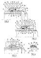
- the device for sealing connection or connection of a pipe 1 to a body 2 provided with a threaded end 2 a and a receiving housing 3 of the tube 1 having an inlet section 3 a conical cone at 24 °, 4 comprises a nut with a tapped chamber 4 has a cutting ring 5 and a thrust ring 6.
- the cutting ring 5 has a front extension or nose 5a which here carries two cutting edges 5b and 5c, this extension into the interior of the conical section 3a of the body 2 when the nut 4 is tightened onto the end piece Thread 2.
- the rear portion of the cutting ring 5 is limited by a shoulder 5 d forming a thrust face beyond which extends an axial flange 5 e facing toward the thrust ring 6.
- the thrust ring 6 comprises a front face 6a facing the shoulder 5 d and a recess 6b for receiving the axial flange 5 e of the cutting ring and forming a housing in which is disposed an annular gasket 7 of plastic material or elastomeric material capable of being compressed between the extension 5 e which enters the recess 6 b and the end surface 6 c of this recess.
- the rear portion of the thrust ring 6 has a frustoconical outer surface 6 d to cooperate with a corresponding frustoconical face 8 belonging to the rear wall of the nut 4.
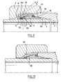
- This wall is provided with a hole 9 for passage of the tube 1 to be connected, either a mandrel 10 ( Figure 8) made for example of plastic, which is divided into a cylindrical section 11, tubular here, internal to the chamber 4 and has an outer section 12 to the nut, by a shoulder 13.
- the inner section 11 has the right to the cutting ring 5 housed in the chamber 4 has a bead 14 which cooperates by friction with the cutting ring 5 so as to form a retaining means of the two rings 5 and 6 to the inside the chamber 4 a of the nut 4.
- the outer part 12 of the mandrel 10 constitutes the support for a sign identifying 15 of the connecting device, such as for example the nominal diameter of the tube to which the device is intended.
- this set wherein the outer section 12 of the mandrel 10 is located opposite the nose 5a of the ring 5, can be attached temporarily to the end of the body 2 which may be partially screwed on the end piece threaded 2a, the mandrel 10 forming a closure for the body before the installation of the pipe to be connected.
- the set of nut, cutting ring and thrust ring components, held in one unit by the mandrel 10 is much simpler to handle and package than if the components were separated.
- the mandrel 10 can be introduced into the nut 4 by the threaded chamber 4a.
- the shoulder 13 bears on the mouth of this room.
- the free end of the tubular portion 11 of the mandrel 10 is then housed in the orifice 7 and in this case the plug function of the threaded end can not be ensured.
- the cutting ring 5 has a bearing shoulder 5 f which limits its penetration inside the cone 3 has 24 °.
- This shoulder 5 f constitutes directly or through a small recess, the support for an additional sealing element 16, here in the form of a cylindrical ring.
- This element 16 being located at the base of the nose 5 has bearing the cutting edges 5b and 5c.
- the seal 16 is axially compressed by the end of the threaded nose 2 is moving closer to the shoulder end 5 f of the cutting ring of 5, to form a second sealing barrier between the body 2 and the Rings.
- the advantage of this arrangement of the sealing elements lies in the protection they enjoy before the connection is made.
- the seal 7 may be provided with an internal diameter greater than the outer diameter of the tube 7 so that the introduction of the tube 7 does not risk causing injury or damage to the seal.
- the arrangement of the seal 16 which does not penetrate inside the cone at 24 °, does not present the risk of being torn off during this penetration and then being poorly arranged to ensure effective sealing.
- the seal 16 is here replaced by a 17 gasket which cooperates with the outlet of the conical orifice 3 has on the end face of the body 2.
- FIG. 5 shows the elements already described in FIGS. 1 and 2, with a ring geometry cutting and thrust identical to that of Figure 4 but using cylindrical seals 21, 22 instead of being toric.
- FIG 6 there is more than one seal 23 which is housed in the recess 6 b of the thrust ring 6.
- the cutting ring 5 is summarized in a cylindrical sleeve of diametric dimension substantially identical to 5 the extension e of Figure 1, so that the ring 5 can be compressed with the rear wall 6c of the counterbore 6 b, a portion 23a of the gasket 23 in the same manner that is compressed the gasket 7 of figures 1 and 2.
- a sleeve 23 b of the seal 23 extends tubularly part 23a thereof to cap the cutting ring 5 and to protrude beyond the end 6 e of the thrust ring 6 which cooperates, as in Figure 4 with the end face of the threaded end 2a of the body 2.
- the advantage of this arrangement lies in the fact that the seal 23 may be a holding means of the rings 5 and 6 assembled together by friction with the sleeve 23 b compressed together, these three components then forming a unit housed in the a chamber 4 has nut 4.
- Figure 7 shows a preferred variant of Figure 6 wherein the ring 6 has on its push rear part 6 has means 24 (here a sharp edge), which are able to cut a weakened portion of the seal 23 forming the connection between the portion 23a of the seal and the sleeve 23 b thereof and to allow a metal contact - metal between the rings 5 and 6 to the shearing area of the joint.
- means 24 here a sharp edge
- FIGS. 9 and 10 show an alternative embodiment of FIGS. 1 and 2.
- the angle of the cone of the face 8 of the nut is more open than that of the rear face 6 d of the thrust ring (angular difference marked a in Figure 9).
- the axial extension 5th at the back of the cutting ring 5 is thicker than the 6b chambering of the thrust ring whose entry is surrounded by a surface conical 26 which cooperates with the end of extension 5e, preferably provided with a chamfer 25.
Landscapes
- Engineering & Computer Science (AREA)
- General Engineering & Computer Science (AREA)
- Mechanical Engineering (AREA)
- Joints With Pressure Members (AREA)
- Gasket Seals (AREA)
Applications Claiming Priority (2)
| Application Number | Priority Date | Filing Date | Title |
|---|---|---|---|
| FR0306666 | 2003-06-03 | ||
| FR0306666A FR2855864B1 (fr) | 2003-06-03 | 2003-06-03 | Dispositif de raccordement pour tuyauteries |
Publications (2)
| Publication Number | Publication Date |
|---|---|
| EP1484543A1 true EP1484543A1 (de) | 2004-12-08 |
| EP1484543B1 EP1484543B1 (de) | 2008-11-05 |
Family
ID=33155644
Family Applications (1)
| Application Number | Title | Priority Date | Filing Date |
|---|---|---|---|
| EP20040291309 Expired - Lifetime EP1484543B1 (de) | 2003-06-03 | 2004-05-24 | Verbindungsvorrichtung für Rohre |
Country Status (3)
| Country | Link |
|---|---|
| EP (1) | EP1484543B1 (de) |
| DE (1) | DE602004017536D1 (de) |
| FR (1) | FR2855864B1 (de) |
Cited By (1)
| Publication number | Priority date | Publication date | Assignee | Title |
|---|---|---|---|---|
| US20240077155A1 (en) * | 2021-01-22 | 2024-03-07 | Danfoss Power Solutions Ii Technology A/S | Tube connector systems |
Citations (3)
| Publication number | Priority date | Publication date | Assignee | Title |
|---|---|---|---|---|
| US2316806A (en) * | 1941-03-14 | 1943-04-20 | Arthur L Parker | Tube coupling |
| US2511134A (en) * | 1946-05-27 | 1950-06-13 | Anchor Coupling Company Inc | Sleeve type tube coupling |
| WO1997020163A1 (en) * | 1995-11-30 | 1997-06-05 | Fabrizio Minerdo | A connector for high-pressure metal pipes |
-
2003
- 2003-06-03 FR FR0306666A patent/FR2855864B1/fr not_active Expired - Fee Related
-
2004
- 2004-05-24 EP EP20040291309 patent/EP1484543B1/de not_active Expired - Lifetime
- 2004-05-24 DE DE200460017536 patent/DE602004017536D1/de not_active Expired - Lifetime
Patent Citations (3)
| Publication number | Priority date | Publication date | Assignee | Title |
|---|---|---|---|---|
| US2316806A (en) * | 1941-03-14 | 1943-04-20 | Arthur L Parker | Tube coupling |
| US2511134A (en) * | 1946-05-27 | 1950-06-13 | Anchor Coupling Company Inc | Sleeve type tube coupling |
| WO1997020163A1 (en) * | 1995-11-30 | 1997-06-05 | Fabrizio Minerdo | A connector for high-pressure metal pipes |
Cited By (2)
| Publication number | Priority date | Publication date | Assignee | Title |
|---|---|---|---|---|
| US20240077155A1 (en) * | 2021-01-22 | 2024-03-07 | Danfoss Power Solutions Ii Technology A/S | Tube connector systems |
| US12305779B2 (en) * | 2021-01-22 | 2025-05-20 | Danfoss A/S | Tube connector systems |
Also Published As
| Publication number | Publication date |
|---|---|
| FR2855864B1 (fr) | 2005-07-08 |
| FR2855864A1 (fr) | 2004-12-10 |
| EP1484543B1 (de) | 2008-11-05 |
| DE602004017536D1 (de) | 2008-12-18 |
Similar Documents
| Publication | Publication Date | Title |
|---|---|---|
| EP0406144B1 (de) | Abdichtungselemente mit ringförmigem Ankerabsatz | |
| FR2847646A1 (fr) | Raccord de tuyau | |
| CA2360088C (fr) | Dispositif de raccordement rapide d'un tube a un element rigide | |
| FR2826705A1 (fr) | Raccord recuperable adaptable aux extremites d'un tuyau souple arme | |
| EP1561988B1 (de) | Schnellkupplung | |
| FR2737275A1 (fr) | Raccord de tuyaux antiseparation | |
| EP1291568B1 (de) | Schnellkupplung für verformbare Rohre | |
| FR2629891A1 (fr) | Raccord d'assemblage de canalisations notamment pour gaz | |
| EP1489713B1 (de) | Dichte Wanddurchführungsvorrichtung | |
| BE1006081A3 (fr) | Raccord de derivation pour tuyauterie en matiere thermoplastique. | |
| FR2554543A1 (fr) | Raccord pour montage rapide d'un tube de tuyauterie dans un trou taraude | |
| FR2863032A1 (fr) | Raccord a sertir pour tubes multicouches | |
| EP1484543B1 (de) | Verbindungsvorrichtung für Rohre | |
| FR2482251A1 (fr) | Dispositif de raccordement d'un ecrou tournant a l'extremite d'un tuyau du type onduleux | |
| EP1547728A1 (de) | Backe für Pressverbindung | |
| EP1571383B1 (de) | Pressfitting mit einem schneidbaren Prüfring | |
| EP1484542B1 (de) | Verbindungsvorrichtung für Hochdruckfluidleitungen | |
| FR2796122A1 (fr) | Raccord instantane pour tube composite a ame metallique | |
| EP0085010B1 (de) | Selbstschliessende Kupplung insbesondere für ein Fluid oder eine Kühlflüssigkeit | |
| EP1927805A1 (de) | Schutzvorrichtung auf Rohrflanschen zum Spritzschutz | |
| EP0046705B1 (de) | Verbindung zwischen einer Kunststoffleitung und einer metallischen Leitung für eine Flüssigkeit unter Druck | |
| EP0581678A1 (de) | Radiale Spannvorrichtung zum Verbinden von einem Rohr mit einem Rohrende | |
| FR2555285A1 (fr) | Groupe de raccordement a tubulure pour tuyauteries, appareils hydrauliques avec compensation des erreurs de montage | |
| EP1258665A1 (de) | Schnellkupplung für verformbare Rohre | |
| EP3482117B1 (de) | Schaltungselement mit einfachem einlegen |
Legal Events
| Date | Code | Title | Description |
|---|---|---|---|
| PUAI | Public reference made under article 153(3) epc to a published international application that has entered the european phase |
Free format text: ORIGINAL CODE: 0009012 |
|
| AK | Designated contracting states |
Kind code of ref document: A1 Designated state(s): AT BE BG CH CY CZ DE DK EE ES FI FR GB GR HU IE IT LI LU MC NL PL PT RO SE SI SK TR |
|
| AX | Request for extension of the european patent |
Extension state: AL HR LT LV MK |
|
| 17P | Request for examination filed |
Effective date: 20050518 |
|
| AKX | Designation fees paid |
Designated state(s): DE FR GB IT |
|
| GRAP | Despatch of communication of intention to grant a patent |
Free format text: ORIGINAL CODE: EPIDOSNIGR1 |
|
| GRAS | Grant fee paid |
Free format text: ORIGINAL CODE: EPIDOSNIGR3 |
|
| GRAA | (expected) grant |
Free format text: ORIGINAL CODE: 0009210 |
|
| AK | Designated contracting states |
Kind code of ref document: B1 Designated state(s): DE FR GB IT |
|
| REG | Reference to a national code |
Ref country code: GB Ref legal event code: FG4D Free format text: NOT ENGLISH |
|
| REF | Corresponds to: |
Ref document number: 602004017536 Country of ref document: DE Date of ref document: 20081218 Kind code of ref document: P |
|
| PLBE | No opposition filed within time limit |
Free format text: ORIGINAL CODE: 0009261 |
|
| STAA | Information on the status of an ep patent application or granted ep patent |
Free format text: STATUS: NO OPPOSITION FILED WITHIN TIME LIMIT |
|
| 26N | No opposition filed |
Effective date: 20090806 |
|
| PGFP | Annual fee paid to national office [announced via postgrant information from national office to epo] |
Ref country code: GB Payment date: 20140520 Year of fee payment: 11 |
|
| PGFP | Annual fee paid to national office [announced via postgrant information from national office to epo] |
Ref country code: IT Payment date: 20140513 Year of fee payment: 11 |
|
| REG | Reference to a national code |
Ref country code: DE Ref legal event code: R082 Ref document number: 602004017536 Country of ref document: DE Representative=s name: SCHAUMBURG & PARTNER PATENTANWAELTE GBR, DE Ref country code: DE Ref legal event code: R082 Ref document number: 602004017536 Country of ref document: DE Representative=s name: SCHAUMBURG UND PARTNER PATENTANWAELTE MBB, DE |
|
| GBPC | Gb: european patent ceased through non-payment of renewal fee |
Effective date: 20150524 |
|
| PG25 | Lapsed in a contracting state [announced via postgrant information from national office to epo] |
Ref country code: IT Free format text: LAPSE BECAUSE OF NON-PAYMENT OF DUE FEES Effective date: 20150524 |
|
| PG25 | Lapsed in a contracting state [announced via postgrant information from national office to epo] |
Ref country code: GB Free format text: LAPSE BECAUSE OF NON-PAYMENT OF DUE FEES Effective date: 20150524 |
|
| REG | Reference to a national code |
Ref country code: FR Ref legal event code: PLFP Year of fee payment: 13 |
|
| REG | Reference to a national code |
Ref country code: FR Ref legal event code: PLFP Year of fee payment: 14 |
|
| REG | Reference to a national code |
Ref country code: FR Ref legal event code: PLFP Year of fee payment: 15 |
|
| P01 | Opt-out of the competence of the unified patent court (upc) registered |
Effective date: 20230525 |
|
| PGFP | Annual fee paid to national office [announced via postgrant information from national office to epo] |
Ref country code: FR Payment date: 20230523 Year of fee payment: 20 Ref country code: DE Payment date: 20230510 Year of fee payment: 20 |
|
| REG | Reference to a national code |
Ref country code: DE Ref legal event code: R071 Ref document number: 602004017536 Country of ref document: DE |