EP1484547A2 - LED-Lampe für eine Lichtanzeige in einem Flugzeug - Google Patents
LED-Lampe für eine Lichtanzeige in einem Flugzeug Download PDFInfo
- Publication number
- EP1484547A2 EP1484547A2 EP04075390A EP04075390A EP1484547A2 EP 1484547 A2 EP1484547 A2 EP 1484547A2 EP 04075390 A EP04075390 A EP 04075390A EP 04075390 A EP04075390 A EP 04075390A EP 1484547 A2 EP1484547 A2 EP 1484547A2
- Authority
- EP
- European Patent Office
- Prior art keywords
- led light
- bulb
- circuit board
- outer sidewall
- electrical contact
- Prior art date
- Legal status (The legal status is an assumption and is not a legal conclusion. Google has not performed a legal analysis and makes no representation as to the accuracy of the status listed.)
- Withdrawn
Links
- 239000012212 insulator Substances 0.000 claims abstract description 6
- 239000004020 conductor Substances 0.000 claims description 6
- 238000010276 construction Methods 0.000 description 2
- 239000000463 material Substances 0.000 description 2
- 239000000049 pigment Substances 0.000 description 2
- 239000004925 Acrylic resin Substances 0.000 description 1
- 229920000178 Acrylic resin Polymers 0.000 description 1
- 240000002834 Paulownia tomentosa Species 0.000 description 1
- 235000010678 Paulownia tomentosa Nutrition 0.000 description 1
- 241000282849 Ruminantia Species 0.000 description 1
- 229910000639 Spring steel Inorganic materials 0.000 description 1
- 229910000831 Steel Inorganic materials 0.000 description 1
- 238000005286 illumination Methods 0.000 description 1
- 230000002093 peripheral effect Effects 0.000 description 1
- 239000012858 resilient material Substances 0.000 description 1
- 239000010959 steel Substances 0.000 description 1
Images

Classifications
-
- F—MECHANICAL ENGINEERING; LIGHTING; HEATING; WEAPONS; BLASTING
- F21—LIGHTING
- F21S—NON-PORTABLE LIGHTING DEVICES; SYSTEMS THEREOF; VEHICLE LIGHTING DEVICES SPECIALLY ADAPTED FOR VEHICLE EXTERIORS
- F21S8/00—Lighting devices intended for fixed installation
- F21S8/03—Lighting devices intended for fixed installation of surface-mounted type
- F21S8/032—Lighting devices intended for fixed installation of surface-mounted type the surface being a floor or like ground surface, e.g. pavement
-
- B—PERFORMING OPERATIONS; TRANSPORTING
- B64—AIRCRAFT; AVIATION; COSMONAUTICS
- B64D—EQUIPMENT FOR FITTING IN OR TO AIRCRAFT; FLIGHT SUITS; PARACHUTES; ARRANGEMENT OR MOUNTING OF POWER PLANTS OR PROPULSION TRANSMISSIONS IN AIRCRAFT
- B64D47/00—Equipment not otherwise provided for
- B64D47/02—Arrangements or adaptations of signal or lighting devices
-
- F—MECHANICAL ENGINEERING; LIGHTING; HEATING; WEAPONS; BLASTING
- F21—LIGHTING
- F21K—NON-ELECTRIC LIGHT SOURCES USING LUMINESCENCE; LIGHT SOURCES USING ELECTROCHEMILUMINESCENCE; LIGHT SOURCES USING CHARGES OF COMBUSTIBLE MATERIAL; LIGHT SOURCES USING SEMICONDUCTOR DEVICES AS LIGHT-GENERATING ELEMENTS; LIGHT SOURCES NOT OTHERWISE PROVIDED FOR
- F21K9/00—Light sources using semiconductor devices as light-generating elements, e.g. using light-emitting diodes [LED] or lasers
-
- F—MECHANICAL ENGINEERING; LIGHTING; HEATING; WEAPONS; BLASTING
- F21—LIGHTING
- F21K—NON-ELECTRIC LIGHT SOURCES USING LUMINESCENCE; LIGHT SOURCES USING ELECTROCHEMILUMINESCENCE; LIGHT SOURCES USING CHARGES OF COMBUSTIBLE MATERIAL; LIGHT SOURCES USING SEMICONDUCTOR DEVICES AS LIGHT-GENERATING ELEMENTS; LIGHT SOURCES NOT OTHERWISE PROVIDED FOR
- F21K9/00—Light sources using semiconductor devices as light-generating elements, e.g. using light-emitting diodes [LED] or lasers
- F21K9/20—Light sources comprising attachment means
- F21K9/23—Retrofit light sources for lighting devices with a single fitting for each light source, e.g. for substitution of incandescent lamps with bayonet or threaded fittings
-
- F—MECHANICAL ENGINEERING; LIGHTING; HEATING; WEAPONS; BLASTING
- F21—LIGHTING
- F21S—NON-PORTABLE LIGHTING DEVICES; SYSTEMS THEREOF; VEHICLE LIGHTING DEVICES SPECIALLY ADAPTED FOR VEHICLE EXTERIORS
- F21S4/00—Lighting devices or systems using a string or strip of light sources
- F21S4/10—Lighting devices or systems using a string or strip of light sources with light sources attached to loose electric cables, e.g. Christmas tree lights
-
- F—MECHANICAL ENGINEERING; LIGHTING; HEATING; WEAPONS; BLASTING
- F21—LIGHTING
- F21S—NON-PORTABLE LIGHTING DEVICES; SYSTEMS THEREOF; VEHICLE LIGHTING DEVICES SPECIALLY ADAPTED FOR VEHICLE EXTERIORS
- F21S4/00—Lighting devices or systems using a string or strip of light sources
- F21S4/20—Lighting devices or systems using a string or strip of light sources with light sources held by or within elongate supports
-
- F—MECHANICAL ENGINEERING; LIGHTING; HEATING; WEAPONS; BLASTING
- F21—LIGHTING
- F21V—FUNCTIONAL FEATURES OR DETAILS OF LIGHTING DEVICES OR SYSTEMS THEREOF; STRUCTURAL COMBINATIONS OF LIGHTING DEVICES WITH OTHER ARTICLES, NOT OTHERWISE PROVIDED FOR
- F21V19/00—Fastening of light sources or lamp holders
- F21V19/001—Fastening of light sources or lamp holders the light sources being semiconductors devices, e.g. LEDs
- F21V19/0015—Fastening arrangements intended to retain light sources
- F21V19/0025—Fastening arrangements intended to retain light sources the fastening means engaging the conductors of the light source, i.e. providing simultaneous fastening of the light sources and their electric connections
-
- H—ELECTRICITY
- H01—ELECTRIC ELEMENTS
- H01R—ELECTRICALLY-CONDUCTIVE CONNECTIONS; STRUCTURAL ASSOCIATIONS OF A PLURALITY OF MUTUALLY-INSULATED ELECTRICAL CONNECTING ELEMENTS; COUPLING DEVICES; CURRENT COLLECTORS
- H01R33/00—Coupling devices specially adapted for supporting apparatus and having one part acting as a holder providing support and electrical connection via a counterpart which is structurally associated with the apparatus, e.g. lamp holders; Separate parts thereof
- H01R33/05—Two-pole devices
- H01R33/20—Two-pole devices having concentrically or coaxially arranged contacts
-
- B—PERFORMING OPERATIONS; TRANSPORTING
- B64—AIRCRAFT; AVIATION; COSMONAUTICS
- B64D—EQUIPMENT FOR FITTING IN OR TO AIRCRAFT; FLIGHT SUITS; PARACHUTES; ARRANGEMENT OR MOUNTING OF POWER PLANTS OR PROPULSION TRANSMISSIONS IN AIRCRAFT
- B64D11/00—Passenger or crew accommodation; Flight-deck installations not otherwise provided for
- B64D2011/0038—Illumination systems for cabins as a whole
-
- F—MECHANICAL ENGINEERING; LIGHTING; HEATING; WEAPONS; BLASTING
- F21—LIGHTING
- F21W—INDEXING SCHEME ASSOCIATED WITH SUBCLASSES F21K, F21L, F21S and F21V, RELATING TO USES OR APPLICATIONS OF LIGHTING DEVICES OR SYSTEMS
- F21W2107/00—Use or application of lighting devices on or in particular types of vehicles
- F21W2107/30—Use or application of lighting devices on or in particular types of vehicles for aircraft
-
- F—MECHANICAL ENGINEERING; LIGHTING; HEATING; WEAPONS; BLASTING
- F21—LIGHTING
- F21Y—INDEXING SCHEME ASSOCIATED WITH SUBCLASSES F21K, F21L, F21S and F21V, RELATING TO THE FORM OR THE KIND OF THE LIGHT SOURCES OR OF THE COLOUR OF THE LIGHT EMITTED
- F21Y2115/00—Light-generating elements of semiconductor light sources
- F21Y2115/10—Light-emitting diodes [LED]
Definitions
- This invention relates generally to an LED light bulb, and more particularly to an LED light bulb that can be removably inserted into an LED light strip and used to illuminate at least one translucent portion of a sign, preferably an illuminated aircraft sign.
- the following art defines the present state ofthis field: Hunter, U.S. Pat. No. 6,283,612 B1, teaches a light emitting diode light strip that includes a rigid hollow tube sized to accommodate a printed circuit board.
- the printed circuit board has a positive and negative bus extending the full length of the board.
- One or more resistors are in contact with the positive bus on one end and a series of light emitting diodes on the other.
- the diodes are mounted through holes in the board and the anode of the diode is in communication with a resistor while the cathode of the diode contacts an adjacent diode anode connecting them in linked series through traces on the bottom of the circuit board.
- the end cathode in each series engages the negative bus forming a predetermined group of diodes electrically coupled to a single resistor on one end and the negative bus on the other.
- a pair of end caps enclose the tube and an electrical cable is connected through the caps to the busses on the circuit board.
- a power supply is in contact, through the electrical cable, with the board providing low voltage direct current power through the busses to a predetermined group of light emitting diodes, for illumination of the area surrounding the light strip.
- Ziadi, U.S. Pat. No. 5,647,658, teaches a fiber-optic lighting system is powered by a power supply connected to a high intensity light source which generates a beam of light.
- a first elongate light guide extends between a first end positioned within the beam of light and a second end positioned adjacent a lamp reflector.
- a second elongate light guide which is configured to emit light from a side also extends from a first end positioned within the beam of light.
- An elongate light fixture is positioned along the second light guide for directing light emitted from the side of the light guide.
- an emergency sign that includes a body having atop, two spaced apart sides, and a bottom defining a cavity.
- the sign includes a front cover having an inside surface and cut out portions extending through the cover forming indicia.
- the sign includes an array of LEDs disposed within the cavity, and a diffuser coupled to the cover and covering the indicia, the diffuser having cut away portions for permitting light from the light source to reflect off of the inside surface of the front cover.
- the diffuser may include pigment therein, which pigment is color matched to correspond to the wavelength of the light from the light source.
- U.S. Pat. No. 5,842,297 teaches a ruminant sign that includes a base having a pair of opposed casings and a image plate made of transparent acrylic resin and engaged with the base.
- the base has a circuit board with a plurality of illuminators (LEDs) disposed therein.
- LEDs illuminators
- a front face and a rear face of the image plate have a number of display areas defined thereon by peripheral grooves of pictures or words.
- Each display area has a plurality of reflective surfaces formed therein in directions non-parallel to the beam directions of the illuminators. With this arrangement, each display area of the image plate will achieve a uniform intensity.
- Dimmick, U.S. Pat. No. 5,151,679 teaches a sign having at least one light pipe, each light pipe made of light-transmitting material.
- the at least one light pipe is arranged to form a predetermined message or design, each light pipe having at least two ends and carrying at least one light source proximate at least one end, each light source directed towards another end of the light pipe in the direction of extension of the light pipe, a portion of the outer surface of each light pipe being translucent permitting light to exit therefrom, the sign further carrying electrical circuit means for energizing each light source, and means for mounting the at least one light pipe to form the predetermined message or design; whereby energizing of each light source causes light to be transmitted in each light pipe, light therefrom emerging through the translucent outer surface of each light pipe for the display of the predetermined message or design.
- the prior art teaches various forms of LED bulbs; however, the prior art does not teach a light bulb that includes a plurality of LEDs and a flange that enables the light bulb to be removably mounted on a light strip.
- the present invention fulfills these needs and provides further related advantages as described in the following summary.
- the present invention teaches certain benefits in construction and use which give rise to the objectives described below.
- the present invention provides an LED light bulb has a bulb base having an electrical contact, an outer sidewall, an insulator between the electrical contact and the outer sidewall.
- the LED light bulb further includes a bulb circuit board mounted upon the bulb base and extending upwardly therefrom.
- the bulb circuit board has a first side and a second side.
- a plurality of LEDs are mounted on the first and second sides of the bulb circuit board such that the plurality of LEDs are in electrical communication with the electrical contact through a resistor.
- a flange extending outwardly from the outer sidewall adjacent a bottom edge of the outer sidewall.
- a primary obj ective of the present invention is to provide an LED light bulb having advantages not taught by the prior art.
- Another objective is to provide an LED light bulb that is adapted to be mounted upon an LED light strip that is adapted to be mounted within an illuminated aircraft sign.
- a further objective is to provide an LED light strip that is adapted to illuminate a sign having at least one translucent portion.
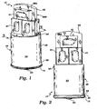
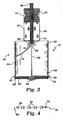
- the LED light bulb 10 has a bulb base 48 that supports at least one LED, preferably a plurality of LEDs 61.
- the bulb base 48 has an electrical contact 50, an outer sidewall 54, and an insulator 52 between the electrical contact 50 and the outer sidewall 54.
- the outer sidewall 54 has an upper edge 56 and a bottom edge 58, and is preferably generally cylindrical in shape.
- the outer sidewall 54 is preferably constructed of an electrically conductive material such as steel.
- the electrical contact 50 is in electrical communication the plurality of LEDs 61, preferably through a first conductor 62 that is electrically connected to a first connection point 64 of the bulb circuit board 66.
- the plurality of LEDs 61 are in electrical communication with the electrical contact 50 through a first resistor 68.
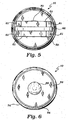
- the plurality of LEDs 61 preferably includes four LEDs that are connected to each other in series.
- the four LEDs 61 are then connected to a second resistor 73, which is then connected to a second connection point 70.
- the second connection point 70 is electrically connected to the outer sidewall 54, preferably through a second conductor 72. While this arrangement is preferred, those skilled in the art can devise other arrangements, and any equivalent arrangements should be considered within the scope of the claimed invention.
- the outer sidewall 54 includes a flange 74 extending outwardly from near the bottom edge 58 of the outer sidewall 54.
- the flange 74 may be integral with or otherwise attached to the outer sidewall 54, and is adapted to removably engage the LED light strip 12, as described in greater detail below, for removably mounting the LED light bulb 10 on the LED light strip 12.
- the bulb circuit board 66 is preferably mounted upon the bulb base 48 such that it extends upwardly therefrom.
- the bulb circuit board 66 preferably has a first side 66A and a second side 66B.
- Each of the sides 66A and 66B is adapted to mount some of the plurality of LEDs 61, preferably three LEDs on each side.
- the bulb circuit board 66 is preferably inserted into the bulb base 48 such that it frictionally engages the upper edge 56 of the outer sidewall 54.
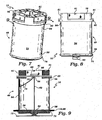
- the LED light bulb 10 may include a rigid tray 60 affixed to a upper edge 56 of the outer sidewall 54.
- the rigid tray 60 is constructed of a strong, rigid, and durable material and is adapted to mount the bulb circuit board 66 across the upper edge 56 of the outer sidewall 54 so that the bulb circuit board 66 covers the bulb base 48.
- the LED light bulb 10 may include four LEDs -61 mounted on the bulb circuit board 66 and disposed in a generally rectangular arrangement on a bulb circuit board 66 around the first and second resistors 68 and 73.
- the rigid tray 60 may include a plurality of studs 76 extending upwardly from the rigid tray 60. Each of the plurality of studs 76 is positioned between two of the plurality of LEDs 61, and extends upwardly above the bulb circuit board 66 to approximately the same height as the plurality of LEDs 61.
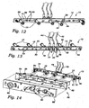
- the plurality of LED light bulbs 10 are adapted to be used in conjunction with the LED light strip 12 shown in FIGS. 12-15.
- the LED light strip 12 includes a printed circuit board assembly that includes a means for removably attaching the plurality of LED light bulbs 10.
- the printed circuit board assembly includes a printed circuit board 14, and the means for removably attaching includes a plurality of locking clips 16 that function to hold the plurality of the LED light bulbs 10 operably on the printed circuit board 14.
- the printed circuit board 14 of the LED light strip 12 has a front surface 18 and an opposing rear surface 20.
- a plurality of anode contacts 22 are disposed on the printed circuit board 14, preferably on the front surface 18.
- the printed circuit board 14 is an elongate shape and the plurality of anode contacts 22 are evenly spaced down the length of the printed circuit board 14; however, the printed circuit board 14 could be adapted to various alternative uses which would dictate alternative sizes and shapes.
- the printed circuit board 14 also includes a plurality of cathode contacts 24, each of the plurality of cathode contacts 24 being positioned in proximity to one of the plurality of anode contacts 22.
- each of the plurality of locking clips 16 is attached to one of the plurality of cathode contacts 24, and each of the plurality of locking clips 16 is adapted to removably engage one of the plurality of LED bulbs 10.
- Each of the plurality of locking clips 16 preferably has a clip base 26 that extends to a forked end 28 and is constructed of an electrically conductive material.
- each of the plurality of locking clips 16 is constructed of a resilient material such as spring steel so that each of the plurality of locking clips 16 can function to clamp one of the plurality of LED light bulbs 10 against the printed circuit board 14.
- the clip base 26 of each of the plurality of locking clips 16 is fastened to the printed circuit board 14 and electronically connected to one of the plurality of cathode contacts 24 such that the forked end 28 is positioned over one of the plurality of anode contacts 22.
- the clip base 26 is fastened to the printed circuit board 14 with a fastener such as a rivet 30 or similar fastening device.
- the printed circuit board 14 includes an anode connection point 32 and a cathode connection point 34 to enable the printed circuit board 14 to be electrically connected to an outside power source (not shown).
- the anode connection point 32 is electrically connected to each of the plurality of anode contacts 22 through an anode bus 38.
- the cathode connection point 34 is electrically connected to each of the plurality of cathode contacts 24 through a cathode bus 40.
- the ground connection point 36 is electrically connected to a ground wire 46 for grounding the LED light strip 12.
- An anode wire 42 is connectable to the anode connection point 32 for connecting the LED light strip 12 to the power source (not shown).
- a cathode wire 44 is connectable to the cathode connection point 34 for connecting the LED light strip 12 to another LED light strip 12, if more than one of the LED light strips 12 are being used in series.
- the printed circuit board 14 also includes a ground connection point 36.
- a ground wire 46 is connectable to the ground connection point 36 for grounding the LED light strip 12. While the present embodiment illustrates a single series of LED light bulbs 10 being connected to the printed circuit board 14, the printed circuit board 14 could include two or more sets connected in series, or any other arrangement that could be devised by those skilled in the art. Since the general construction of the printed circuit board 14 is well known to those skilled in the art, it is not described in greater detail herein.
- the plurality of the LED light bulbs 10 may be removably fastened to the LED light strip 12 using the plurality of locking clips 16.
- the forked end 28 of one of the plurality of locking clips 16 is adapted to fit over the flange 74 and lock around the outer sidewall 54 of one of the plurality of LED bulbs 10, thereby forming an electrical connection between the locking clip 16 and the outer sidewall 54.
- the plurality of locking clips 16 also function to bias each of the plurality of LED light bulbs 10 against one of the plurality of anode contacts 22.
- the LED light strip 12 is preferably used in conjunction with a sign 78 that includes at least one translucent portion 80.
- the sign 78 includes a no-smoking sign such as is typically used in airplanes.
- the no-smoking sign 78 includes a base unit 82 having a plurality of recesses 84 that each include one of a plurality of bulb apertures 86.
- Each of the plurality of bulb apertures 86 is shaped, spaced, and otherwise adapted to receive one of the plurality of LED light bulbs 10 mounted upon the printed circuit board 14 of the LED light strip 12.
- the no-smoking sign 78 further includes a cover plate 88 that is adapted to attach to the base unit 82 to cover the plurality of recesses 84.
- the cover plate 88 has the at least one translucent portion 80 that enables light from the plurality of LED light bulbs 10 to shine through and thereby form a lighted signal.
- the no-smoking sign 78 further includes a means for fastening the LED light strip 12 securely to the base unit 82 of the no-smoking sign 78.
- the means for fastening may be a pair of screws 90 in one embodiment; however, any similar fastener or equivalent should be considered within the scope of the claimed invention.
- at least one of the plurality of LEDs 61 may be a colored LED, so that the at least one translucent portion 80 may be clear or at least uncolored and still provide a colored signal. It is common, for example, that the signal should be red or another color, and this can be provided by using LEDs that are red. This is not possible using ordinary incandescent bulbs, which require a colored filter to provide the sign 78 with a colored output.
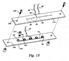
- the printed circuit board assembly includes a first circuit board 102 and a second circuit board 110.
- the means for removably attaching includes a plurality of bulb apertures 104 through the first circuit board 102.
- the plurality of anode contacts 22 are provided on the second circuit board 110, as is the anode bus 38 and the anode connection point 32 for the anode wire 42.
- the plurality of cathode contacts 24 are printed upon the first circuit board 102 adjacent each of the plurality of bulb apertures 104 and connected by the cathode bus 40 with the cathode connection point 34 and the cathode wire 44.
Landscapes
- Engineering & Computer Science (AREA)
- General Engineering & Computer Science (AREA)
- Physics & Mathematics (AREA)
- Microelectronics & Electronic Packaging (AREA)
- Optics & Photonics (AREA)
- Aviation & Aerospace Engineering (AREA)
- Non-Portable Lighting Devices Or Systems Thereof (AREA)
- Illuminated Signs And Luminous Advertising (AREA)
- Fastening Of Light Sources Or Lamp Holders (AREA)
Priority Applications (1)
| Application Number | Priority Date | Filing Date | Title |
|---|---|---|---|
| EP04075390A EP1484547A3 (de) | 2003-06-02 | 2004-02-09 | LED-Lampe für eine Lichtanzeige in einem Flugzeug |
Applications Claiming Priority (3)
| Application Number | Priority Date | Filing Date | Title |
|---|---|---|---|
| US452107 | 2003-06-02 | ||
| US10/452,107 US6886963B2 (en) | 2002-06-21 | 2003-06-02 | LED light bulb for use in an illuminated aircraft sign |
| EP04075390A EP1484547A3 (de) | 2003-06-02 | 2004-02-09 | LED-Lampe für eine Lichtanzeige in einem Flugzeug |
Publications (2)
| Publication Number | Publication Date |
|---|---|
| EP1484547A2 true EP1484547A2 (de) | 2004-12-08 |
| EP1484547A3 EP1484547A3 (de) | 2006-08-16 |
Family
ID=33159492
Family Applications (1)
| Application Number | Title | Priority Date | Filing Date |
|---|---|---|---|
| EP04075390A Withdrawn EP1484547A3 (de) | 2003-06-02 | 2004-02-09 | LED-Lampe für eine Lichtanzeige in einem Flugzeug |
Country Status (1)
| Country | Link |
|---|---|
| EP (1) | EP1484547A3 (de) |
Cited By (4)
| Publication number | Priority date | Publication date | Assignee | Title |
|---|---|---|---|---|
| WO2012020119A1 (de) * | 2010-08-13 | 2012-02-16 | Siteco Beleuchtungstechnik Gmbh | Rückseitige anbindung von led-modulen |
| CN103411170A (zh) * | 2013-08-21 | 2013-11-27 | 东莞市精航科技有限公司 | 一种用于飞机上的led航空指示灯及其制作方法 |
| US8912733B2 (en) | 2013-05-04 | 2014-12-16 | Vizio, Inc. | Light bulb and florescent tube replacement using FIPEL panels |
| GB2631074A (en) * | 2023-04-18 | 2024-12-25 | Apios Ltd | Seat power supply and display system |
Citations (7)
| Publication number | Priority date | Publication date | Assignee | Title |
|---|---|---|---|---|
| US4772869A (en) | 1987-02-24 | 1988-09-20 | Lamba Systems, Inc. | Communication apparatus |
| US5151679A (en) | 1988-03-31 | 1992-09-29 | Frederick Dimmick | Display sign |
| USD331980S (en) | 1990-05-23 | 1992-12-22 | Peter Henderson | Combined illuminated sign and control housing for vehicles |
| US5647658A (en) | 1995-05-11 | 1997-07-15 | Ziadi; Bouchaib | Fiber-optic lighting system |
| US5842297A (en) | 1997-02-04 | 1998-12-01 | Flying Dragons Co. Ltd. | Luminant sign |
| US5964051A (en) | 1997-03-03 | 1999-10-12 | Autronics Plastics, Inc. | Internally illuminated sign |
| US6283612B1 (en) | 2000-03-13 | 2001-09-04 | Mark A. Hunter | Light emitting diode light strip |
Family Cites Families (2)
| Publication number | Priority date | Publication date | Assignee | Title |
|---|---|---|---|---|
| US5806965A (en) * | 1996-01-30 | 1998-09-15 | R&M Deese, Inc. | LED beacon light |
| US6886963B2 (en) * | 2002-06-21 | 2005-05-03 | Pervaiz Lodhie | LED light bulb for use in an illuminated aircraft sign |
-
2004
- 2004-02-09 EP EP04075390A patent/EP1484547A3/de not_active Withdrawn
Patent Citations (7)
| Publication number | Priority date | Publication date | Assignee | Title |
|---|---|---|---|---|
| US4772869A (en) | 1987-02-24 | 1988-09-20 | Lamba Systems, Inc. | Communication apparatus |
| US5151679A (en) | 1988-03-31 | 1992-09-29 | Frederick Dimmick | Display sign |
| USD331980S (en) | 1990-05-23 | 1992-12-22 | Peter Henderson | Combined illuminated sign and control housing for vehicles |
| US5647658A (en) | 1995-05-11 | 1997-07-15 | Ziadi; Bouchaib | Fiber-optic lighting system |
| US5842297A (en) | 1997-02-04 | 1998-12-01 | Flying Dragons Co. Ltd. | Luminant sign |
| US5964051A (en) | 1997-03-03 | 1999-10-12 | Autronics Plastics, Inc. | Internally illuminated sign |
| US6283612B1 (en) | 2000-03-13 | 2001-09-04 | Mark A. Hunter | Light emitting diode light strip |
Cited By (6)
| Publication number | Priority date | Publication date | Assignee | Title |
|---|---|---|---|---|
| WO2012020119A1 (de) * | 2010-08-13 | 2012-02-16 | Siteco Beleuchtungstechnik Gmbh | Rückseitige anbindung von led-modulen |
| US8912733B2 (en) | 2013-05-04 | 2014-12-16 | Vizio, Inc. | Light bulb and florescent tube replacement using FIPEL panels |
| US9497823B2 (en) | 2013-05-04 | 2016-11-15 | Vizio, Inc | Light bulb and florescent tube replacement using FIPEL panels |
| CN103411170A (zh) * | 2013-08-21 | 2013-11-27 | 东莞市精航科技有限公司 | 一种用于飞机上的led航空指示灯及其制作方法 |
| CN103411170B (zh) * | 2013-08-21 | 2015-12-09 | 东莞市精航科技有限公司 | 一种用于飞机上的led航空指示灯的制作方法 |
| GB2631074A (en) * | 2023-04-18 | 2024-12-25 | Apios Ltd | Seat power supply and display system |
Also Published As
| Publication number | Publication date |
|---|---|
| EP1484547A3 (de) | 2006-08-16 |
Similar Documents
| Publication | Publication Date | Title |
|---|---|---|
| US6886963B2 (en) | LED light bulb for use in an illuminated aircraft sign | |
| US6598996B1 (en) | LED light bulb | |
| US6414801B1 (en) | Catadioptric light emitting diode assembly | |
| US5506760A (en) | Light fitting unit for illuminated signs | |
| US6568833B2 (en) | Light | |
| US6179431B1 (en) | Flashlight with electro-luminescent element | |
| US6450661B1 (en) | Light source device using light emitting diode and light emitting device using same | |
| US8876331B2 (en) | Annular lighting fixture and method for illumination | |
| US20070153518A1 (en) | LED bulb | |
| US6942354B2 (en) | Lighting system and housing therefore | |
| US8235569B2 (en) | Light assembly for a vehicle | |
| US5667293A (en) | Flashlight with illumination and alerting effect | |
| US6565244B1 (en) | Single source identification light bar | |
| US6190027B1 (en) | Electroluminescent courtesy light with optical element and tube for running board of vehicle | |
| CA2611423A1 (en) | Illuminated display system for a vehicle | |
| US6550950B1 (en) | Light emitting diodes vehicle lamp | |
| EP1484547A2 (de) | LED-Lampe für eine Lichtanzeige in einem Flugzeug | |
| JPH0222508U (de) | ||
| JP3574614B2 (ja) | 発光体及び灯器 | |
| US7753540B2 (en) | Illuminable indicator and light engine therefor | |
| JP2000200512A (ja) | Ledランプ | |
| US8956030B1 (en) | Automotive bulbs having LEDs pointing in different directions | |
| JP3108784B2 (ja) | 警告用表示装置 | |
| CN1104729C (zh) | 具有发光二极管的信号装置 | |
| JPH0669985U (ja) | 発光表示器 |
Legal Events
| Date | Code | Title | Description |
|---|---|---|---|
| PUAI | Public reference made under article 153(3) epc to a published international application that has entered the european phase |
Free format text: ORIGINAL CODE: 0009012 |
|
| AK | Designated contracting states |
Kind code of ref document: A2 Designated state(s): AT BE BG CH CY CZ DE DK EE ES FI FR GB GR HU IE IT LI LU MC NL PT RO SE SI SK TR |
|
| AX | Request for extension of the european patent |
Extension state: AL LT LV MK |
|
| PUAL | Search report despatched |
Free format text: ORIGINAL CODE: 0009013 |
|
| AK | Designated contracting states |
Kind code of ref document: A3 Designated state(s): AT BE BG CH CY CZ DE DK EE ES FI FR GB GR HU IE IT LI LU MC NL PT RO SE SI SK TR |
|
| AX | Request for extension of the european patent |
Extension state: AL LT LV MK |
|
| 17P | Request for examination filed |
Effective date: 20070216 |
|
| STAA | Information on the status of an ep patent application or granted ep patent |
Free format text: STATUS: THE APPLICATION HAS BEEN WITHDRAWN |
|
| AKX | Designation fees paid |
Designated state(s): AT BE BG CH CY CZ DE DK EE ES FI FR GB GR HU IE IT LI LU MC NL PT RO SE SI SK TR |
|
| 18W | Application withdrawn |
Effective date: 20070328 |