EP1484583A1 - Dispositif et procédé de mesure de la vitesse d'un écoulement et ses applications pour la mesure du flux thermique et de la vitesse du vent et/ou la direction du vent - Google Patents
Dispositif et procédé de mesure de la vitesse d'un écoulement et ses applications pour la mesure du flux thermique et de la vitesse du vent et/ou la direction du vent Download PDFInfo
- Publication number
- EP1484583A1 EP1484583A1 EP04102077A EP04102077A EP1484583A1 EP 1484583 A1 EP1484583 A1 EP 1484583A1 EP 04102077 A EP04102077 A EP 04102077A EP 04102077 A EP04102077 A EP 04102077A EP 1484583 A1 EP1484583 A1 EP 1484583A1
- Authority
- EP
- European Patent Office
- Prior art keywords
- ducts
- pair
- measurement
- flowing fluid
- flow velocity
- Prior art date
- Legal status (The legal status is an assumption and is not a legal conclusion. Google has not performed a legal analysis and makes no representation as to the accuracy of the status listed.)
- Withdrawn
Links
- 238000000691 measurement method Methods 0.000 title 1
- 239000012530 fluid Substances 0.000 claims abstract description 83
- 238000005259 measurement Methods 0.000 claims abstract description 38
- 238000000034 method Methods 0.000 claims abstract description 18
- 238000010438 heat treatment Methods 0.000 claims abstract description 14
- 230000017525 heat dissipation Effects 0.000 claims abstract description 8
- 238000001816 cooling Methods 0.000 claims description 6
- 238000009529 body temperature measurement Methods 0.000 claims 1
- 238000004378 air conditioning Methods 0.000 abstract description 8
- 238000010586 diagram Methods 0.000 description 10
- 238000010276 construction Methods 0.000 description 5
- 238000012545 processing Methods 0.000 description 5
- 238000012544 monitoring process Methods 0.000 description 4
- 238000012423 maintenance Methods 0.000 description 3
- XLYOFNOQVPJJNP-UHFFFAOYSA-N water Substances O XLYOFNOQVPJJNP-UHFFFAOYSA-N 0.000 description 2
- 230000032683 aging Effects 0.000 description 1
- JRPBQTZRNDNNOP-UHFFFAOYSA-N barium titanate Chemical compound [Ba+2].[Ba+2].[O-][Ti]([O-])([O-])[O-] JRPBQTZRNDNNOP-UHFFFAOYSA-N 0.000 description 1
- 229910002113 barium titanate Inorganic materials 0.000 description 1
- 230000005494 condensation Effects 0.000 description 1
- 238000009833 condensation Methods 0.000 description 1
- 238000005260 corrosion Methods 0.000 description 1
- 230000007797 corrosion Effects 0.000 description 1
- 230000003247 decreasing effect Effects 0.000 description 1
- 238000013461 design Methods 0.000 description 1
- 239000000428 dust Substances 0.000 description 1
- 230000000694 effects Effects 0.000 description 1
- 238000001704 evaporation Methods 0.000 description 1
- 230000008020 evaporation Effects 0.000 description 1
- 238000004880 explosion Methods 0.000 description 1
- 239000007788 liquid Substances 0.000 description 1
- 239000000463 material Substances 0.000 description 1
- 238000012986 modification Methods 0.000 description 1
- 230000004048 modification Effects 0.000 description 1
- 238000011084 recovery Methods 0.000 description 1
- 239000002918 waste heat Substances 0.000 description 1
Images


Classifications
-
- G—PHYSICS
- G01—MEASURING; TESTING
- G01F—MEASURING VOLUME, VOLUME FLOW, MASS FLOW OR LIQUID LEVEL; METERING BY VOLUME
- G01F1/00—Measuring the volume flow or mass flow of fluid or fluent solid material wherein the fluid passes through a meter in a continuous flow
- G01F1/68—Measuring the volume flow or mass flow of fluid or fluent solid material wherein the fluid passes through a meter in a continuous flow by using thermal effects
- G01F1/684—Structural arrangements; Mounting of elements, e.g. in relation to fluid flow
- G01F1/688—Structural arrangements; Mounting of elements, e.g. in relation to fluid flow using a particular type of heating, cooling or sensing element
- G01F1/69—Structural arrangements; Mounting of elements, e.g. in relation to fluid flow using a particular type of heating, cooling or sensing element of resistive type
- G01F1/692—Thin-film arrangements
-
- G—PHYSICS
- G01—MEASURING; TESTING
- G01F—MEASURING VOLUME, VOLUME FLOW, MASS FLOW OR LIQUID LEVEL; METERING BY VOLUME
- G01F1/00—Measuring the volume flow or mass flow of fluid or fluent solid material wherein the fluid passes through a meter in a continuous flow
- G01F1/68—Measuring the volume flow or mass flow of fluid or fluent solid material wherein the fluid passes through a meter in a continuous flow by using thermal effects
- G01F1/684—Structural arrangements; Mounting of elements, e.g. in relation to fluid flow
- G01F1/688—Structural arrangements; Mounting of elements, e.g. in relation to fluid flow using a particular type of heating, cooling or sensing element
- G01F1/69—Structural arrangements; Mounting of elements, e.g. in relation to fluid flow using a particular type of heating, cooling or sensing element of resistive type
-
- G—PHYSICS
- G01—MEASURING; TESTING
- G01K—MEASURING TEMPERATURE; MEASURING QUANTITY OF HEAT; THERMALLY-SENSITIVE ELEMENTS NOT OTHERWISE PROVIDED FOR
- G01K17/00—Measuring quantity of heat
- G01K17/06—Measuring quantity of heat conveyed by flowing media, e.g. in heating systems e.g. the quantity of heat in a transporting medium, delivered to or consumed in an expenditure device
- G01K17/08—Measuring quantity of heat conveyed by flowing media, e.g. in heating systems e.g. the quantity of heat in a transporting medium, delivered to or consumed in an expenditure device based upon measurement of temperature difference or of a temperature
- G01K17/10—Measuring quantity of heat conveyed by flowing media, e.g. in heating systems e.g. the quantity of heat in a transporting medium, delivered to or consumed in an expenditure device based upon measurement of temperature difference or of a temperature between an inlet and an outlet point, combined with measurement of rate of flow of the medium if such, by integration during a certain time-interval
- G01K17/12—Indicating product of flow and temperature difference directly or temperature
- G01K17/16—Indicating product of flow and temperature difference directly or temperature using electrical or magnetic means for both measurements
-
- G—PHYSICS
- G01—MEASURING; TESTING
- G01P—MEASURING LINEAR OR ANGULAR SPEED, ACCELERATION, DECELERATION, OR SHOCK; INDICATING PRESENCE, ABSENCE, OR DIRECTION, OF MOVEMENT
- G01P13/00—Indicating or recording presence, absence, or direction, of movement
- G01P13/02—Indicating direction only, e.g. by weather vane
-
- G—PHYSICS
- G01—MEASURING; TESTING
- G01P—MEASURING LINEAR OR ANGULAR SPEED, ACCELERATION, DECELERATION, OR SHOCK; INDICATING PRESENCE, ABSENCE, OR DIRECTION, OF MOVEMENT
- G01P5/00—Measuring speed of fluids, e.g. of air stream; Measuring speed of bodies relative to fluids, e.g. of ship, of aircraft
- G01P5/10—Measuring speed of fluids, e.g. of air stream; Measuring speed of bodies relative to fluids, e.g. of ship, of aircraft by measuring thermal variables
- G01P5/12—Measuring speed of fluids, e.g. of air stream; Measuring speed of bodies relative to fluids, e.g. of ship, of aircraft by measuring thermal variables using variation of resistance of a heated conductor
Definitions
- the present invention relates to a method and apparatus for measuring flow velocity of a fluid.
- the invention is particularly useful in various types of systems including: a system for measuring heat flow; an anemometer for measuring wind velocity and direction; and a wind tunnel for measuring wind velocity.
- the invention is therefore described below with respect to the above applications, but it will be appreciated that the invention can advantageously be used in other applications as well.
- heat flow i.e., heat taken from or added to a system.
- examples of the above include hot-water heating systems, air conditioning systems, heat exchangers, waste-heat recovery units, de-super heaters, and solar heating systems.
- the electrical energy consumed in generating the heat added to the working fluid, or in extracting the heat from the working fluid cannot be conveniently distinguished for cost-allocation or billing purposes from the electrical energy consumed for other uses, e.g., for lighting, operating machines, etc. There is therefore a need for a simple, efficient and inexpensive system for measuring heat flow directly.
- anemometer for measuring the velocity and direction of the wind.
- the anemometers commonly used today for this purpose generally include mechanically moving parts which are prone to errors, particularly during long periods of operation, because of soiling by dust transported with the air and failure of electric components by aging. Similar drawbacks are involved in measuring the velocity of the wind in wind tunnels. Therefore, there is also a need for a simple, efficient and inexpensive system for measuring wind velocity and/or wind direction in an anemometer or wind tunnel.
- An object of the present invention is to provide a method and apparatus having advantages in one or more of the above respects for measuring fluid-flow velocity, particularly useful in measuring heat flow in a heating or cooling system, wind velocity and direction in an anemometer, and/or flow velocity in a wind tunnel.
- a method of measuring the flow velocity of a flowing fluid comprising: immersing within the flowing fluid a thermistor having a resistance varying with temperature; applying electrical current through the thermistor to heat it to, and to maintain it at, a predetermined temperature above that of the flowing fluid; producing a measurement of the electrical current through the thermistor while maintained at the predetermined temperature, thereby providing a measurement of the rate of heat dissipation of the thermistor produced by the flowing fluid in which the thermistor is immersed; and utilizing the measurement of electrical current to produce a measurement of the flow velocity of the flowing fluid; characterized in that the electrical resistor is a positive temperature coefficient thermistor driven by a constant voltage source and having a resistance which increases sharply at said predetermined temperature, such that the thermistor is automatically self-controlled to substantially maintain the predetermined temperature, whereby the electrical current drawn by the thermistor is a measurement of the thermal load on the thermistor resulting from the
- the flowing fluid in which the thermistor is immersed is a working fluid in a heat flow system in which the working fluid has an initial temperature at the inlet to the system and a final temperature at the outlet from the system.
- the initial temperature and the final temperature of the working fluid are also measured and utilized with the flow velocity measurement to produce a measurement of the rate of heat flow in the system.
- the heat flow system is a centralized heating or cooling system for supplying heated or cooled air to a plurality of utilization units.
- the flow velocity, initial temperature, and final temperature of the working fluid supplied to each of the utilization units are measured and utilized to produce a measurement of the rate of heat flow in each of the utilization units.
- each of the utilization units is an apartment unit to be heated or cooled; and in another described embodiment, each of the utilization units is a workpiece processing unit utilizing heat or cold during a workpiece treating process.
- the velocity of the flowing fluid is measured along each of two non-parallel axes to produce a measurement of both the flow velocity and the flow direction of the flowing fluid.
- the flowing fluid is the wind
- the flow velocity of the wind is measured in a duct system including at least two ducts aligned along axes at an angle to each other. More particularly, the described duct system includes a first pair of ducts along a first axis, and a second pair of ducts along a second axis orthogonal to the first axis.
- the ducts of each of pair are located side-by-side along parallel axes.
- Each of the ducts is tapered from a large-diameter at one end to a small-diameter at the opposite end.
- the ducts of each pair are oppositely disposed such that each end of each pair of ducts includes the large-diameter end of one duct of the pair, and the small-diameter end of the other duct of the pair.
- the ducts of the first pair are coaxially aligned with each other along the first axis
- the ducts of the second pair are coaxially aligned with each other along the second axis orthogonal to the first axis.
- the invention also provides various types of apparatus operating in accordance with the foregoing method.
- such method and apparatus can be implemented in relatively simple, inexpensive and efficient systems for making various measurements involving fluid flow velocity, including: heat flow in heating and air-conditioning systems: wind velocity and direction in anemometers, and wind velocity in wind tunnels.
- heat flow in heating and air-conditioning systems including: wind velocity and direction in anemometers, and wind velocity in wind tunnels.
- Fig. 1 is a block diagram illustrating a system for monitoring heat flow, i.e., the quantity of heat added to or taken from a fluid, in accordance with the present invention.
- heat flow monitoring systems commonly called BTU measuring systems, are useful in measuring heat flow in heating systems, air conditioning systems, heat-exchanger systems, and the like, for cost allocation or billing purposes.
- the system illustrated in Fig. 1 includes a boiler or chiller 2 supplying heat or cold to a heat utilization system 3 via a working fluid.
- the working fluid flows through a supply duct 4 from the boiler or chiller 2 to the heat utilization system 3, and through a return duct 5 back to the boiler or chiller.
- the supply duct 4 includes a flow sensor FS which senses the flow rate of the working fluid therethrough, and a temperature sensor TS 1 for sensing the initial temperature of the working fluid flowing therethrough to the utilization system 3.
- the return duct 5 also includes a temperature sensor TS 2 for sensing the final temperature of the working fluid as it is returned from the utilization system 3 to the boiler or chiller.
- the rate of heat flow is measured in a simple, inexpensive and efficient manner by the positive temperature coefficient thermistor FS, and the two temperature sensors TS 1 and TS 2 , as described more particularly below.
- the two temperature sensors TS 1 and TS 2 are preferably negative temperature coefficient (NTC) thermistors. Such thermistors have a resistance decreasing substantially linearly with temperature, thereby producing an electrical output signal increasing substantially linearly with temperature.
- Flow sensor FS is a positive temperature coefficient (PTC) thermistor.
- PTC positive temperature coefficient
- Such a thermistor has a resistance which, at a particular temperature, increases sharply with respect to temperature so as to automatically operate substantially at a predetermined maximum temperature. Thus, when the thermistor is operating at the predetermined maximum temperature, it produces a current flow through the thermistor directly related to the thermal load on the thermistor.
- PTC thermistor FS serving as the flow sensor, is powered by a power supply 6 which applies electrical current through the thermistor to heat it to a predetermined temperature above that of the working fluid in the supply duct 4 as measured by temperature sensor TS 1 .
- the predetermined temperature (above that of the working fluid) is the temperature at which the resistance of the PTC thermistor FS increases sharply.
- Fig. 2 includes curves illustrating the temperature-resistance relationship of three typical PTC thermistors, wherein it will be seen that at a predetermined temperature, depending on the composition of the thermistor, the resistance increases sharply virtually to infinity. Accordingly, such a thermistor supplied by acoustical voltage source automatically self-regulates itself, without any feedback controls, so as to maintain the desired predetermined temperature above the temperature of the working fluid in the supply duct 4. Since the temperature remains constant, the current through the thermistor therefore varies in accordance with the thermal load on the thermistor. This thermal load in turn varies with the rate that heat of the thermistor is dissipated by the flowing working fluid, and thereby, with the flow velocity of the working fluid.
- the PTC thermistor of the leftmost curve in Fig. 2 could be used, in which case the predetermined temperature to which the thermistor would be healed would be about 130°C.
- the electrical current through thermistor FS is measured by current meter 7 which outputs an electrical signal serving as one input to a processor 8.
- Processor 8 includes a second input from temperature sensor TS 1 corresponding to the temperature of the working fluid flowing through the supply duct 4.
- Processor 8 includes a third input from temperature sensor TS 2 corresponding to the temperature of the working fluid through the return duct 5.
- the foregoing inputs are processed by processor 8 which produces an output at 9a representing the heat flow rate, and another output at 9b representing the total heat flow over a predetermined time interval.
- the two outputs may be recorded and used for billing purposes, cost-allocating purposes, and the like, and may also be displayed in displays 9c and 9d, respectively.
- a preferred PTC thermistor that may be used for flow sensor FS is one made of barium titanate since this material is characterized by a very high resistance to corrosion and a relatively low hazard to explosion.
- Fig. 3 is a block diagram illustrating the above-described heat-flow system implemented in a centralized heating or cooling system for supplying heated or cooled air to a plurality of utilization devices, in this case apartment units.
- the centralized system illustrated in Fig. 3 includes a boiler or chiller 12 for supplying heated or cooled air to a plurality of apartment units, indicated at 13a ---- 13n, via a working fluid circulated to the apartment units by a supply duct 14, and returned to the boiler or chiller via a return duct 15.
- the apartment units 13a ---- 13n are in parallel branches between the supply duct 14 and the return duct 15.
- Each branch includes a flow sensor FS for sensing the rate of flow of the working fluid through the respective branch, a temperature sensor TS 1 for sensing the initial temperature of the working fluid at the inlet to the respective apartment unit, and a temperature sensor TS 2 for sensing the final temperature of the working fluid at the outlet of the apartment unit before returned to the boiler or chiller via the return duct 15.
- a flow sensor FS for sensing the rate of flow of the working fluid through the respective branch
- a temperature sensor TS 1 for sensing the initial temperature of the working fluid at the inlet to the respective apartment unit
- a temperature sensor TS 2 for sensing the final temperature of the working fluid at the outlet of the apartment unit before returned to the boiler or chiller via the return duct 15.
- the flow sensor FS in the respective branch is a positive temperature coefficient (PTC) thermistor for measuring the flow velocity of the working fluid through the respective branch; whereas the two temperature sensors TS 1 , TS 2 are negative temperature coefficient (NTC) thermistors for measuring the initial temperature and final temperature, respectively, of the working fluid in the respective branch.
- PTC positive temperature coefficient
- NTC negative temperature coefficient
- each of the branches is provided with a processor 18a - 18n, connected to receive the outputs of the flow sensor FS and the temperature sensors TS 1 , TS 2 , in the respective branch, and to compute therefrom a measurement of the rate of heat flow in the respective branch, as well as the total heat flow therein for the respective time period.
- a processor 18a - 18n connected to receive the outputs of the flow sensor FS and the temperature sensors TS 1 , TS 2 , in the respective branch, and to compute therefrom a measurement of the rate of heat flow in the respective branch, as well as the total heat flow therein for the respective time period.
- Fig. 4 illustrates a centralized heating or cooling system for supplying heated or cooled air to a plurality of utilization units in the form of workpiece processing units, shown at 23a - 23n, each of which utilizes heat or cold during a workpiece treating process.
- the other components of the system illustrated in Fig. 4 are the same as described above with respect to Fig. 3, and therefore the same reference numerals have been used to identify the corresponding components.
- Figs. 5 - 7 illustrate the invention implemented in an anemometer, for measuring the flow velocity and direction of the wind.
- anemometer for measuring the flow velocity and direction of the wind.
- Fig. 5 pictorially illustrates one construction of an anemometer in accordance with the present invention
- Fig. 6 is a block diagram illustrating the electrical system in the anemometer of Fig. 5.
- the anemometer illustrated in Fig. 5 includes a duct system having a first pair of ducts 31, 32 along a first axis X, and a second pair of ducts 33, 34 along a second axis Y orthogonal to the first axis.
- the ducts of each pair are located side-by-side along parallel axes. That is, the axis of duct 31 is at the side of and parallel to the axis of duct 32, both axes being parallel to the X-axis of the duct pair 31, 32; similarly, the axis of duct 33 is at the side of and parallel to the axis of duct 34, both axes of this pair being parallel to the Y-axis.
- each of the ducts is tapered from a large-diameter at one end to a small-diameter at the opposite end.
- the two ducts of each pair are oppositely disposed such that each end of each pair of ducts includes the large-diameter end of one duct of the pair, and the small-diameter end of the other duct of the pair.
- the large-diameter end 31a of duct 31 and the small-diameter end 32b of duct 32 are at one end of the duct pair 31, 32; whereas the opposite end of that duct pair includes the small-diameter end 31b of duct 31 and the large-diameter end 32a of duct 32.
- the large-diameter end 33a of duct 33 and the small-diameter end 34b of duct 34 are at one end of duct pair 33, 34; whereas the small-diameter end 33b of duct 33 and the large-diameter end 34a of duct 34 are at the opposite end of the duct pair.
- Each of the ducts 31 - 34 includes a flow sensor FS 1 - FS 4 for sensing the rate of flow of the fluid (wind) through the respective duct.
- the flow sensors FS 1 - FS 4 are preferably in the large-diameter end of the respective duct since this location of the flow sensor minimizes the effect of its presence on the component of the wind intercepted by, and flowing through, the respective duct.
- Each of the flow sensors FS 1 - FS 4 is a positive temperature coefficient (PTC) thermistor as described above, such that the electrical current through it is a measurement of the thermal load on the respective thermistor, and thereby a measurement of the wind velocity at the respective end of the respective duct.
- PTC positive temperature coefficient
- Fig. 6 is a block diagram illustrating the electrical system in the anemometer construction of Fig. 5, to produce electrical outputs corresponding to both the wind velocity and the wind direction.
- the electrical system includes a processor 30 which receives a measurement of the current flow through each of the four flow sensors FS 1 - FS 4 . Since the specific orientation of the two pairs of ducts 31, 32 and 33, 34, respectively, are known with respect to the two orthogonal axes X, Y, and also with respect to each other, the information inputted by the flow sensors FS 1 - FS 4 is sufficient to enable the processor 30 to compute both the wind velocity and the wind direction. This information is outputted via displays 31, 32.
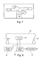
- Fig. 7 illustrates another anemometer construction in accordance with the present invention and also including a first pair of ducts 41, 42, aligned along one axis (e.g., the X-axis) and a second pair of ducts 43, 44 aligned along the other orthogonal axis (e.g., the Y-axis).
- the two ducts of each pair are coaxially aligned with each other along their respective axes.
- ducts 41 and 42 have a common axis which is coaxial with the X-axis; and ducts 43, 44 also have a common axis, which is coaxial with the Y-axis.
- each of the ducts has an outer end 41a - 44a exposed to the wind, and an inner end 41b - 44b angularly displaced with respect to its outer end for mounting the ducts within a mounting member 45.
- the outer ends 41a - 44a of each duct exposed to the wind includes a positive temperature coefficient (PTC) thermistor FS serving as the flow sensor for sensing the velocity of the wind intercepted by the respective duct in the manner described above.
- PTC positive temperature coefficient
- Fig. 7 the outer ends of the ducts 41 - 44 are shown as of substantially uniform diameter. It will be appreciated, however, that those ends of the ducts could also be tapered as described above with respect to Fig. 5.
- the block diagram of Fig. 6 described above with respect to Fig. 5 is also applicable with respect to Fig. 7.
- the fluid-flow (wind) monitoring systems illustrated in Figs. 5 - 7 also require no moving parts and substantially no maintenance, and therefore have virtually infinite lifetime.
- the PTC sensor is of such small thermal mass, it has small thermal inertia. This makes such systems particularly useful in measuring gusts, i.e., sudden, strong rushes of air or wind, from other directions than the mainstream.
- the illustrated systems can measure a North-East wind of two nautical miles, and a South-West upper gusts of four nautical miles once every two minutes.
- the output of the system could include not only wind direction and wind speed, but also wind upper gust direction and speed, and further, statistics and periodicity of these upper gusts.
- Fig. 8 illustrates a wind tunnel constructed in accordance with the present invention for measuring the flow velocity of wind through the tunnel.
- the wind tunnel illustrated in Fig. 8 is basically of the same construction as described above with respect to Fig. 1, except that, since it measures only wind velocity and not heat flow, the initial and final temperature sensors (TS 1 , TS 2 in Fig. 1) are not needed.
- the illustrated wind tunnel includes a tunnel or duct 50 having a flow sensor FS therein in the form of a PTC thermistor; a power supply 51 for applying electrical current through the thermistor to heat it to, and to maintain it at, a predetermined temperature above that of the flowing air through the wind tunnel; a current meter 52 for measuring the electrical current through the PTC thermistor FS; and a processor 53 for producing from the measured current a measurement of the flow velocity of the air within the wind tunnel.
- a flow sensor FS in the form of a PTC thermistor
- a power supply 51 for applying electrical current through the thermistor to heat it to, and to maintain it at, a predetermined temperature above that of the flowing air through the wind tunnel
- a current meter 52 for measuring the electrical current through the PTC thermistor FS
- a processor 53 for producing from the measured current a measurement of the flow velocity of the air within the wind tunnel.
- the electrical current through the PTC thermistor FS will vary with the thermal load thereon, and the thermal load will vary with the rate at which heat is dissipated from the thermistor by the flowing air, so that the electrical current through the thermistor will represent a measurement of the flow velocity of the wind through the tunnel.
Landscapes
- Physics & Mathematics (AREA)
- General Physics & Mathematics (AREA)
- Fluid Mechanics (AREA)
- Engineering & Computer Science (AREA)
- Chemical & Material Sciences (AREA)
- Combustion & Propulsion (AREA)
- Aviation & Aerospace Engineering (AREA)
- Indicating Or Recording The Presence, Absence, Or Direction Of Movement (AREA)
Applications Claiming Priority (2)
| Application Number | Priority Date | Filing Date | Title |
|---|---|---|---|
| US47171103P | 2003-05-20 | 2003-05-20 | |
| US471711 | 2003-05-20 |
Publications (1)
| Publication Number | Publication Date |
|---|---|
| EP1484583A1 true EP1484583A1 (fr) | 2004-12-08 |
Family
ID=33435262
Family Applications (1)
| Application Number | Title | Priority Date | Filing Date |
|---|---|---|---|
| EP04102077A Withdrawn EP1484583A1 (fr) | 2003-05-20 | 2004-05-13 | Dispositif et procédé de mesure de la vitesse d'un écoulement et ses applications pour la mesure du flux thermique et de la vitesse du vent et/ou la direction du vent |
Country Status (2)
| Country | Link |
|---|---|
| US (1) | US7036367B2 (fr) |
| EP (1) | EP1484583A1 (fr) |
Cited By (1)
| Publication number | Priority date | Publication date | Assignee | Title |
|---|---|---|---|---|
| WO2009024302A1 (fr) * | 2007-08-17 | 2009-02-26 | Mann + Hummel Innenraumfilter Gmbh & Co. Kg | Procédé pour surveiller l'état de charge d'un système de climatisation d'un véhicule automobile |
Families Citing this family (11)
| Publication number | Priority date | Publication date | Assignee | Title |
|---|---|---|---|---|
| US7347092B1 (en) | 2006-09-28 | 2008-03-25 | Delphi Technologies, Inc. | Apparatus and method for fluid flow measurement |
| US7874724B2 (en) * | 2007-04-11 | 2011-01-25 | Trane International Inc. | Method for sensing the liquid level in a compressor |
| US7874208B2 (en) * | 2007-10-10 | 2011-01-25 | Brooks Instrument, Llc | System for and method of providing a wide-range flow controller |
| US8544320B2 (en) * | 2010-05-18 | 2013-10-01 | Siargo Ltd. | Integrated micromachined wind and gas velocity profiler |
| US9494470B2 (en) | 2014-03-20 | 2016-11-15 | Varian Semiconductor Equipment Associates, Inc. | Thermistor based measurement system |
| ES2578061B1 (es) * | 2015-01-19 | 2017-02-27 | Soler & Palau Research, S.L. | Sensor de caudal de aire para instalaciones de ventilación |
| DE102016101324A1 (de) * | 2016-01-26 | 2017-07-27 | Miele & Cie. Kg | Sensoreinheit und Waschmaschine |
| US10247087B2 (en) * | 2016-04-18 | 2019-04-02 | Faraday & Future Inc. | Liquid temperature sensor |
| CN112834158A (zh) * | 2020-12-30 | 2021-05-25 | 中国航天空气动力技术研究院 | 一种内通道热流面测量方法 |
| CN116008587B (zh) * | 2023-02-10 | 2026-03-31 | 广州医软智能科技有限公司 | 一种管道气体流速的测量方法 |
| CN119716135A (zh) * | 2025-02-14 | 2025-03-28 | 北京鹰卫士信息技术有限公司 | 风向风速测量装置 |
Citations (5)
| Publication number | Priority date | Publication date | Assignee | Title |
|---|---|---|---|---|
| DE2531922A1 (de) * | 1974-07-31 | 1976-02-19 | Setron Erzeugung Elektronische | Elektronisches rechenwerk fuer waermezaehlanlagen |
| US4319483A (en) * | 1980-02-25 | 1982-03-16 | Texas Instruments Incorporated | Method of automated fluid flow measurement |
| US5237867A (en) * | 1990-06-29 | 1993-08-24 | Siemens Automotive L.P. | Thin-film air flow sensor using temperature-biasing resistive element |
| US5710380A (en) * | 1996-06-07 | 1998-01-20 | Talley; Robert Lee | Anemometer |
| EP1045234A1 (fr) * | 1999-04-13 | 2000-10-18 | Viterra Energy Services AG | Méthode pour l'acquisition et l'exploration de valeurs de consumption qui dépendent de la température |
Family Cites Families (4)
| Publication number | Priority date | Publication date | Assignee | Title |
|---|---|---|---|---|
| US5069066A (en) * | 1990-05-10 | 1991-12-03 | Djorup Robert Sonny | Constant temperature anemometer |
| US5112136A (en) * | 1990-09-24 | 1992-05-12 | Kiyoshi Sakuma | Method of and apparatus for measuring thermal conductivity |
| US5335513A (en) * | 1993-01-19 | 1994-08-09 | Parker-Hannifin Corporation | Apparatus and method for detecting characteristics of a working fluid |
| US6509553B2 (en) * | 2000-09-05 | 2003-01-21 | A.T.C.T. Advanced Thermal Chips Technologies Ltd. | Method and apparatus for providing an indication of the composition of a fluid particularly useful in heat pumps and vaporizers |
-
2004
- 2004-05-13 US US10/844,397 patent/US7036367B2/en not_active Expired - Fee Related
- 2004-05-13 EP EP04102077A patent/EP1484583A1/fr not_active Withdrawn
Patent Citations (5)
| Publication number | Priority date | Publication date | Assignee | Title |
|---|---|---|---|---|
| DE2531922A1 (de) * | 1974-07-31 | 1976-02-19 | Setron Erzeugung Elektronische | Elektronisches rechenwerk fuer waermezaehlanlagen |
| US4319483A (en) * | 1980-02-25 | 1982-03-16 | Texas Instruments Incorporated | Method of automated fluid flow measurement |
| US5237867A (en) * | 1990-06-29 | 1993-08-24 | Siemens Automotive L.P. | Thin-film air flow sensor using temperature-biasing resistive element |
| US5710380A (en) * | 1996-06-07 | 1998-01-20 | Talley; Robert Lee | Anemometer |
| EP1045234A1 (fr) * | 1999-04-13 | 2000-10-18 | Viterra Energy Services AG | Méthode pour l'acquisition et l'exploration de valeurs de consumption qui dépendent de la température |
Cited By (1)
| Publication number | Priority date | Publication date | Assignee | Title |
|---|---|---|---|---|
| WO2009024302A1 (fr) * | 2007-08-17 | 2009-02-26 | Mann + Hummel Innenraumfilter Gmbh & Co. Kg | Procédé pour surveiller l'état de charge d'un système de climatisation d'un véhicule automobile |
Also Published As
| Publication number | Publication date |
|---|---|
| US20040231412A1 (en) | 2004-11-25 |
| US7036367B2 (en) | 2006-05-02 |
Similar Documents
| Publication | Publication Date | Title |
|---|---|---|
| US7036367B2 (en) | Flow velocity measurement method and apparatus, including applications thereof for measuring heat flow, and wind velocity and/or direction generation | |
| US7775706B1 (en) | Compensated heat energy meter | |
| Shannon et al. | Combined free and forced laminar convection in a horizontal tube with uniform heat flux | |
| CS254314B2 (en) | Heat flow measuring instrument | |
| CN109506730A (zh) | 热式流量计 | |
| CN107290380A (zh) | 板式换热器传热性能瞬态测试装置及方法 | |
| Wang et al. | Effects of waffle height on the air-side performance of wavy fin-and-tube heat exchangers | |
| CN205333553U (zh) | 热管换热器件的性能测试装置 | |
| CN111413126A (zh) | 一种储热实验系统及其控制与检测装置 | |
| CN114845525A (zh) | 一种自适应恒温控制的大型两相流冷却系统 | |
| Hightower et al. | Enthalpy by energy balance for aerodynamic heating facility at NASA Ames Research Center Arc Jet Complex | |
| Kayansayan | Heat transfer characterization of plate fin-tube heat exchangers | |
| Paeng et al. | Experimental measurement and numerical computation of the air side convective heat transfer coefficients in a plate fin-tube heat exchanger | |
| Alanazi et al. | Non-invasive thermal energy flow rate sensor for turbulent pipe flows | |
| CN107743601A (zh) | 热交换器控制与诊断装置 | |
| Qiu et al. | Evaluation of local wall temperature, heat flux, and convective heat transfer coefficient from the near-wall temperature profile | |
| EP3047284B1 (fr) | Capteur d'écoulement turbulent à haute température | |
| Tang et al. | Thermal performance of a single-row fin-and-tube heat exchanger | |
| CN106441969B (zh) | 水焓值法制冷量源装置 | |
| Atayılmaz | Transient and steady-state natural convection heat transfer from a heated horizontal concrete cylinder | |
| JPS5850295Y2 (ja) | 熱流測定用ゲ−ジ | |
| CN107192005B (zh) | 一种采暖系统热计量方法及系统 | |
| JP2003075043A (ja) | 冷凍能力試験方法およびその装置 | |
| Sauter et al. | Using PCB technology for calorimetric water flow sensing in HVAC systems-a feasibility study | |
| CN103925951B (zh) | 由变频器控制的风机通过风量在线监测方法 |
Legal Events
| Date | Code | Title | Description |
|---|---|---|---|
| PUAI | Public reference made under article 153(3) epc to a published international application that has entered the european phase |
Free format text: ORIGINAL CODE: 0009012 |
|
| AK | Designated contracting states |
Kind code of ref document: A1 Designated state(s): AT BE BG CH CY CZ DE DK EE ES FI FR GB GR HU IE IT LI LU MC NL PL PT RO SE SI SK TR |
|
| AX | Request for extension of the european patent |
Extension state: AL HR LT LV MK |
|
| AKX | Designation fees paid |
Designated state(s): AT BE BG CH CY CZ DE DK EE ES FI FR GB GR HU IE IT LI LU MC NL PL PT RO SE SI SK TR |
|
| STAA | Information on the status of an ep patent application or granted ep patent |
Free format text: STATUS: THE APPLICATION IS DEEMED TO BE WITHDRAWN |
|
| 18D | Application deemed to be withdrawn |
Effective date: 20050701 |