EP1484698A1 - Verfahren und programm zum umsetzen von grenzdaten in eine in-zellen-form - Google Patents
Verfahren und programm zum umsetzen von grenzdaten in eine in-zellen-form Download PDFInfo
- Publication number
- EP1484698A1 EP1484698A1 EP03707132A EP03707132A EP1484698A1 EP 1484698 A1 EP1484698 A1 EP 1484698A1 EP 03707132 A EP03707132 A EP 03707132A EP 03707132 A EP03707132 A EP 03707132A EP 1484698 A1 EP1484698 A1 EP 1484698A1
- Authority
- EP
- European Patent Office
- Prior art keywords
- cell
- boundary
- data
- patterns
- inner shape
- Prior art date
- Legal status (The legal status is an assumption and is not a legal conclusion. Google has not performed a legal analysis and makes no representation as to the accuracy of the status listed.)
- Withdrawn
Links
Images








Classifications
-
- G—PHYSICS
- G06—COMPUTING OR CALCULATING; COUNTING
- G06T—IMAGE DATA PROCESSING OR GENERATION, IN GENERAL
- G06T17/00—Three-dimensional [3D] modelling for computer graphics
-
- G—PHYSICS
- G06—COMPUTING OR CALCULATING; COUNTING
- G06F—ELECTRIC DIGITAL DATA PROCESSING
- G06F30/00—Computer-aided design [CAD]
- G06F30/20—Design optimisation, verification or simulation
- G06F30/23—Design optimisation, verification or simulation using finite element methods [FEM] or finite difference methods [FDM]
-
- B—PERFORMING OPERATIONS; TRANSPORTING
- B33—ADDITIVE MANUFACTURING TECHNOLOGY
- B33Y—ADDITIVE MANUFACTURING, i.e. MANUFACTURING OF THREE-DIMENSIONAL [3D] OBJECTS BY ADDITIVE DEPOSITION, ADDITIVE AGGLOMERATION OR ADDITIVE LAYERING, e.g. BY 3D PRINTING, STEREOLITHOGRAPHY OR SELECTIVE LASER SINTERING
- B33Y50/00—Data acquisition or data processing for additive manufacturing
Definitions
- the present invention relates to a method for storing substantial data which can unify CAD and simulation by storing the substantial data that integrates a shape and physical properties by a small storage capacity, and more particularly to a method and a program for converting boundary data into cell inner shape data.
- CAD computer aided design
- CAM computer aided manufacturing
- CAE computer aided engineering
- CAT computer aided testing
- C-Simulation which is continuous simulation
- A-CAM advanced CAM
- D-fabrication deterministic fabrication
- data of an object is stored based on constructive solid geometry (CSG) or boundary representation (B-rep).
- CSG constructive solid geometry
- B-rep boundary representation
- the object is represented by a boundary.
- data is light and an amount of data is small, there is not direct information regarding the inside of a boundary surface, causing a problem of unsuitability to deformation analysis or the like if no change is made.
- external data constituted of boundary data of an object is divided into cubic cells by oct-tree division in which boundary surfaces cross each other, and the cells are classified into a nonboundary cell 13a which includes no boundary surface and a boundary cell 13b which includes a boundary surface.
- a reference numeral 15 is a cutting point.
- various physical property values are stored for each cell, and substantial data that integrates shapes and physical properties can be stored by a small storage capacity.
- a shape, a structure, physical property information, and hysteresis are managed in a unified manner to enable management of data regarding a series of processes from designing to fabricating, assembling, testing, evaluation and the like based on the same data, whereby it is possible to unify CAD and simulation.
- V-CAD volume CAD
- V-CAD means that a boundary surface is formed in a cell of a voxel dataset”.
- MC marching cubes
- FIGS. 2a to 2d show all cutting point patterns and boundary segments of two-dimensional MC
- FIGS. 3a to 3n show all cutting point patterns (boundary surfaces are omitted) of three-dimensional MC.
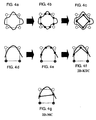
- FIGS. 4a to 4c are exemplary views showing a difference of cutting points in rectangular cells between MC and Kitta cubes (KTC).
- KTC Kitta cubes
- FIG. 4a shows an extreme example. Essentially similar defects frequently occur, and FIG. 4d shows an defect example. Such defects frequently occur at an intersection of a curved boundary surface and a cell edge.
- FIG. 4f In the case of the KTC, this situation is approximated as shown in FIG. 4f.
- FIGS. 4c and 4f show two-dimensional examples. In three-dimensional representation, more cases can be represented only by the KTC. It can be understood that the KTC has much richer power of representation than the MC at equal resolution.
- FIGS. 5a and 5b are views showing a difference of cutting points on edges between the conventional MC and the KTC of the present invention.
- the number of cutting points is limited to 0 or 1 on one edge.
- FIG. 5a in the case of the MC, one cutting point is generated on an edge only when signs of both ends of each edge of a cell oppose each other (positive and negative values).
- FIG. 5b when a cutting point is given on one edge, signs of both edges may not only oppose each other (positive and negative values) but also match each other.
- a cutting point can be represented only in a part of such cases.
- the cell in the case of the MC, the cell must be subdivided to represent a shape indicated by a closed solid line.
- subdivision of the cell becomes necessary to hold boundary data, and a storage capacity to store substantial data that integrates the shape and physical properties is accordingly increased exponentially. Furthermore, prevention of an increase in the storage capacity causes a difficulty of precisely representing a shape of a boundary part.
- objects of the invention are to provide a method and a program for converting boundary data into cell inner shape data, which can include all cell edge cutting points obtained by marching cubes (MC), and all cell edge cutting points unobtainable by the MC without omission, and thereby include cell inner shape data constituted of boundaries that connect the cell edge cutting points without omission.
- MC marching cubes
- a method and a program for converting boundary data into cell inner shape data characterized by comprising: a division step (A) of dividing external data (12) constituted of boundary data of an object into cells (13) in an orthogonal grid; a cutting point deciding step (B) of deciding an intersection point of the boundary data and a cell edge as a cell edge cutting point; a boundary deciding step (C) of deciding a boundary connecting formed by the cell edge cutting points as the cell inner shape data; a cell classification step (D) of classifying the divided cells into a nonboundary cell (13a) including no boundary surface and a boundary cell (13b) including a boundary surface; and a boundary cell data classification step (E) of classifying cell data constituting the boundary cell into internal cell data inside the cell inner shape data and external cell data outside the cell inner shape data.
- the division step (A) and the cell classification step (D) it is possible to store the external data (12) of the object as a cell hierarchy in which the external cell (12) is divided into the cells (13) in an orthogonal grid by a small storage capacity.
- the intersection point of the boundary data and the cell edge is decided as the cell edge cutting point.
- the intersection point of the boundary data and the cell edge is decided as the cell edge cutting point.
- the boundary formed by connecting the obtained cell edge cutting points is decided as the cell inner shape data.
- the boundary formed by connecting the obtained cell edge cutting points is decided as the cell inner shape data.
- the cell data constituting the boundary cell are classified into the internal cell data inside the cell inner shape data and the external cell data outside the cell inner shape data.
- the cell data is classified into the internal cell data inside the cell inner shape data and the external cell data outside the cell inner shape data.
- cell inner shape data patterns that become equivalence classes by three-dimensional rotational operation are decided as identical patterns so that the cell inner shape data patterns are classified into 22 patterns.
- the cell edge cutting point patterns that become equivalence classes by an inversion operation regarding presence/nonpresence of cutting points are decided as identical patterns so that the cell edge cutting point patterns are classified into 87 patterns in which the number of the cell edge cutting points is 0 to 6.
- a boundary surface formed by connecting the cell edge cutting points is decided as the cell inner shape data for all the patterns.
- FIG. 6 is a flowchart of a method and a program for converting data according to the present invention. As shown, each of the method and the program of the invention comprises a division step (A), a cutting point deciding step (B), a boundary deciding step (C), a cell classification step (D), and a boundary cell data classification step (E).
- A division step
- B cutting point deciding step
- C boundary deciding step
- D cell classification step
- E boundary cell data classification step
- External data 12 input from the outside is polygon data indicating a polyhedron, a tetrahedron or hexahedron element used for a finite element method, curved surface data used for three-dimensional CAD or a CG tool, or data in which the other solid surface is represented by information containing a partial plane or curved surface.
- the external data 12 may be (1) data directly prepared by a human input through a boundary surface of V-CAD's own (V-boundary surface), (2) surface digitized data of a measuring device, a sensor, a digitizer or the like, and (3) volume data containing internal information such as voxel data for CT scanning, MRI, and generally used for volume rendering.
- the external data 12 constituted of boundary data of an object obtained in an external data acquisition step (not shown) is divided into cells 13 of an orthogonal grid.
- the data is divided into rectangular cells by quad-tree division.
- the data is divided into rectangular parallelepiped cells 13 by oct-tree division.
- oct-tree representation i.e., oct-tree space division
- a reference rectangular parallelepiped 13 including a target solid (object) is divided into 8 parts, and 8-division processing is recursively repeated to a specified cell size until no more boundary surfaces are included in each region.
- one space region obtained by oct-tree space division is called a cell 13.
- the cell is rectangular or rectangular parallelepiped.
- the rectangle or rectangular parallelepiped is a square or a cube in a special case, but more generally it may be a quadrangle or a hexahedron in which edges do not cross each other at a right angle.
- a region occupying a space is represented by a hierarchical structure, the number of divisions or resolution of the cell. Accordingly, the object is represented by stacking cells different from one another in size in the entire space.
- the intersection point patterns since there are many patterns, it is further possible to reproduce 144 patterns of 7 to 12 cutting points from 87 patterns of 0 to 6 cell edge cutting points by deciding as identical patterns the intersection point patterns that become equivalence classes by an inversion operation regarding presence/nonpresence of cutting points.
- a boundary formed by connecting the obtained cell edge cutting points is decided as the cell inner shape data.
- cutting segment arrangement made by connecting the cell edge cutting points is decided as the cell inner shape data for all the 6 patterns of the cell edge cutting points. More specifically, it is advised to classify the cell inner shape data into 22 kinds of cell inner shape patterns (described later) by deciding as identical patterns the cell inner shape data that become equivalence classes by a three-dimensional rotational operation.
- acquisition of the approximate boundary surface made by connecting the cell edge cutting points may be referred to as "plane formation”.
- the cells obtained by the division are classified into a nonboundary cell 13a including no boundary surface and a boundary cell 13b including a boundary surface.
- quad-tree or oct-tree division is used to represent the boundary cell 13b, a cell completely included inside is decided as an internal cell 13a having a largest size, and a cell including boundary information from the external data 12 is decided as a boundary cell 13b.
- cell data constituting a boundary cell are classified into internal cell data and external cell data.
- the internal cell data is inside the cell inner shape data
- the external cell data is outside the cell inner shape data.
- the steps (A) to (E) are repeated when necessary. Additionally, for example, simulations of designing, analyzing, fabricating, assembling, testing and the like are sequentially carried out by using the obtained V-CAD data, and the result is output as CAM or polygon data, for example at an output step.
- the conversion program of the invention is a computer program for executing the aforementioned steps (A) to (E), and incorporated in a computer to be used.
- the invention provides a novel method for generating a cell inner surface. This completely includes cell inner surface patterns of a marching cube method, and is a more general method.
- cell inner surface generation patterns from the cutting points are completely defined in two-dimensional representation. That is, enumeration (6 patterns) of equivalence classes of cutting point arrangement is performed, and all possibilities (22 patterns) of cell inner surface formation are collected for all arrangement of cutting points.
- equivalence classes are enumerated (144 patterns) for the cutting point arrangement according to the invention.
- cutting points can be connected on 6 surfaces of a cube by line segments without intersection for more than half of all the arranged cutting points. If such a closed loop is constructed, it is possible to relatively easily form a cell inner surface in which the loop is an outer edge.
- arrangement of cutting points which has one closed loop passing through all the cutting points once corresponds to 87 patterns among the 144 patterns.
- An example of a cell inner surface formed by using a closed loop will be described later.
- a surface shape of conventional type CAD is read into a cell space, an intersection point (cutting point) of a surface and a cell edge is recorded, and the original surface shape is accordingly approximated to a triangular surface.
- the MC has come into wide use since the surface is strongly formed by a simple algorithm.
- Contents of the MC can be summarized as the following two: (1) pattern classification of cutting point arrangement, and (2) definition of formation of a cell inner surface for each cutting point arrangement (i.e., how to connect cutting points).
- a problem of ambiguity of the MC is that formation of a cell inner surface of (2) is not always unique. However, it is not difficult to specify unique formation of a surface. For example, if ambiguity arises, it is advised to decide formation of a cell inner surface to interconnect vertexes of large values, or vertexes of small values.
- the strong MC means that the cell inner surface can be formed without holes by such decision, i.e., a triangular edge constituting the cell inner surface is shared by 2 triangles.
- the invention provides novel broad-sense means for approximating a surface shape by a cut triangle in which a cutting point is a vertex, which is referred to as Kitta cubes (abbreviated to KTC hereinafter) (Kitta is a Japanese word meaning "cut").
- the cell inner surface is strongly formed. However, it does not necessarily mean that the shape is correctly represented.
- FIGS. 4a to 4c Before describing accurate definition of the KTC, a two-dimensional typical example showing that the KTC can represent the shape more accurately than the MC is given (each of FIGS. 4a to 4c).
- the aforementioned MC in a situation as shown in FIG. 4a, 4 vertexes of a square cell have the same sign as they are located outside the shape, and thus no cutting points are disposed on 4 edges of the cell. As a result, no cell inner surface is formed at all in the case of FIG. 4a. From the standpoint of the MC, this means that current resolution is too rough to represent the shape.
- FIG. 4b shows an extreme example. However, essentially similar defects frequently occur, and FIG. 4d shows such an example. The defects frequently occur at an intersection of a curved boundary surface and a cell edge. In the case of the KTC, this situation is approximated to that of FIG. 4f. In the case of the MC, it is approximated to that of FIG. 4g.
- FIGS. 4c and 4f show two-dimensional examples. In three-dimensional representation, more cases can be represented only by the KTC. It can be understood that the KTC is much higher in power of representation than the MC at equal resolution.
- the KTC completely includes the MC (described later). That is, MC patterns constitute a partial aggregation of KTC patterns. In this sense, it is only natural that the KTC is higher in power of representation than the MC.
- the number of cutting points on one edge is limited to one.
- the number of cutting points is limited to 0 or 1.
- the KTC is constructed within a framework in which the number of cutting points is 0 or 1 on one edge. A difference between the two is that one cutting point is disposed on one edge only when signs of both ends of each edge of the cell oppose each other (positive and negative) (FIG.
- the case of the MC is referred to as “narrow-sense condition that the number of cutting points on one edge is at most one”
- the case of the KTC is referred to as “broad-sense condition that the number of cutting points on one edge is at most one” to clearly distinguish them from each other.
- the broad-sense condition that the number of cutting points on one edge is at most one completely include the narrow-sense condition that the number of cutting points on one edge is at most one.
- Two-dimensional Kitta cubes KTC (2D-KTC) is constructed in two-dimensional representation.
- the 2D-KTC is constructed at 2 stages.
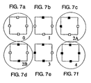
- the first stage is classification of cutting point arrangement for 4 edges of a square.
- the 6 patterns are integrated into 4 patterns. However, in cutting segment arrangement of the section 2. 2, all the 6 patterns must be defined.
- Degrees of reduction for the arrangements in FIGS. 7a to 7f are 1, 4, 4, 2, 4, 1 in order (16 if added together).
- the "degree of reduction” means the number of arrangements integrated into one equivalence class by a rotational operation.
- the process proceeds to the second stage of the 2D-KTC.
- all the possibilities of cutting segment arrangements are collected for each of the 6 kinds of cutting point arrangements obtained in the section 2. 1.
- One edge is shared by two cells. If there is one cutting point on the edge, even when the edge is not used in one cell to form a cell inner line, there is a possibility that it will be used in the other cell.
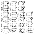
- FIGS. 8a to 8v show all arrangements of cutting segments in the 2D-KTC, which are results of investigating all possibilities of line setting for each of the 6 kinds of cutting point arrangement obtained in the section 2. 1.
- circled squares are present in the 2D-MC. These apparently constitute only a partial aggregation of the 2D-KTC.
- a three-dimensional rotational operation is used when equivalence classes are counted. Assuming that connection of cutting segments have no diversity, i.e., intersections or branches, it is possible to differently color 4 vertexes of FIGS. 8a to 8v black and white. Different from the case of the MC, the different coloring is executed after arrangement of the cutting segments. Paying attention to cutting segment arrangement patters of FIGS. 8a to 8v, similar types emerge as in the case of, e.g., 2A(1), 3(5), 4(9). However, they cannot be omitted for the purpose of including ways of surface formation for all the cutting point arrangements. Incidentally, there are 10 cases if 22 kinds of patterns drawn in FIGS. 8a to 8v are classified by cutting segment arrangement.
- equations (1) and (2) of an [expression 1] are established, it can be understood that an inversion operation regarding presence of cutting points in arrangement in which the number of cutting points is 0 to 5 is carried out to obtain arrangement in which the number of cutting points is 7 to 12, and correspondence is set for equivalence classes by the inversion operation.
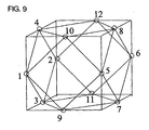
- Indexes of 1 to 12 are first given for sides of a cube as shown in FIG. 9.
- 48 substitution operations are enabled by adding a mirroring operation to 24 rotational operations of a group of regular octahedra.
- Checking is made on whether the indexes of the 4096 arrangements are new or old one by one in order from the first. In this case, past appearance of the same arrangements can be determined by executing 48 operations for individual arrangements and collating them with the existing list.
- Table 2 144 kinds of cutting point arrangements different from one another can be obtained at the end.
- the equivalence classes in which the number of cutting points is 7 to 12 can be reproduced from the equivalence classes in which the number of cutting points is 0 to 5.
- totally 87 patterns in which the number of cutting points is 0 to 6 are collected in Table 3, and shown in FIGS. 10a to 10ad, FIGS. 11a to 11aa, and FIGS. 12a to 12ad. Circled cubes are present in the 3D-MC.
- cutting point arrangement cases of the MC constitute only a part of KTC cutting point arrangement cases.
- FIGS. 10a to 10ad, FIGS. 11a to 11aa, and FIGS. 12a to 12ad a case in which the number of cutting points is 7 to 12 is omitted.
- 144 patterns are necessary when arrangement of cut triangles is considered.
- the 144 kinds of arrangements can all emerge as cutting point arrangements when a surface shape is actually read into a cell space.
- Table 7 of the appendix B shows correspondence of all the cutting point arrangements between the 3D-MC and the 3D-KTC. It can be understood that the MC arrangements constitute only a part of the KTC arrangements.
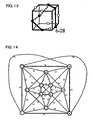
- FIG. 13 shows an example in which segments made by connecting all given cutting points constitutes a closed loop on a surface of a cell. It is a cubic octahedron (one of semiregular polyhedra. 14-hedron constituted of 8 regular triangles and 6 squares) that is shown together with the cell in FIG. 9. Even if a position of a cutting point is a center point of each edge, generality is not lost when cutting point arrangements are counted, or a closed loop is considered.
- This cubic octahedron is a convex hull for 12 center points on 12 edges.
- paths for tracing the closed loop there are totally 36 paths constituted of two diagonal lines of each square surface of the 14-hedron, i.e., 12 diagonal lines, and 24 edges which the 14-hedron originally has.
- FIG. 14 shows a relation between 12 vertexes of the semiregular polyhedron and paths of 36 edges as a graph on a plane. Enumeration of Hamilton closed paths will be described with reference to this drawing. In this graph, the 12 vertexes are all equal at values of 6, and enumeration here needs to be carried out only from one vertex. Paths permitted as Hamilton closed paths are those which pass through all cutting points given on the surface of the cube so as to return to the start point without passing through the same path or cutting point again in the midway. A result of the enumeration is 87 kinds which constitute more than half of the total 144 kinds of the cutting point arrangements, the number of cutting points being 0 to 12 therein, and have non-self-intersection Hamilton paths.
- V-CAD has physical information as cell internal information as described above, and multimedia can be dealt with.
- a plurality of substances occupy the inside of the cell on a boundary surface of a different material.
- the number of substances in one cell is preferably limited to two by executing given processing.
- Many of cell inner surfaces formed by the closed loops are advantageous in that the cell is divided into two.
- all the closed loops do not necessarily divide the cell into two.
- the cell may not be divided even if a closed loop is formed as shown in FIG. 15.
- FIGS. 16a to 16c show that the cell can be divided into two or three depending on a way of triangular division in which the closed loop is set as an edge even if the closed loop is formed.
- the cell may be divided into two even if one closed loop passing through all the cutting points is not formed.
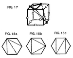
- FIG. 17 shows such an example.
- the closed loop is constructed, it is easy in many cases to form a cell inner surface in which the closed loop is set as an edge.
- a problem of triangularly dividing the cell inner surface has a relation to a problem of triangular division of a polygon on a plane. It is known that the number of triangular division patterns is represented by using Catalan numbers. The Catalan numbers and the triangular division are described later in the appendix C.
- FIGS. 19a and 19b show restoration thereof based on cutting point information. These are generated from closed loops which are only parts of KTC surface formation possibility, but they have sufficient power of representation.
- the cutting point arrangements corresponding to the closed loops are only parts of the KTC, but they do not fall within the cutting point arrangement framework of the MC. While there are only totally 14 cutting point arrangements in the MC, it is 87 kinds among the 144 cutting point arrangements of the KTC that correspond to the closed loops as described above. As an example, the cutting point arrangements of FIGS. 16a to 16c can constitute closed loops, but they are patterns nonpresent in the MC. Further, a three-dimensional version of FIG. 4f is shown in FIG. 16d.
- the KTC is capable of more precise shape representation than the MC when they are compared at equal resolution. This is only natural because the equivalence classes of the cutting point triangular arrangement of the KTC completely include those of the MC.
- the present invention precisely presents the diversity exhibited by the KTC on the assumption of only the broad-sense condition that the number of cutting points on one edge is at most one.
- Appendix A Two-dimensional Marching Cubes (2D-MC)
- FIGS. 2a to 2d show 4 kinds of equivalence classes of the 2D-MC. These 4 patterns are obtained by using only a black and white inversion operation and a three-dimensional rotational operation on 4 vertexes of a cell. Since the MC abides by the narrow-sense condition that the number of cutting points on one edge is at most, 4 vertex patterns differently colored black and white and cutting point arrangement cases correspond to each other by 1 to 1.
- indexes of mc-0, mc-1, mc-2, and mc-3 are allocated to patterns.
- Table 4 shows correspondence between the number of equivalence classes regarding cutting point arrangement, and the total number of arrangements.
- Table 5 shows correspondence between the cutting point arrangement of the MC and the cutting point arrangement of the KTC.
- 2D-MC index in FIGS. 2a to 2d 0 1 2 3
- 2D-KTC index in FIGS. 8a to 8v 0(1) 2A(1) 2B(1) 4(4)
- Appendix B Three-dimensional Marching Cubes (3D-MC)
- FIGS. 3a to 3n show all the equivalence classes of the MC cutting point arrangement.
- Operations used for classification are a black and white inversion operation, a rotational operation and a mirroring operation on vertexes.
- Table 6 shows an aggregation of these regarding the number of cutting points.
- the MC is represented by totally 15 drawings of 0 to 14 in accordance with a normal MC original thesis, but only 14 are shown here (FIGS. 3a to 3n).
- the omitted MC-14 is reflectional symmetry of the MC-11. Since the MC-15 is uniquely decided by a mirroring operation after surface formation of the MC-11 is decided, it is omitted to maintain consistency of description of the invention (use of mirroring operation for enumeration of equivalence classes).
- FIGS. 3a to 3b are similar in lining-up to drawings of the original thesis, but a cell inner surface is omitted, and the MC-14 is omitted for the aforementioned reason.
- Table 7 shows correspondence of all the cases between the MC and the KTC. 3D-MC index in FIGS. 3a to 3N 0 1 2 3 4 5 6 7 8 9 10 11 12 13 3D-KTC index in FIGS. 10a to 10ad, FIGS. 11a to 11aa, FIGS. 12a to 12ad 0-1 3-6 4-12 6-6 6-29 5-18 7-18 9-6 4-7 6-30 8-7 6-28 8-12 12-1
- Appendix C Triangular division and Catalan number of polygon
- a problem of a folded surface in which a closed loop tracing a cell surface is an edge, i.e., triangular division of the inside of the loop, can come down to a problem of triangularly dividing a convex polygon shape on a plane in many cases. (If the entire closed loop is not planar, i.e., if a greatly bent cell inner surface is formed by the closed loop, the problem may not come down to the latter problem).
- Catalan number C m is represented by an equation (3) of an expression (2).
- the convex n square shape convex polygon shape
- An obtained number T n is represented by an equation (4) of the expression (2).
- FIGS. 18a to 18c show representative equivalence classes of 6, 2 and 6 triangular division methods. It can be confirmed that these are added to be 14.
- the division step (A) and the cell classification step (D) it is possible to store the external data (12) of the object as a cell hierarchy in which the external cell (12) is divided into the orthogonal cells (13) by a small storage capacity.
- the intersection point of the boundary data and the cell edge is decided as the cell edge cutting point.
- the intersection point of the boundary data and the cell edge is decided as the cell edge cutting point.
- the boundary formed by connecting the obtained cell edge cutting points is decided as the cell inner shape data.
- the boundary formed by connecting the obtained cell edge cutting points is decided as the cell inner shape data.
- the cell data constituting the boundary cell are classified into the internal cell data inside the cell inner shape data and the external cell data outside the cell inner shape data.
- the cell data is classified into the internal cell data inside the cell inner shape data and the external cell data outside the cell inner shape data.
- the method and the program of the invention for converting the boundary data into the cell inner shape data are advantageous in that it is possible to include all the cell edge cutting points by the MC and all the other cell edge cutting points without omission under the condition that the number of cutting points on one edge is at most one, and it is thereby possible to include the cell inner shape data constituted of the boundary connecting the cell edge cutting points without omission.
Landscapes
- Engineering & Computer Science (AREA)
- Physics & Mathematics (AREA)
- Theoretical Computer Science (AREA)
- Geometry (AREA)
- General Physics & Mathematics (AREA)
- Computer Graphics (AREA)
- Software Systems (AREA)
- Computer Hardware Design (AREA)
- Evolutionary Computation (AREA)
- General Engineering & Computer Science (AREA)
- Processing Or Creating Images (AREA)
- Image Generation (AREA)
Applications Claiming Priority (3)
| Application Number | Priority Date | Filing Date | Title |
|---|---|---|---|
| JP2002053575 | 2002-02-28 | ||
| JP2002053575 | 2002-02-28 | ||
| PCT/JP2003/002197 WO2003073335A1 (en) | 2002-02-28 | 2003-02-27 | Method and program for converting boundary data into in-cell shape |
Publications (2)
| Publication Number | Publication Date |
|---|---|
| EP1484698A1 true EP1484698A1 (de) | 2004-12-08 |
| EP1484698A4 EP1484698A4 (de) | 2013-06-12 |
Family
ID=27764365
Family Applications (1)
| Application Number | Title | Priority Date | Filing Date |
|---|---|---|---|
| EP03707132.1A Withdrawn EP1484698A4 (de) | 2002-02-28 | 2003-02-27 | Verfahren und programm zum umsetzen von grenzdaten in eine in-zellen-form |
Country Status (5)
| Country | Link |
|---|---|
| US (1) | US7321366B2 (de) |
| EP (1) | EP1484698A4 (de) |
| JP (1) | JP4320425B2 (de) |
| CN (1) | CN100423009C (de) |
| WO (1) | WO2003073335A1 (de) |
Cited By (1)
| Publication number | Priority date | Publication date | Assignee | Title |
|---|---|---|---|---|
| WO2008129538A1 (en) * | 2007-04-18 | 2008-10-30 | Camero-Tech Ltd. | Method and system for volume rendering |
Families Citing this family (9)
| Publication number | Priority date | Publication date | Assignee | Title |
|---|---|---|---|---|
| JP4381743B2 (ja) | 2003-07-16 | 2009-12-09 | 独立行政法人理化学研究所 | 境界表現データからボリュームデータを生成する方法及びそのプログラム |
| JP4526063B2 (ja) | 2004-05-06 | 2010-08-18 | 独立行政法人理化学研究所 | ボリュームデータのセルラベリング方法とそのプログラムとボリュームデータのセルラベリング装置 |
| JP4605772B2 (ja) | 2005-03-09 | 2011-01-05 | 独立行政法人理化学研究所 | 境界面情報の生成方法、その生成プログラム及びその生成システム |
| JP4783100B2 (ja) * | 2005-09-12 | 2011-09-28 | 独立行政法人理化学研究所 | 境界データのセル内形状データへの変換方法とその変換プログラム |
| US8462161B1 (en) * | 2009-01-20 | 2013-06-11 | Kount Inc. | System and method for fast component enumeration in graphs with implicit edges |
| KR101213494B1 (ko) * | 2010-05-12 | 2012-12-20 | 삼성디스플레이 주식회사 | 입체형 표시장치, 플렉서블 표시장치 및 상기 표시장치들의 제조방법 |
| FR3013126B1 (fr) * | 2013-11-14 | 2015-12-04 | IFP Energies Nouvelles | Procede de construction d'une grille representative de la distribution d'une propriete par simulation statistique multipoint conditionnelle |
| US10353352B2 (en) * | 2017-02-22 | 2019-07-16 | Mitsubishi Electric Research Laboratories, Inc. | System and method for distributed machining simulation |
| CN111406408B (zh) * | 2019-01-11 | 2023-02-21 | 深圳市大疆创新科技有限公司 | 三维数据点的编解码方法和装置 |
Family Cites Families (56)
| Publication number | Priority date | Publication date | Assignee | Title |
|---|---|---|---|---|
| DE2547477C3 (de) | 1975-10-23 | 1981-01-22 | Maschinenfabrik Rissen Gmbh, 2000 Hamburg | Verfahren und Vorrichtung zum Tiefziehen einer Folie aus thermoplastischem Werkstoff |
| US4694404A (en) * | 1984-01-12 | 1987-09-15 | Key Bank N.A. | High-speed image generation of complex solid objects using octree encoding |
| US4665492A (en) | 1984-07-02 | 1987-05-12 | Masters William E | Computer automated manufacturing process and system |
| US4729098A (en) * | 1985-06-05 | 1988-03-01 | General Electric Company | System and method employing nonlinear interpolation for the display of surface structures contained within the interior region of a solid body |
| US4710876A (en) * | 1985-06-05 | 1987-12-01 | General Electric Company | System and method for the display of surface structures contained within the interior region of a solid body |
| US4719585A (en) * | 1985-08-28 | 1988-01-12 | General Electric Company | Dividing cubes system and method for the display of surface structures contained within the interior region of a solid body |
| US5197013A (en) | 1987-07-28 | 1993-03-23 | David M. Dundorf | Method of forming a carved sign using an axially rotating carving tool |
| JPH0767576B2 (ja) | 1987-11-18 | 1995-07-26 | ファナック株式会社 | パンチ取り付け用部品の穴位置定義方法 |
| JP2920195B2 (ja) | 1989-03-10 | 1999-07-19 | 株式会社日立製作所 | 形状変換方法及び装置 |
| US5014207A (en) | 1989-04-21 | 1991-05-07 | E. I. Du Pont De Nemours And Company | Solid imaging system |
| JPH0741514B2 (ja) | 1990-07-17 | 1995-05-10 | 日立精機株式会社 | 対話型数値制御装置における工具選定方法 |
| JPH0540224A (ja) * | 1990-07-26 | 1993-02-19 | Fuji Photo Film Co Ltd | 走査型顕微鏡 |
| JP2597778B2 (ja) | 1991-01-03 | 1997-04-09 | ストラタシイス,インコーポレイテッド | 三次元対象物組み立てシステム及び組み立て方法 |
| US5166876A (en) * | 1991-01-16 | 1992-11-24 | General Electric Company | System and method for detecting internal structures contained within the interior region of a solid object |
| US5594652A (en) | 1991-01-31 | 1997-01-14 | Texas Instruments Incorporated | Method and apparatus for the computer-controlled manufacture of three-dimensional objects from computer data |
| US5345490A (en) | 1991-06-28 | 1994-09-06 | General Electric Company | Method and apparatus for converting computed tomography (CT) data into finite element models |
| US5510066A (en) | 1992-08-14 | 1996-04-23 | Guild Associates, Inc. | Method for free-formation of a free-standing, three-dimensional body |
| US5517602A (en) | 1992-12-03 | 1996-05-14 | Hewlett-Packard Company | Method and apparatus for generating a topologically consistent visual representation of a three dimensional surface |
| JPH06315849A (ja) | 1993-03-04 | 1994-11-15 | Nikon Corp | 研磨加工用プログラムの作成方法及び それを用いた作成装置 |
| JPH06348862A (ja) * | 1993-06-11 | 1994-12-22 | Toshiba Corp | 三次元等値面生成方法 |
| JP3340198B2 (ja) | 1993-08-12 | 2002-11-05 | 株式会社東芝 | 形状復元装置 |
| JPH07334541A (ja) | 1994-06-08 | 1995-12-22 | Hitachi Ltd | 数値解析用要素作成システム |
| US5594651A (en) | 1995-02-14 | 1997-01-14 | St. Ville; James A. | Method and apparatus for manufacturing objects having optimized response characteristics |
| US6136252A (en) | 1995-09-27 | 2000-10-24 | 3D Systems, Inc. | Apparatus for electro-chemical deposition with thermal anneal chamber |
| JP3150066B2 (ja) | 1996-07-16 | 2001-03-26 | 有限会社アロアロ・インターナショナル | 造形装置および方法 |
| US6075538A (en) | 1996-07-25 | 2000-06-13 | Institute Of High Performance Computing | Time and space efficient data structure and method and apparatus for using the same for surface rendering |
| JPH1063873A (ja) | 1996-08-23 | 1998-03-06 | Atr Tsushin Syst Kenkyusho:Kk | 八分木生成方法 |
| WO1999034336A1 (en) | 1997-12-29 | 1999-07-08 | The United States Of America, Represented By The Administrator Of The National Aeronautics And Space Administration (Nasa) | Triangle geometry processing for surface modeling and cartesian grid generation |
| JP3344558B2 (ja) | 1998-02-26 | 2002-11-11 | 理化学研究所 | 通電ドレッシング研削方法及び装置 |
| JP2000182081A (ja) | 1998-12-14 | 2000-06-30 | Suzuki Motor Corp | 解析モデル作成方法および装置並びに解析モデル作成用プログラム若しくは解析モデルデータを記憶した記憶媒体 |
| JP2000194881A (ja) | 1998-12-24 | 2000-07-14 | Suzuki Motor Corp | 解析モデルを作成する方法および装置並びに解析モデルデータ作成用プログラム若しくは解析モデルデータを記憶した記憶媒体 |
| US6405095B1 (en) | 1999-05-25 | 2002-06-11 | Nanotek Instruments, Inc. | Rapid prototyping and tooling system |
| JP3388203B2 (ja) | 1999-05-28 | 2003-03-17 | 株式会社半導体先端テクノロジーズ | 形状シミュレーション方法、装置および記録媒体 |
| JP2001025023A (ja) | 1999-07-09 | 2001-01-26 | Nippon Telegr & Teleph Corp <Ntt> | 映像ストリーム配信方法、配信システムならびに該方法のプログラムを記録した記録媒体 |
| JP2001022961A (ja) | 1999-07-13 | 2001-01-26 | Ricoh Co Ltd | 非一様ボリュームモデルからの同位相面生成方法 |
| US6214279B1 (en) | 1999-10-02 | 2001-04-10 | Nanotek Instruments, Inc. | Apparatus and process for freeform fabrication of composite reinforcement preforms |
| US6627835B1 (en) | 2000-02-02 | 2003-09-30 | Purdue Research Foundation | Three dimensional object fabrication techniques |
| US6639597B1 (en) | 2000-02-28 | 2003-10-28 | Mitsubishi Electric Research Laboratories Inc | Visibility splatting and image reconstruction for surface elements |
| WO2001075538A1 (en) | 2000-03-31 | 2001-10-11 | Incs Inc. | Data generating device, data generating method and data generating program |
| US6968075B1 (en) | 2000-05-09 | 2005-11-22 | Chang Kurt C | System and method for three-dimensional shape and size measurement |
| US6606528B1 (en) | 2000-06-21 | 2003-08-12 | The Boeing Company | Method for creating computer-aided design (CAD) solid models from numerically controlled (NC) machine instructions |
| JP2002024306A (ja) | 2000-07-05 | 2002-01-25 | Suzuki Motor Corp | 解析モデルデータ作成方法及び装置並びに解析モデルデータ作成用プログラムを記録した記録媒体。 |
| DE60109541T2 (de) | 2000-09-18 | 2006-02-16 | Fuji Photo Film Co., Ltd., Minami-Ashigara | System zum Auswählen, Anzeigen und Speichern von Kunstknochenschablonen und Aufzeichnungsträger dafür |
| WO2002023406A1 (en) | 2000-09-18 | 2002-03-21 | Doodlebug Online, Inc. | System and method for accessing data on content servers via a central authorization host |
| WO2002035250A1 (en) | 2000-10-20 | 2002-05-02 | Duke University | Single-shot epi with signal recovery from susceptibility-induced losses |
| US6471800B2 (en) | 2000-11-29 | 2002-10-29 | Nanotek Instruments, Inc. | Layer-additive method and apparatus for freeform fabrication of 3-D objects |
| US20020113331A1 (en) | 2000-12-20 | 2002-08-22 | Tan Zhang | Freeform fabrication method using extrusion of non-cross-linking reactive prepolymers |
| GB0117157D0 (en) * | 2001-07-16 | 2001-09-05 | Imec Inter Uni Micro Electr | Extraction, hierarchical representation and flexible compression of surface meshes derived from 3D data |
| JP3468464B2 (ja) | 2001-02-01 | 2003-11-17 | 理化学研究所 | 形状と物性を統合したボリュームデータ生成方法 |
| JP2004521423A (ja) | 2001-03-12 | 2004-07-15 | コーニンクレッカ フィリップス エレクトロニクス エヌ ヴィ | 8分木を用いた多数の画像からの3次元表現の生成 |
| JP4703907B2 (ja) | 2001-07-31 | 2011-06-15 | 富士重工業株式会社 | 物体の表面格子生成方法 |
| WO2003016031A1 (en) | 2001-08-16 | 2003-02-27 | Riken | Rapid prototyping method and device using v-cad data |
| US7110852B2 (en) | 2001-08-16 | 2006-09-19 | Riken | Die machining method and device by V-CAD data |
| US6504742B1 (en) | 2001-10-31 | 2003-01-07 | Hewlett-Packard Company | 3-D memory device for large storage capacity |
| TW515010B (en) * | 2001-12-11 | 2002-12-21 | United Microelectronics Corp | Method for electroplated metal annealing process |
| SE524439C2 (sv) | 2002-12-19 | 2004-08-10 | Arcam Ab | Anordning samt metod för framställande av en tredimensionell produkt |
-
2003
- 2003-02-27 JP JP2003571956A patent/JP4320425B2/ja not_active Expired - Fee Related
- 2003-02-27 EP EP03707132.1A patent/EP1484698A4/de not_active Withdrawn
- 2003-02-27 WO PCT/JP2003/002197 patent/WO2003073335A1/ja not_active Ceased
- 2003-02-27 CN CNB038048620A patent/CN100423009C/zh not_active Expired - Fee Related
- 2003-02-27 US US10/505,224 patent/US7321366B2/en not_active Expired - Fee Related
Non-Patent Citations (6)
| Title |
|---|
| KELA A: "HIERARCHICAL OCTREE APPROXIMATIONS FOR BOUNDARY PEPRESENTATION-BASED GEOMETRIC MODELS", COMPUTER AIDED DESIGN, ELSEVIER PUBLISHERS BV., BARKING, GB, vol. 21, no. 6, 1 July 1989 (1989-07-01), pages 355-362, XP000095156, ISSN: 0010-4485, DOI: 10.1016/0010-4485(89)90002-X * |
| KOBBELT L P ET AL: "FEATURE SENSITIVE SURFACE EXTRACTION FROM VOLUME DATA", COMPUTER GRAPHICS. SIGGRAPH 2001. CONFERENCE PROCEEDINGS. LOS ANGELES, CA, AUG. 12 - 17, 2001; [COMPUTER GRAPHICS PROCEEDINGS. SIGGRAPH], NEW YORK, NY : ACM, US, 12 August 2001 (2001-08-12), pages 57-66, XP001049874, ISBN: 978-1-58113-374-5 * |
| MONTANI C ET AL: "Discretized Marching Cubes", VISUALIZATION, 1994., VISUALIZATION '94, PROCEEDINGS., IEEE CONFERENCE ON WASHINGTON, DC, USA 17-21 OCT. 1994, LOS ALAMITOS, CA, USA,IEEE COMPUT. SOC, 17 October 1994 (1994-10-17), pages 281-287,CP32, XP010100593, DOI: 10.1109/VISUAL.1994.346308 ISBN: 978-0-8186-6627-8 * |
| ROCCHINI C ET AL: "Marching intersections: an efficient resampling algorithm for surface management", SHAPE MODELING AND APPLICATIONS, SMI 2001 INTERNATIONAL CONFERENCE ON. MAY 7-11, 2001, PISCATAWAY, NJ, USA,IEEE, 7 May 2001 (2001-05-07), pages 296-305, XP010541344, ISBN: 978-0-7695-0853-5 * |
| See also references of WO03073335A1 * |
| TAO JU ET AL: "Dual contouring of Hermite data", ACM TRANSACTIONS ON GRAPHICS (TOG), ACM, US, vol. 21, no. 3, 1 July 2002 (2002-07-01), pages 339-346, XP002404248, ISSN: 0730-0301 * |
Cited By (1)
| Publication number | Priority date | Publication date | Assignee | Title |
|---|---|---|---|---|
| WO2008129538A1 (en) * | 2007-04-18 | 2008-10-30 | Camero-Tech Ltd. | Method and system for volume rendering |
Also Published As
| Publication number | Publication date |
|---|---|
| JPWO2003073335A1 (ja) | 2005-06-23 |
| US20050216238A1 (en) | 2005-09-29 |
| WO2003073335A1 (en) | 2003-09-04 |
| EP1484698A4 (de) | 2013-06-12 |
| CN1639715A (zh) | 2005-07-13 |
| US7321366B2 (en) | 2008-01-22 |
| JP4320425B2 (ja) | 2009-08-26 |
| CN100423009C (zh) | 2008-10-01 |
Similar Documents
| Publication | Publication Date | Title |
|---|---|---|
| Thakur et al. | A survey of CAD model simplification techniques for physics-based simulation applications | |
| US7088363B2 (en) | Storage method of substantial data integrating shape and physical properties | |
| US8175734B2 (en) | Methods and system for enabling printing three-dimensional object models | |
| EP1645979A1 (de) | Verfahren und programm zur erzeugung von volumendaten aus grenzrepräsentationsdaten | |
| JP4349562B2 (ja) | 空間の識別方法とそのプログラム | |
| US7898540B2 (en) | Method and program for converting boundary data into cell inner shape data | |
| EP1484698A1 (de) | Verfahren und programm zum umsetzen von grenzdaten in eine in-zellen-form | |
| JP4255016B2 (ja) | 3次元形状データのセル内部データへの変換方法および変換プログラム | |
| JP4175536B2 (ja) | 境界データの内外判定方法とそのプログラム | |
| Kase et al. | Volume cad | |
| Burguet et al. | Strong thinning and polyhedric approximation of the surface of a voxel object | |
| JP4526063B2 (ja) | ボリュームデータのセルラベリング方法とそのプログラムとボリュームデータのセルラベリング装置 | |
| Untereiner et al. | n-Dimensional multiresolution representation of subdivision meshes with arbitrary topology | |
| CN120689545B (zh) | 一种三维模型的体素化处理方法及系统 | |
| CN119312543B (zh) | 基于brep的cad模型对比方法、设备和存储介质 | |
| Inui et al. | Contour-Type Cutter Path Computation Using Ultra-High-Resolution Dexel Model. | |
| Rassovsky | Cubical marching squares implementation | |
| Frischmann | Topological and geometric healing on solid models | |
| Bhaniramka | Isosurfacing in arbitrary dimensions | |
| Bajaja et al. | Quality Partitioned Meshing of Multi-Material Objects | |
| Sun | Surface reconstruction using gamma shapes | |
| Dietrich | SirTom-Structural information retaining Triangle-based Occlusion Management | |
| Renggli et al. | Quadtree techniques for the construction of structured auxiliary meshes | |
| Liu | Feature-based design of solids with local composition control |
Legal Events
| Date | Code | Title | Description |
|---|---|---|---|
| PUAI | Public reference made under article 153(3) epc to a published international application that has entered the european phase |
Free format text: ORIGINAL CODE: 0009012 |
|
| 17P | Request for examination filed |
Effective date: 20040819 |
|
| AK | Designated contracting states |
Kind code of ref document: A1 Designated state(s): DE FR GB |
|
| A4 | Supplementary search report drawn up and despatched |
Effective date: 20130515 |
|
| REG | Reference to a national code |
Ref country code: DE Ref legal event code: R108 |
|
| RIC1 | Information provided on ipc code assigned before grant |
Ipc: G06F 17/50 20060101AFI20130508BHEP Ipc: G06T 17/10 20060101ALI20130508BHEP Ipc: G06T 17/00 20060101ALI20130508BHEP |
|
| REG | Reference to a national code |
Ref country code: DE Ref legal event code: R108 Effective date: 20130612 |
|
| STAA | Information on the status of an ep patent application or granted ep patent |
Free format text: STATUS: THE APPLICATION IS DEEMED TO BE WITHDRAWN |
|
| 18D | Application deemed to be withdrawn |
Effective date: 20130814 |