EP1484721A2 - Münzpfandschloss für Einkaufs-, Gepäckwagen oder ähnliches - Google Patents
Münzpfandschloss für Einkaufs-, Gepäckwagen oder ähnliches Download PDFInfo
- Publication number
- EP1484721A2 EP1484721A2 EP04012698A EP04012698A EP1484721A2 EP 1484721 A2 EP1484721 A2 EP 1484721A2 EP 04012698 A EP04012698 A EP 04012698A EP 04012698 A EP04012698 A EP 04012698A EP 1484721 A2 EP1484721 A2 EP 1484721A2
- Authority
- EP
- European Patent Office
- Prior art keywords
- coin
- key
- operated lock
- token
- slit
- Prior art date
- Legal status (The legal status is an assumption and is not a legal conclusion. Google has not performed a legal analysis and makes no representation as to the accuracy of the status listed.)
- Granted
Links
- 238000000605 extraction Methods 0.000 claims abstract description 27
- 230000007246 mechanism Effects 0.000 claims abstract description 16
- 230000000694 effects Effects 0.000 claims description 12
- 230000037431 insertion Effects 0.000 claims description 10
- 238000003780 insertion Methods 0.000 claims description 10
- 238000006073 displacement reaction Methods 0.000 claims description 7
- 230000000295 complement effect Effects 0.000 claims description 6
- 239000000463 material Substances 0.000 claims description 5
- 230000015572 biosynthetic process Effects 0.000 claims description 4
- 239000002991 molded plastic Substances 0.000 claims description 3
- 230000008878 coupling Effects 0.000 claims 1
- 238000010168 coupling process Methods 0.000 claims 1
- 238000005859 coupling reaction Methods 0.000 claims 1
- 238000010276 construction Methods 0.000 description 3
- 238000005755 formation reaction Methods 0.000 description 3
- 230000005489 elastic deformation Effects 0.000 description 2
- 230000005484 gravity Effects 0.000 description 2
- 239000004033 plastic Substances 0.000 description 2
- 230000007717 exclusion Effects 0.000 description 1
- 230000003993 interaction Effects 0.000 description 1
- 238000004519 manufacturing process Methods 0.000 description 1
- 238000000465 moulding Methods 0.000 description 1
Images


Classifications
-
- G—PHYSICS
- G07—CHECKING-DEVICES
- G07F—COIN-FREED OR LIKE APPARATUS
- G07F7/00—Mechanisms actuated by objects other than coins to free or to actuate vending, hiring, coin or paper currency dispensing or refunding apparatus
- G07F7/06—Mechanisms actuated by objects other than coins to free or to actuate vending, hiring, coin or paper currency dispensing or refunding apparatus by returnable containers, i.e. reverse vending systems in which a user is rewarded for returning a container that serves as a token of value, e.g. bottles
- G07F7/0618—Mechanisms actuated by objects other than coins to free or to actuate vending, hiring, coin or paper currency dispensing or refunding apparatus by returnable containers, i.e. reverse vending systems in which a user is rewarded for returning a container that serves as a token of value, e.g. bottles by carts
- G07F7/0654—Mechanisms actuated by objects other than coins to free or to actuate vending, hiring, coin or paper currency dispensing or refunding apparatus by returnable containers, i.e. reverse vending systems in which a user is rewarded for returning a container that serves as a token of value, e.g. bottles by carts in which the lock functions according to a "pinching of the token" principle, i.e. the token is held between two members
Definitions
- the present invention relates to coin-operated locks for supermarket carts, luggage trolleys and the like, serving the function of securing, typically by means of chains, the carts arranged consecutively in rows, and to allow their withdrawal by users only as a result of the introduction of a coin or token into the coin-operated lock.
- the coin-operated lock can also secure the cart to a fixed body, instead of to an adjacent cart.
- Such coin-operated locks traditionally comprise a case having a slit for the introduction/extraction of the coin or token, and an opening for the introduction/extraction of the key. Inside the case is housed a mechanism comprising the following elements:.
- the coin-operated lock mechanism comprises a plurality of distinct elements assembled within the case, which are most metallic and include one or more springs.
- coin operated locks are applied on the front side of the cart, at a bar that constitutes a thrust handle: the bulk of known coin operated locks is ill suited with the need to use the thrust bar for the application, according to current tendencies, of accessories such as, in particular, displays of information for the user.
- the object of the present invention is to overcome the aforesaid drawbacks, and to provide a coin operated lock of the type described above whose mechanism has an extremely simplified arrangement, totally lacking metallic springs, and that is simple and economical to fabricate and has very limited bulk, thereby drastically reducing the dimensions of the case and hence of the coin operated lock as a whole.
- said object is achieved thanks to the fact that the aforesaid means for locking the key, the aforesaid actuator means, the aforesaid means for retaining the coin or token and the aforesaid disengagement means are formed in a single piece.
- the aforesaid means for extracting the key and/or the aforesaid means for expelling the coin or token are formed in a single piece with said means for locking the key, said actuator means, said means for retaining the coin or token and said disengagement means.
- the aforesaid single piece is constituted by a body made of moulded plastic material, oscillating about a single rotation pivot.
- Said pivot is preferably but not necessarily borne by the case.
- the actuator means conveniently coincide with the means for ejecting the coin or token and advantageously consist of an elastically springing arm of said single piece, which is integrally formed with an abutment with which co-operates a complementary stop formed in said case to retain the means for locking the key in the operative position; said abutment being disengageable from said complementary stop by the coin or token as a result of its introduction into the slit of the case, and being re-engageable with said complementary stop upon extraction of said coin or token relative to said slit.
- the means for locking the key can consist of at least one hook-shaped appendage of said single piece, engageable with an abutment part of the key as a result of its insertion into the opening of the case
- said abutment part of the key is formed by a generally cylindrical head
- the locking means include a pair of said hook appendages substantially configured in the manner of a fork for the engagement of said cylindrical head.
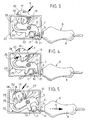
- a coin-operated lock for supermarket carts, luggage trolleys and the like comprises a case 1 formed by a small, flattened parallelepiped box including a base 2 and a lid 3.
- the box 1 has a slit 4 for the introduction/extraction of a coin or token designated by the reference M in Figures 3-8, and an opening 5 for the introduction/extraction of a key generically designated by the reference 6 in Figures 2-8.
- the opening 5 is formed by a circular hole, and said hole is positioned on one of the smaller lateral walls of the case 1, whilst the slit 4 is positioned on another one of the smaller lateral walls of said case 1.
- the case 1 of the coin-operated lock is applied to a cart, advantageously in the area of its thrust bar, in the position shown in Figure 1, i.e. with the slit 4 in the upper lateral wall.
- the wall of the case 1 bearing the hole 5 is the dorsal one, i.e. the one oriented towards the rear side of the cart.
- the case 1 contains a mechanism whereby when the key 6 is inserted in the hole 5, the introduction of the coin or token M through the slit 4 causes its extraction and, vice versa, when the coin or token M has been inserted in the case 1 through the slit 4, the introduction of the key 6 in the hole 5 causes its extraction.
- said mechanism is in practice constituted by a single piece, advantageously o moulded plastic material, globally designated by the reference 7.
- the embodiment of the piece 7 that shall be described below is the one corresponding to a particular and innovative conformation of the key 6 which, as shown in the drawings, consists of a grip body 8 from an end whereof projects a cylindrical element 9 followed by a cylindrical tang of lesser diameter 10 bearing an end head 11, also cylindrical, of greater diameter.
- the diameter of the cylindrical head 11 is slightly smaller than that of the hole 5, to allow its passage through said hole.
- the grip body 8 bears, at the opposite end, a chain 12 which is also advantageously made of plastic material, serving to anchor the key 6 to another cart.
- the key 6 is able to operate the coin-operated lock without the user's having to be concerned with introducing it through the hole 5 in a particular angular position, as is the case instead with traditional keys which, instead of the cylindrical head 11, are provided with a holed plate or the like.
- traditional keys which, instead of the cylindrical head 11, are provided with a holed plate or the like.
- the circular hole 5 shall be replaced by a slit or the like.
- the piece 7 which forms the coin-operated lock mechanism in a single piece comprises a central body 13 having a through hole 14, rotatably engageable on a pivot 15 projecting from the larger wall 16 of the base 2 of the case 1.
- the pivot 15 projects perpendicularly to the wall 16, integrally therewith, and is advantageously formed at its free end with a terminal 17 capable of contracting elastically in sectors which, when the piece 7 is mounted, is able axially to traverse its hole 14, engaging then in snap-on fashion beyond it.
- this characteristic is optional.
- the pivot 15 could be borne, instead of by the case 1, by the piece 7 (for example, integrally therewith) and could rotatably engage a corresponding support or hole in the case.
- the variant of the piece 7 shown in Figure 11 corresponds to the configuration thereof that is usable with a traditional key, or with holed engagement plate: in this case, the piece 7 differs from the one described previously solely because it has a single latching appendage 21 and a single thrust appendage 22, which in this case, too, are aligned to each other.
- Said formation essentially comprises three components: an inclined slide projection 27, situated below the rear end of the slit 4, an arresting seat 28 positioned below the front end of the slit 4, and an arched track 29 extending below the arresting recess 28.
- the arresting recess 28 and the track 29 co-operate with the terminal abutment 26 of the springing arm 23 of the piece 7.
- the piece 7 In the assembled condition of the coin-operated lock the piece 7 is mounted oscillating, as explained previously, on the pivot 15, whose axis is orthogonal to the directions of introduction/extraction F of the coin or token M and H of the key 6.
- the cradle-like seat 18 of the piece 7 is oriented towards the wall 16 of the base 2, i.e. towards the inclined guiding slide 27, and it is positioned below the slit 4, whilst the latching appendages 21 are oriented towards the hole 5.
- the initial position shown in Figure 3 is one in which the key 6 is engaged and locked in the coin-operated lock, by effect of the engagement of its cylindrical head 11 by the appendages 21 of the piece 7.
- the cylindrical head 11 is interposed between the latching appendages 21 and the thrust appendages 22, and the springing arm 23 is in a non-deformed position with its end abutment 26 engaged within the stopping recess 28.
- the piece 7 is locked in rotation relative to the case 1, thereby preventing by means of the latching appendages 21 the disengagement of the cylindrical head 11 and the extraction of the key 6 from the hole 5.
- the coin or token M must be introduced through the slit 4.
- the introduction of the coin M is conveniently performed from above, at first by simple gravity and then by means of a thrust operated manually downwards.
- the coin M is made to roll or slide along the inclined guiding slide 27 in the direction of insertion F.
- Said direction of insertion F is clearly directed obliquely, parallel to the slide 27, so that during its insertion the coin M moves towards the front end of the slit 4, intercepting with its lateral edge the end abutment 26 of the springing arm 23 in the manner shown in Figure 4.
- the coin M is entirely positioned below the front end of the slit 4, whilst simultaneously the latching appendages 21 free the cylindrical head 11 of the key 6 and the appendages 22 apply to said head 11 a thrust in the direction of the opening 5.
- the key 6 can be extracted from the case 1 through the opening 5, freeing the coin-operated lock and hence allowing the removal of the cart.
- the coin or token M remains positioned within the case 1 both by gravity, and by the presence of the securing arm 19 which does not allow it to exit from the slit 4.
- the other securing arm holds the coin M against the wall 16 of the base 12, preventing it from being subjected to skipping within the case 1 during the movements of the cart whereon the coin-operated lock is applied.
- the key 6 is thus blocked relative to the case 1, whilst the coin M can be withdrawn and extracted manually through the slit 4.
- This manoeuvre can be facilitated by applying an additional thrust on the key 6 towards the interior of the coin-operated lock, in such a way as to obtain a clockwise angular extra-travel of the piece 7 lifting the cradle-like seat 18 towards the slit 4 and, consequently, the coin M upwards.
- the arresting recess 28 it will naturally be necessary for the arresting recess 28 to be larger than the end abutment 26.
- the piece 7 may be adapted for use with traditional keys, and it may be formed with the pivot 15, also integrally.
- the positions of the slit 4 and of the opening 5 may be different from those illustrated, and such that the direction of insertion/extraction F and H respectively of the coin or token M and of the key 6 are different from those described with reference to the example. In any case, preferably said directions will not be mutually aligned as is normally the case in conventional coin-operated locks.
- the engagement between the abutment 26 of the springing arm 23 and the seat 28 of the case 1, in the inserted condition of the key 6 in the absence of the coin or token M, may be such that, if a force exceeding a threshold value is applied to extract the key, the piece 7 is freed in rotation in order to disengage the key and safeguard the lock-chain-cart system from breakage.
Landscapes
- Physics & Mathematics (AREA)
- General Physics & Mathematics (AREA)
- Coin-Freed Apparatuses For Hiring Articles (AREA)
- Handcart (AREA)
- Vehicle Step Arrangements And Article Storage (AREA)
- Compositions Of Macromolecular Compounds (AREA)
- Lock And Its Accessories (AREA)
Applications Claiming Priority (2)
| Application Number | Priority Date | Filing Date | Title |
|---|---|---|---|
| ITTO20030408 | 2003-06-03 | ||
| IT000408A ITTO20030408A1 (it) | 2003-06-03 | 2003-06-03 | Gettoniera per carrelli per supermercati, portabagagli e simili. |
Publications (3)
| Publication Number | Publication Date |
|---|---|
| EP1484721A2 true EP1484721A2 (de) | 2004-12-08 |
| EP1484721A3 EP1484721A3 (de) | 2005-04-13 |
| EP1484721B1 EP1484721B1 (de) | 2007-03-28 |
Family
ID=33156370
Family Applications (1)
| Application Number | Title | Priority Date | Filing Date |
|---|---|---|---|
| EP04012698A Expired - Lifetime EP1484721B1 (de) | 2003-06-03 | 2004-05-28 | Münzpfandschloss für Einkaufs-, Gepäckwagen oder ähnliches |
Country Status (5)
| Country | Link |
|---|---|
| EP (1) | EP1484721B1 (de) |
| AT (1) | ATE358308T1 (de) |
| DE (1) | DE602004005535T2 (de) |
| ES (1) | ES2285307T3 (de) |
| IT (1) | ITTO20030408A1 (de) |
Cited By (2)
| Publication number | Priority date | Publication date | Assignee | Title |
|---|---|---|---|---|
| WO2006097055A1 (de) * | 2005-03-16 | 2006-09-21 | Horst Sonnendorfer | Pfandschloss |
| WO2007006495A1 (fr) * | 2005-07-12 | 2007-01-18 | Cyril Lebrun | Boitier de protection d'un organe de consignation |
Family Cites Families (5)
| Publication number | Priority date | Publication date | Assignee | Title |
|---|---|---|---|---|
| FR2612321B1 (fr) * | 1987-03-11 | 1991-05-24 | Ronis Sa | Consigneur a chaine pour chariot de transport de marchandises |
| FR2645306B1 (fr) * | 1989-03-31 | 1992-04-10 | Mors | Dispositif consigneur et deconsigneur pour objets utilitaires, tels que des chariots a bagages |
| FI88970C (fi) * | 1991-05-08 | 1993-07-26 | Protonor Eng Oy | Myntautomat |
| FR2730839A1 (fr) * | 1995-02-20 | 1996-08-23 | Leboime Pierre Rene Charles | Consigneur a mecanisme simplifie pour chariot de transport de marchandises |
| DE19911013A1 (de) * | 1999-03-12 | 2000-09-14 | Systec Pos Technology Gmbh | Pfandschloß für Transportwagen |
-
2003
- 2003-06-03 IT IT000408A patent/ITTO20030408A1/it unknown
-
2004
- 2004-05-28 AT AT04012698T patent/ATE358308T1/de not_active IP Right Cessation
- 2004-05-28 DE DE602004005535T patent/DE602004005535T2/de not_active Expired - Lifetime
- 2004-05-28 EP EP04012698A patent/EP1484721B1/de not_active Expired - Lifetime
- 2004-05-28 ES ES04012698T patent/ES2285307T3/es not_active Expired - Lifetime
Cited By (4)
| Publication number | Priority date | Publication date | Assignee | Title |
|---|---|---|---|---|
| WO2006097055A1 (de) * | 2005-03-16 | 2006-09-21 | Horst Sonnendorfer | Pfandschloss |
| CN101142600B (zh) * | 2005-03-16 | 2012-12-12 | 霍斯特·松嫩多费尔 | 押金锁 |
| WO2007006495A1 (fr) * | 2005-07-12 | 2007-01-18 | Cyril Lebrun | Boitier de protection d'un organe de consignation |
| FR2888655A1 (fr) * | 2005-07-12 | 2007-01-19 | Cyril Lebrun | Boitier de protection d'un organe de consignation |
Also Published As
| Publication number | Publication date |
|---|---|
| ITTO20030408A1 (it) | 2004-12-04 |
| EP1484721A3 (de) | 2005-04-13 |
| DE602004005535T2 (de) | 2008-01-24 |
| DE602004005535D1 (de) | 2007-05-10 |
| ES2285307T3 (es) | 2007-11-16 |
| EP1484721B1 (de) | 2007-03-28 |
| ATE358308T1 (de) | 2007-04-15 |
Similar Documents
| Publication | Publication Date | Title |
|---|---|---|
| US6497125B1 (en) | Anti-theft case, particularly for compact disks, video cassettes, music assettes and the like | |
| US4691816A (en) | Locking device for interlocking nested shopping carts | |
| US6375235B1 (en) | Drawer latch | |
| US5797667A (en) | Hard disk case mounting structure | |
| EP2953496B1 (de) | Magnetisch betätigter sperrschieber für einen reissverschluss | |
| US20050229655A1 (en) | Storage device for safety check media of baggage case | |
| CN113677862A (zh) | 带可移除或可互换锁扣的挂锁 | |
| US1964936A (en) | Permutation lock | |
| EP1484721B1 (de) | Münzpfandschloss für Einkaufs-, Gepäckwagen oder ähnliches | |
| JP5695123B2 (ja) | スーツケース等のバッグ類におけるキャスターロック装置 | |
| US7249475B2 (en) | Padlock | |
| US5355272A (en) | Disk drive lock having a hook mechanism to engage a diskette protective cover push rod | |
| EP2873587B1 (de) | Korb mit rädern | |
| JP4393894B2 (ja) | 把手兼用ロック体 | |
| KR100483279B1 (ko) | 글로브 박스의 록킹 장치 | |
| JP5943501B2 (ja) | 鞄用カード錠 | |
| CA1241211A (en) | Locking device for interlocking nested shopping carts | |
| KR920006091B1 (ko) | 코인로커 | |
| US6176110B1 (en) | Vehicle steering wheel locking device | |
| JP3763362B2 (ja) | 家具における抽斗のロック装置 | |
| KR200410764Y1 (ko) | 자판기의 도어락장치 | |
| JPS6332766Y2 (de) | ||
| KR20070000362U (ko) | 간이 도어 쇄정장치 | |
| JPS6222930Y2 (de) | ||
| JPH0326855Y2 (de) |
Legal Events
| Date | Code | Title | Description |
|---|---|---|---|
| PUAI | Public reference made under article 153(3) epc to a published international application that has entered the european phase |
Free format text: ORIGINAL CODE: 0009012 |
|
| AK | Designated contracting states |
Kind code of ref document: A2 Designated state(s): AT BE BG CH CY CZ DE DK EE ES FI FR GB GR HU IE IT LI LU MC NL PL PT RO SE SI SK TR |
|
| AX | Request for extension of the european patent |
Extension state: AL HR LT LV MK |
|
| PUAL | Search report despatched |
Free format text: ORIGINAL CODE: 0009013 |
|
| AK | Designated contracting states |
Kind code of ref document: A3 Designated state(s): AT BE BG CH CY CZ DE DK EE ES FI FR GB GR HU IE IT LI LU MC NL PL PT RO SE SI SK TR |
|
| AX | Request for extension of the european patent |
Extension state: AL HR LT LV MK |
|
| 17P | Request for examination filed |
Effective date: 20050914 |
|
| AKX | Designation fees paid |
Designated state(s): AT BE BG CH CY CZ DE DK EE ES FI FR GB GR HU IE IT LI LU MC NL PL PT RO SE SI SK TR |
|
| AXX | Extension fees paid |
Extension state: HR Payment date: 20050914 Extension state: AL Payment date: 20050914 Extension state: LT Payment date: 20050914 Extension state: MK Payment date: 20050914 Extension state: LV Payment date: 20050914 |
|
| GRAP | Despatch of communication of intention to grant a patent |
Free format text: ORIGINAL CODE: EPIDOSNIGR1 |
|
| GRAS | Grant fee paid |
Free format text: ORIGINAL CODE: EPIDOSNIGR3 |
|
| GRAA | (expected) grant |
Free format text: ORIGINAL CODE: 0009210 |
|
| AK | Designated contracting states |
Kind code of ref document: B1 Designated state(s): AT BE BG CH CY CZ DE DK EE ES FI FR GB GR HU IE IT LI LU MC NL PL PT RO SE SI SK TR |
|
| AX | Request for extension of the european patent |
Extension state: AL HR LT LV MK |
|
| PG25 | Lapsed in a contracting state [announced via postgrant information from national office to epo] |
Ref country code: LI Free format text: LAPSE BECAUSE OF FAILURE TO SUBMIT A TRANSLATION OF THE DESCRIPTION OR TO PAY THE FEE WITHIN THE PRESCRIBED TIME-LIMIT Effective date: 20070328 Ref country code: BE Free format text: LAPSE BECAUSE OF FAILURE TO SUBMIT A TRANSLATION OF THE DESCRIPTION OR TO PAY THE FEE WITHIN THE PRESCRIBED TIME-LIMIT Effective date: 20070328 Ref country code: AT Free format text: LAPSE BECAUSE OF FAILURE TO SUBMIT A TRANSLATION OF THE DESCRIPTION OR TO PAY THE FEE WITHIN THE PRESCRIBED TIME-LIMIT Effective date: 20070328 Ref country code: FI Free format text: LAPSE BECAUSE OF FAILURE TO SUBMIT A TRANSLATION OF THE DESCRIPTION OR TO PAY THE FEE WITHIN THE PRESCRIBED TIME-LIMIT Effective date: 20070328 Ref country code: SI Free format text: LAPSE BECAUSE OF FAILURE TO SUBMIT A TRANSLATION OF THE DESCRIPTION OR TO PAY THE FEE WITHIN THE PRESCRIBED TIME-LIMIT Effective date: 20070328 Ref country code: CH Free format text: LAPSE BECAUSE OF FAILURE TO SUBMIT A TRANSLATION OF THE DESCRIPTION OR TO PAY THE FEE WITHIN THE PRESCRIBED TIME-LIMIT Effective date: 20070328 Ref country code: PL Free format text: LAPSE BECAUSE OF FAILURE TO SUBMIT A TRANSLATION OF THE DESCRIPTION OR TO PAY THE FEE WITHIN THE PRESCRIBED TIME-LIMIT Effective date: 20070328 Ref country code: NL Free format text: LAPSE BECAUSE OF FAILURE TO SUBMIT A TRANSLATION OF THE DESCRIPTION OR TO PAY THE FEE WITHIN THE PRESCRIBED TIME-LIMIT Effective date: 20070328 |
|
| REG | Reference to a national code |
Ref country code: GB Ref legal event code: FG4D |
|
| REG | Reference to a national code |
Ref country code: CH Ref legal event code: EP |
|
| REF | Corresponds to: |
Ref document number: 602004005535 Country of ref document: DE Date of ref document: 20070510 Kind code of ref document: P |
|
| REG | Reference to a national code |
Ref country code: IE Ref legal event code: FG4D |
|
| PG25 | Lapsed in a contracting state [announced via postgrant information from national office to epo] |
Ref country code: SE Free format text: LAPSE BECAUSE OF FAILURE TO SUBMIT A TRANSLATION OF THE DESCRIPTION OR TO PAY THE FEE WITHIN THE PRESCRIBED TIME-LIMIT Effective date: 20070628 |
|
| PG25 | Lapsed in a contracting state [announced via postgrant information from national office to epo] |
Ref country code: PT Free format text: LAPSE BECAUSE OF FAILURE TO SUBMIT A TRANSLATION OF THE DESCRIPTION OR TO PAY THE FEE WITHIN THE PRESCRIBED TIME-LIMIT Effective date: 20070828 |
|
| ET | Fr: translation filed | ||
| LTIE | Lt: invalidation of european patent or patent extension |
Effective date: 20070328 |
|
| REG | Reference to a national code |
Ref country code: CH Ref legal event code: PL |
|
| NLV1 | Nl: lapsed or annulled due to failure to fulfill the requirements of art. 29p and 29m of the patents act | ||
| REG | Reference to a national code |
Ref country code: ES Ref legal event code: FG2A Ref document number: 2285307 Country of ref document: ES Kind code of ref document: T3 |
|
| PG25 | Lapsed in a contracting state [announced via postgrant information from national office to epo] |
Ref country code: SK Free format text: LAPSE BECAUSE OF FAILURE TO SUBMIT A TRANSLATION OF THE DESCRIPTION OR TO PAY THE FEE WITHIN THE PRESCRIBED TIME-LIMIT Effective date: 20070328 |
|
| PG25 | Lapsed in a contracting state [announced via postgrant information from national office to epo] |
Ref country code: RO Free format text: LAPSE BECAUSE OF FAILURE TO SUBMIT A TRANSLATION OF THE DESCRIPTION OR TO PAY THE FEE WITHIN THE PRESCRIBED TIME-LIMIT Effective date: 20070328 Ref country code: CZ Free format text: LAPSE BECAUSE OF FAILURE TO SUBMIT A TRANSLATION OF THE DESCRIPTION OR TO PAY THE FEE WITHIN THE PRESCRIBED TIME-LIMIT Effective date: 20070328 |
|
| PG25 | Lapsed in a contracting state [announced via postgrant information from national office to epo] |
Ref country code: MC Free format text: LAPSE BECAUSE OF NON-PAYMENT OF DUE FEES Effective date: 20070531 Ref country code: DK Free format text: LAPSE BECAUSE OF FAILURE TO SUBMIT A TRANSLATION OF THE DESCRIPTION OR TO PAY THE FEE WITHIN THE PRESCRIBED TIME-LIMIT Effective date: 20070328 |
|
| PLBE | No opposition filed within time limit |
Free format text: ORIGINAL CODE: 0009261 |
|
| STAA | Information on the status of an ep patent application or granted ep patent |
Free format text: STATUS: NO OPPOSITION FILED WITHIN TIME LIMIT |
|
| 26N | No opposition filed |
Effective date: 20080102 |
|
| PG25 | Lapsed in a contracting state [announced via postgrant information from national office to epo] |
Ref country code: GR Free format text: LAPSE BECAUSE OF FAILURE TO SUBMIT A TRANSLATION OF THE DESCRIPTION OR TO PAY THE FEE WITHIN THE PRESCRIBED TIME-LIMIT Effective date: 20070629 Ref country code: IT Free format text: LAPSE BECAUSE OF FAILURE TO SUBMIT A TRANSLATION OF THE DESCRIPTION OR TO PAY THE FEE WITHIN THE PRESCRIBED TIME-LIMIT Effective date: 20070328 |
|
| PG25 | Lapsed in a contracting state [announced via postgrant information from national office to epo] |
Ref country code: IE Free format text: LAPSE BECAUSE OF NON-PAYMENT OF DUE FEES Effective date: 20070528 |
|
| GBPC | Gb: european patent ceased through non-payment of renewal fee |
Effective date: 20080528 |
|
| PG25 | Lapsed in a contracting state [announced via postgrant information from national office to epo] |
Ref country code: EE Free format text: LAPSE BECAUSE OF FAILURE TO SUBMIT A TRANSLATION OF THE DESCRIPTION OR TO PAY THE FEE WITHIN THE PRESCRIBED TIME-LIMIT Effective date: 20070328 |
|
| PG25 | Lapsed in a contracting state [announced via postgrant information from national office to epo] |
Ref country code: GB Free format text: LAPSE BECAUSE OF NON-PAYMENT OF DUE FEES Effective date: 20080528 |
|
| PG25 | Lapsed in a contracting state [announced via postgrant information from national office to epo] |
Ref country code: CY Free format text: LAPSE BECAUSE OF FAILURE TO SUBMIT A TRANSLATION OF THE DESCRIPTION OR TO PAY THE FEE WITHIN THE PRESCRIBED TIME-LIMIT Effective date: 20070328 |
|
| PG25 | Lapsed in a contracting state [announced via postgrant information from national office to epo] |
Ref country code: BG Free format text: LAPSE BECAUSE OF FAILURE TO SUBMIT A TRANSLATION OF THE DESCRIPTION OR TO PAY THE FEE WITHIN THE PRESCRIBED TIME-LIMIT Effective date: 20070628 Ref country code: LU Free format text: LAPSE BECAUSE OF NON-PAYMENT OF DUE FEES Effective date: 20070528 |
|
| PG25 | Lapsed in a contracting state [announced via postgrant information from national office to epo] |
Ref country code: TR Free format text: LAPSE BECAUSE OF FAILURE TO SUBMIT A TRANSLATION OF THE DESCRIPTION OR TO PAY THE FEE WITHIN THE PRESCRIBED TIME-LIMIT Effective date: 20070328 Ref country code: HU Free format text: LAPSE BECAUSE OF FAILURE TO SUBMIT A TRANSLATION OF THE DESCRIPTION OR TO PAY THE FEE WITHIN THE PRESCRIBED TIME-LIMIT Effective date: 20070929 |
|
| PGFP | Annual fee paid to national office [announced via postgrant information from national office to epo] |
Ref country code: DE Payment date: 20120523 Year of fee payment: 9 |
|
| PGFP | Annual fee paid to national office [announced via postgrant information from national office to epo] |
Ref country code: FR Payment date: 20120608 Year of fee payment: 9 |
|
| PGFP | Annual fee paid to national office [announced via postgrant information from national office to epo] |
Ref country code: ES Payment date: 20120607 Year of fee payment: 9 |
|
| PG25 | Lapsed in a contracting state [announced via postgrant information from national office to epo] |
Ref country code: DE Free format text: LAPSE BECAUSE OF NON-PAYMENT OF DUE FEES Effective date: 20131203 |
|
| REG | Reference to a national code |
Ref country code: DE Ref legal event code: R119 Ref document number: 602004005535 Country of ref document: DE Effective date: 20131203 |
|
| REG | Reference to a national code |
Ref country code: FR Ref legal event code: ST Effective date: 20140131 |
|
| PG25 | Lapsed in a contracting state [announced via postgrant information from national office to epo] |
Ref country code: FR Free format text: LAPSE BECAUSE OF NON-PAYMENT OF DUE FEES Effective date: 20130531 |
|
| REG | Reference to a national code |
Ref country code: ES Ref legal event code: FD2A Effective date: 20140613 |
|
| PG25 | Lapsed in a contracting state [announced via postgrant information from national office to epo] |
Ref country code: ES Free format text: LAPSE BECAUSE OF NON-PAYMENT OF DUE FEES Effective date: 20130529 |