EP1484728A2 - Dispositif de commande pour une installation électrique, en particulier pour installations électriques domestiques - Google Patents
Dispositif de commande pour une installation électrique, en particulier pour installations électriques domestiques Download PDFInfo
- Publication number
- EP1484728A2 EP1484728A2 EP04102567A EP04102567A EP1484728A2 EP 1484728 A2 EP1484728 A2 EP 1484728A2 EP 04102567 A EP04102567 A EP 04102567A EP 04102567 A EP04102567 A EP 04102567A EP 1484728 A2 EP1484728 A2 EP 1484728A2
- Authority
- EP
- European Patent Office
- Prior art keywords
- circuit
- load
- piloting
- control device
- supply
- Prior art date
- Legal status (The legal status is an assumption and is not a legal conclusion. Google has not performed a legal analysis and makes no representation as to the accuracy of the status listed.)
- Withdrawn
Links
- 238000009434 installation Methods 0.000 title claims abstract description 10
- 238000012545 processing Methods 0.000 claims description 14
- 230000005540 biological transmission Effects 0.000 claims description 11
- 239000003990 capacitor Substances 0.000 claims description 7
- 239000000463 material Substances 0.000 claims description 6
- 238000000034 method Methods 0.000 claims description 6
- 230000008569 process Effects 0.000 claims description 6
- 230000004913 activation Effects 0.000 description 6
- 238000001994 activation Methods 0.000 description 6
- 238000010586 diagram Methods 0.000 description 4
- 238000006243 chemical reaction Methods 0.000 description 3
- 238000004891 communication Methods 0.000 description 3
- 238000012790 confirmation Methods 0.000 description 3
- 238000005516 engineering process Methods 0.000 description 3
- 230000008901 benefit Effects 0.000 description 2
- 230000002457 bidirectional effect Effects 0.000 description 2
- 238000012423 maintenance Methods 0.000 description 2
- 241000127225 Enceliopsis nudicaulis Species 0.000 description 1
- WHXSMMKQMYFTQS-UHFFFAOYSA-N Lithium Chemical compound [Li] WHXSMMKQMYFTQS-UHFFFAOYSA-N 0.000 description 1
- 230000009471 action Effects 0.000 description 1
- 230000003321 amplification Effects 0.000 description 1
- 238000013459 approach Methods 0.000 description 1
- 238000004364 calculation method Methods 0.000 description 1
- 239000000919 ceramic Substances 0.000 description 1
- 230000000694 effects Effects 0.000 description 1
- 230000005611 electricity Effects 0.000 description 1
- 230000005672 electromagnetic field Effects 0.000 description 1
- 230000005674 electromagnetic induction Effects 0.000 description 1
- 238000004146 energy storage Methods 0.000 description 1
- 230000002349 favourable effect Effects 0.000 description 1
- 230000005669 field effect Effects 0.000 description 1
- 229910052744 lithium Inorganic materials 0.000 description 1
- 238000004137 mechanical activation Methods 0.000 description 1
- 238000003199 nucleic acid amplification method Methods 0.000 description 1
- 230000003287 optical effect Effects 0.000 description 1
- 238000004886 process control Methods 0.000 description 1
- 230000009467 reduction Effects 0.000 description 1
- 230000004044 response Effects 0.000 description 1
- 239000004065 semiconductor Substances 0.000 description 1
- 239000007784 solid electrolyte Substances 0.000 description 1
- 238000001228 spectrum Methods 0.000 description 1
- 239000000758 substrate Substances 0.000 description 1
- 239000010409 thin film Substances 0.000 description 1
- 238000002604 ultrasonography Methods 0.000 description 1
Images

Classifications
-
- G—PHYSICS
- G08—SIGNALLING
- G08C—TRANSMISSION SYSTEMS FOR MEASURED VALUES, CONTROL OR SIMILAR SIGNALS
- G08C17/00—Arrangements for transmitting signals characterised by the use of a wireless electrical link
- G08C17/02—Arrangements for transmitting signals characterised by the use of a wireless electrical link using a radio link
Definitions
- Wireless devices can be unidirectional or bidirectional, depending on the kind of communication they can support.
- Unidirectional wireless devices can either transmit or receive, whereas bidirectional devices can perform both transmission and reception.
- wireless devices In order to work and transmit, receive or process controls, wireless devices need a given amount of energy.
- An aim of the present invention is to eliminate the aforesaid problems related to known devices.
- the main feature of the control device of the system according to the invention consists in that it takes the energy required for its operation from photovoltaic cells, which convert into electricity the light from the room where they are installed.
- control device is characterized by an extremely high ratio of rest times to operating times. This means that, if designed and built correctly, the average energy used by the device is lower that the average energy supplied by photovoltaic cells.
- electrolytic capacitors electrochemical capacitors (or any other type of capacitors) or batteries can be used.
- storage elements should have a very low local action current, so as to keep previously stored energy as unchanged as possible for the whole duration of darkness or periods of low lighting in the room.
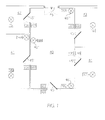
- Figure 1 shows a central room 40, or corridor, which can be entered through the front door 45. Said central room gives access to the side rooms 41, 42, 43 and 44 through the corresponding doors 45', 45", 45''' and 45'''.
- the example also shows a window 46 letting light into the room, which window - as shall be mentioned below - is not strictly necessary for ensuring the supply of the control devices of said room 102, 103, 105, 107 and 109, since the required light energy can also be only artificial light generated by lighting devices 46', 46" and 46'".
- the various control devices are arranged near the doors, on both sides of the walls, so that both the lighting devices of the room one is getting out of and those of the room one is getting into can be controlled.
- Each device is therefore equipped with various buttons, each controlling its own lighting device to which it has been associated.
- a room can have two or more areas requiring separate lighting. It is the case of room 41, in which two lighting apparatus 14A and 14B have been placed; the device 104 will therefore be provided with: a button for controlling the apparatus 14A, a second button for apparatus 14B and a third button for controlling the apparatus of room 40. Still referring to Figure 1, the device 103, placed on the other side of the wall, can either have the same combination of buttons as described for device 104 or only two buttons, one for controlling the lighting apparatus of room 40 and one for controlling only the apparatus 14B of room 41.
- the device is preferably made of plastic.
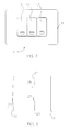
- the levers or control elements are surrounded by the front plate 11 having semitransparent and translucent optical features, such that it has its own color and can be partially got through by room light.
- the material the front plate 11 is made of should also be as transparent as possible to radio waves.
- At least the control device 10 is made at least partially of a material which can be got through at least partially by a light coming from said room, and at the same time at least the control device (and preferably the load piloting device 30, too) are at least partially made of a material at least partially transparent to radio waves.
- the front plate 11 is the exposed portion of the housing, which is closed on the back with a smooth plate 13, so as to be easily applied to a wall or a piece of furniture with biadhesive tape or any other simple fastening system. This feature is particularly advantageous since it allows to greatly simplify cabling and implementation of lighting installations, and to dramatically reduce execution times.
- the thickness of the device can be very small, since inner components are very thin.
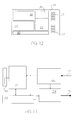
- Figure 4 shows a possible arrangement of the component groups of the device, divided into areas.
- All the electronic and electromechanical components are mounted and welded onto a printed circuit 20.
- Said printed circuit will be placed behind the front plate 11 and the control levers 12, 12' or 12" and fastened onto the base 13 constituting the back side for fastening the device onto a wall.
- the electromechanical contacts 29, 29' and 29" (which are suitably connected at least to the printed circuit 20, as can be seen also in the accompanying figures) can be carried out in several ways: a first example consists in using preloaded spring plates which under pressure put into contact two conductive tracks of the printed circuit. Another possibility consists in using magnetic contacts (or reed-type contacts) which close due to the approach during active periods of a small magnet mounted below the contact levers 12, 12' and 12'', and which are integral with said levers.
- the active period of the device starts, i.e. the period in which the control signal is processed and transmitted, followed by a period in which the confirmation response from the load piloting device 30 is expected, as explained later in further detail.
- the upper portion of the printed circuit houses the photovoltaic modules 21, 21' and 21''.
- these modules comprise a thin film laid onto a ceramic substrate, though any type of photovoltaic cells suiting the object size can be used.
- the selected position should be no limitation at all; the important thing is that said cells have the largest exposed surface as possible, so as to convert and supply a sufficient amount of energy also in unfavorable light conditions.
- the number and type of photovoltaic cells to be used, connected in series one to the other, should be calculated so that the open-circuit voltage supplied by the series in minimum lighting conditions has the same value as or slightly above the voltage of the storage means 24, which store electric energy transformed by photovoltaic cells and give it back in suitable conditions.
- the storage means can comprise at least a battery 24 (which can advantageously be rechargeable) or at least a capacitor.
- the corresponding lighting degree will represent the useful threshold of minimum light intensity for energy storage.
- photovoltaic cells should be calculated depending on the average energy expected to be consumed by the control device, which depends on the frequency with which activations are deemed to be performed. Concerning this, the more the control levers in the device, the more likely the number of activations will be high.
- the calculation of the surface covered by the photovoltaic cells should be made redundantly, also taking into account their conversion efficiency and the fact that the front plate (element 11 in Figure 2) is got through only partially by light.
- the redundancy condition can be easily achieved since the exposed surface of the front plate has a large extension.
- Photovoltaic cells made with technologies characterized by a high conversion efficiency should preferably be used.
- the electric energy coming from the photovoltaic cells should be stored by a suitable element; in the example this element is a ultrathin battery 24 using a solid electrolyte lithium technology.
- the supply means 21, 21' and 21" generate an open-circuit voltage that is at least the same as a corresponding voltage of the storing means 24: if the latter comprise a battery, said voltage will be at least the same as, or slightly higher than, battery voltage, whereas if the latter comprise a capacitor, the higher the voltage supplied by the supply means the more efficient the charge storage on the capacitor.
- said capacity should not be too high since, by increasing its value, beyond increasing battery volume, charge time and self-discharge current increase almost proportionally, thus not improving in any way the operation of the device.
- room brightness consisting in most cases mainly of sunrays, can come from the same artificial light controlled by the device.
- the supply management circuit 25 has the task to manage battery charge, preventing that during dark periods it can partially discharge on photovoltaic cells.
- Another task of said circuit is to switch on and/or off (or in other words, connect and/or disconnect the supply) the downstream electronic circuits 26 and 27, which are in their turn interconnected at least to the electromechanical contacts 29, 29', 29" during rest periods, so as to minimize used current when no activity is requested, i.e. for most of the time.
- the supply management circuit 25 supplies the processing circuit 26 and the radio signal transceiver circuit 27. Supply will go on until the primary processing and coding/decoding circuit 26 communicates to the supply management circuit 25 it has completed both the step of control transmission and the step of confirmation reception.
- the circuits 26 and 27 are thus supplied only for the time strictly required to complete control functions.
- the primary processing and coding/decoding circuit 26 can have different tasks depending on the control modes to be implemented on the piloted load, for instance on the lighting apparatus. Some of these modes could be:
- said circuit 26, preferably comprising a microprocessor and various additional components, should construe the control given by the user and translate it into a code, which the load piloting device 30 should be able to decode.
- the generated code should possibly contain a univocal address, associated to each control element of the device 12, 12' and 12" ( Figure 2), comprising a given number of bits identifying unambiguously the device that has transmitted the radio signal and the actuated control element.
- Each load piloting device 30 will have the task to acquire and store such identifier through a suitable self-learning process, so as to identify the device and the associated control element. Concerning this, said load piloting device 30 should preferably be designed to acquire and store a number of identifiers corresponding to maximum number of control points which might be desired to be associated to each light connection. After decoding the received signals, the load piloting device 30 should only actuate those controls which come from the device control elements and are associated to it and recorded.
- the selected coding mode and issue times for the code constituting the modulating wave of the transmission carrier should be compatible with the occupation of band on which the signal is transmitted.
- the duration of the code to be transmitted should preferably be reduced as much as possible.
- any type of modulation can be chosen for transmitting the signal. However, it should be kept into account that to each type of modulation corresponds a different spectrum of emission of radio frequency (amplitude, frequency, phase etc.), with subsequent modes of occupation of the selected band.
- the transmitter circuit should preferably be designed envisaging the use of active elements (bipolar transistors or field-effect transistors) keeping a high amplification also under conditions of low operating current, and having a cutoff frequency dramatically higher than the one to be used.
- active elements bipolar transistors or field-effect transistors
- the power sent out by the control device should ensure a good quality of reception by the load piloting device 30 at the maximum distance provided for. In most cases, inside buildings a maximum limit of 30 m should be enough.
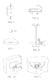
- the load piloting device 30 can have several outer shapes depending on the type of load (or in other words, depending on the electric users, such as for instance the lamps 46, 46', 46" of Figure 1) to be piloted.
- Figures 7, 9 and 11 refer to lighting apparatus, a ceiling lamp (Fig. 7), a floor lamp (Fig. 9) and a wall lamp (Fig. 11) respectively.
- the electronic and electromechanical components of the inner circuits are mounted and welded onto a printed circuit 31.
- Said printed circuit will have a suitable shape so as to be arranged inside corresponding housings.
- the device can be equipped with an input terminal board 32 for the connection to the electric supply network 34, and with an output terminal board 33 to which the load to be piloted 35 will be connected (for sake of simplicity, said terminal boards can be replaced by simple electric cables).
- the main components of the load piloting device 30 can be: a secondary radio transceiver circuit 37 (which as before can be replaced by a simple reception circuit or by a simple transmission circuit); a secondary processing and coding/decoding circuit 38 interconnected to the secondary radio transceiver circuit 37; a power load piloting circuit 39 interconnected at least to the secondary processing and coding/decoding circuit 38 and to be actuated on a load 35.
- the secondary radio transceiver circuit 37, the secondary processing and coding/decoding circuit 38 and the power load piloting circuit 39 take their supply from the electric network 34 by means of a supply circuit 36 obtaining from it the various voltages required for the operation of said electronic circuits.
- the supply circuit 36 can be relatively small.
- the load piloting devices 30 are always active and under watch, so as to receive the radio signal, if present, coming from one of the control devices.
- Each piloting device 30 should save the identifiers corresponding to the control devices associated to it, so that only said devices can communicate with it; all signals coming from other control devices will be ignored.
- the load piloting device 30 After having decoded and identified one of the controls addressed to it, should implement it through the power piloting device 39.
- Said circuit can comprise an electromechanical relay or a solid-state relay based on triac or other semiconductor component, and should be designed so as to tolerate with a given redundancy the current and voltage of the electric load to be piloted.
- the piloting device 30 should send a confirmation signal to the control device that had generated the request.
- control device 10 can check the success of the operation and otherwise it can start an automatic process of control repetition with an algorithm attempting to overcome possible difficulties that might have caused the failure of said operation.
- radio communications between the two main devices constituting the device according to the present invention can be "bi-directional", so as to further increase reliability.
- the base of the control device can have an outer smooth configuration and can thus be installed on the walls of a room with extremely simple and cheap fastening systems.
- this device is particularly suitable for use in lighting installations inside buildings.
Landscapes
- Engineering & Computer Science (AREA)
- Computer Networks & Wireless Communication (AREA)
- Physics & Mathematics (AREA)
- General Physics & Mathematics (AREA)
- Selective Calling Equipment (AREA)
- Control Of Ac Motors In General (AREA)
Applications Claiming Priority (2)
| Application Number | Priority Date | Filing Date | Title |
|---|---|---|---|
| ITVA20030018 ITVA20030018A1 (it) | 2003-06-05 | 2003-06-05 | Sistema elettronico di comando per impianti elettrici basato su onde radio. |
| ITVA20030018 | 2003-06-05 |
Publications (2)
| Publication Number | Publication Date |
|---|---|
| EP1484728A2 true EP1484728A2 (fr) | 2004-12-08 |
| EP1484728A3 EP1484728A3 (fr) | 2006-01-18 |
Family
ID=33156378
Family Applications (1)
| Application Number | Title | Priority Date | Filing Date |
|---|---|---|---|
| EP04102567A Withdrawn EP1484728A3 (fr) | 2003-06-05 | 2004-06-07 | Dispositif de commande pour une installation électrique, en particulier pour installations électriques domestiques |
Country Status (2)
| Country | Link |
|---|---|
| EP (1) | EP1484728A3 (fr) |
| IT (1) | ITVA20030018A1 (fr) |
Cited By (4)
| Publication number | Priority date | Publication date | Assignee | Title |
|---|---|---|---|---|
| EP2020649A1 (fr) * | 2007-08-03 | 2009-02-04 | Mox Motion Gates S.N.C. di Florian Dino & C. | Unité de télécommande portable améliorée |
| FR2929779A1 (fr) * | 2008-04-07 | 2009-10-09 | Somfy Sas | Emetteur d'ordres autonome pour installation domotique |
| FR2952229A1 (fr) * | 2009-11-04 | 2011-05-06 | Somfy Sas | Dispositif de commande et/ou d'information a distance de l'etat de produits de type domotique, comprenant un panneau photovoltaique annulaire |
| GB2499183A (en) * | 2012-01-05 | 2013-08-14 | Sean Linden | Solar wireless remote control |
Family Cites Families (3)
| Publication number | Priority date | Publication date | Assignee | Title |
|---|---|---|---|---|
| GB2174222B (en) * | 1985-04-27 | 1988-09-21 | Peter Stanley Phillips | Remote operation of an electrical light switch |
| FR2606912B1 (fr) * | 1986-11-14 | 1989-03-17 | Pierron Sa | Dispositif formant emetteur a cellule photovoltaique |
| US20010033243A1 (en) * | 2000-03-15 | 2001-10-25 | Harris Glen Mclean | Online remote control configuration system |
-
2003
- 2003-06-05 IT ITVA20030018 patent/ITVA20030018A1/it unknown
-
2004
- 2004-06-07 EP EP04102567A patent/EP1484728A3/fr not_active Withdrawn
Non-Patent Citations (1)
| Title |
|---|
| None * |
Cited By (6)
| Publication number | Priority date | Publication date | Assignee | Title |
|---|---|---|---|---|
| EP2020649A1 (fr) * | 2007-08-03 | 2009-02-04 | Mox Motion Gates S.N.C. di Florian Dino & C. | Unité de télécommande portable améliorée |
| FR2929779A1 (fr) * | 2008-04-07 | 2009-10-09 | Somfy Sas | Emetteur d'ordres autonome pour installation domotique |
| EP2109086A1 (fr) * | 2008-04-07 | 2009-10-14 | Somfy SAS | Emetteur d'ordres autonome pour installation domotique. |
| FR2952229A1 (fr) * | 2009-11-04 | 2011-05-06 | Somfy Sas | Dispositif de commande et/ou d'information a distance de l'etat de produits de type domotique, comprenant un panneau photovoltaique annulaire |
| EP2320402A3 (fr) * | 2009-11-04 | 2012-09-12 | Somfy SAS | Dispositif de commande et/ou d'obtention d'information à distance de l'état de produits de type domotique, comprenant un panneau photovoltaïque annulaire |
| GB2499183A (en) * | 2012-01-05 | 2013-08-14 | Sean Linden | Solar wireless remote control |
Also Published As
| Publication number | Publication date |
|---|---|
| ITVA20030018A1 (it) | 2004-12-06 |
| EP1484728A3 (fr) | 2006-01-18 |
Similar Documents
| Publication | Publication Date | Title |
|---|---|---|
| Han et al. | Remote-controllable and energy-saving room architecture based on ZigBee communication | |
| US7230532B2 (en) | Wireless sensor system | |
| EP1958486B1 (fr) | Systeme et procede de charge de dispositif de commande de systeme d'eclairage | |
| US20080094189A1 (en) | Repeater unit with flourescent ballast | |
| CN112885070B (zh) | 超微功耗信号发射装置及其应用 | |
| CN204741606U (zh) | 一种智能单火线开关 | |
| JP2002330095A (ja) | 基地局、基地局の制御方法及び移動通信システム | |
| CN117411339A (zh) | 具有灵活端口的多用途逆变器 | |
| EP3772157A1 (fr) | Dispositif de commutation | |
| CN108377020B (zh) | 一种激光无线充电的系统 | |
| EP1484728A2 (fr) | Dispositif de commande pour une installation électrique, en particulier pour installations électriques domestiques | |
| CA2598463C (fr) | Dispositif electronique sans fil destine a des connexion et deconnexion automatiques d'une alimentation electrique et procede associe | |
| RU2560124C2 (ru) | Электрическая инсталляционная система | |
| CN202794902U (zh) | 一种智能开关系统 | |
| KR101052823B1 (ko) | 엘이디 조명 제어 시스템 | |
| US20180023774A1 (en) | Photovoltaic system and method for utilizing energy of light emitted by light fixture | |
| CN222630756U (zh) | 基于自发电的无线呼梯设备 | |
| CN107544445A (zh) | 一种智能开关及智能家居系统 | |
| CN201876684U (zh) | 一种用于对强电组件进行控制的无线控制开关 | |
| CN212811660U (zh) | 单火开关双控系统 | |
| CN218867923U (zh) | 一种智能用电管理器 | |
| CN216930376U (zh) | 一种电梯井道灯控制系统 | |
| CN212573059U (zh) | 一种智能灯光系统 | |
| CN200980071Y (zh) | 智能型无线遥控照明系统网络控制开关总成 | |
| CN109616346B (zh) | 一种墙壁开关 |
Legal Events
| Date | Code | Title | Description |
|---|---|---|---|
| PUAI | Public reference made under article 153(3) epc to a published international application that has entered the european phase |
Free format text: ORIGINAL CODE: 0009012 |
|
| AK | Designated contracting states |
Kind code of ref document: A2 Designated state(s): AT BE BG CH CY CZ DE DK EE ES FI FR GB GR HU IE IT LI LU MC NL PL PT RO SE SI SK TR |
|
| AX | Request for extension of the european patent |
Extension state: AL HR LT LV MK |
|
| PUAL | Search report despatched |
Free format text: ORIGINAL CODE: 0009013 |
|
| AK | Designated contracting states |
Kind code of ref document: A3 Designated state(s): AT BE BG CH CY CZ DE DK EE ES FI FR GB GR HU IE IT LI LU MC NL PL PT RO SE SI SK TR |
|
| AX | Request for extension of the european patent |
Extension state: AL HR LT LV MK |
|
| 17P | Request for examination filed |
Effective date: 20060331 |
|
| AKX | Designation fees paid |
Designated state(s): AT BE BG CH CY CZ DE DK EE ES FI FR GB GR HU IE IT LI LU MC NL PL PT RO SE SI SK TR |
|
| 17Q | First examination report despatched |
Effective date: 20061120 |
|
| STAA | Information on the status of an ep patent application or granted ep patent |
Free format text: STATUS: THE APPLICATION IS DEEMED TO BE WITHDRAWN |
|
| 18D | Application deemed to be withdrawn |
Effective date: 20070601 |