EP1484775A1 - Moyens de couplage pour des éléments tournants d'un interrupteur - Google Patents
Moyens de couplage pour des éléments tournants d'un interrupteur Download PDFInfo
- Publication number
- EP1484775A1 EP1484775A1 EP03012803A EP03012803A EP1484775A1 EP 1484775 A1 EP1484775 A1 EP 1484775A1 EP 03012803 A EP03012803 A EP 03012803A EP 03012803 A EP03012803 A EP 03012803A EP 1484775 A1 EP1484775 A1 EP 1484775A1
- Authority
- EP
- European Patent Office
- Prior art keywords
- coupling
- coupling device
- drive
- switching element
- curvature
- Prior art date
- Legal status (The legal status is an assumption and is not a legal conclusion. Google has not performed a legal analysis and makes no representation as to the accuracy of the status listed.)
- Withdrawn
Links
- 230000008878 coupling Effects 0.000 title claims abstract description 156
- 238000010168 coupling process Methods 0.000 title claims abstract description 156
- 238000005859 coupling reaction Methods 0.000 title claims abstract description 156
- 230000005540 biological transmission Effects 0.000 claims abstract description 41
- 238000006243 chemical reaction Methods 0.000 abstract 1
- 230000033001 locomotion Effects 0.000 description 19
- 238000000034 method Methods 0.000 description 9
- 230000008569 process Effects 0.000 description 9
- 238000013519 translation Methods 0.000 description 8
- 230000006835 compression Effects 0.000 description 3
- 238000007906 compression Methods 0.000 description 3
- 238000010586 diagram Methods 0.000 description 3
- 230000009471 action Effects 0.000 description 2
- 238000004146 energy storage Methods 0.000 description 2
- 230000008901 benefit Effects 0.000 description 1
- 230000008859 change Effects 0.000 description 1
- 238000013461 design Methods 0.000 description 1
- 238000011161 development Methods 0.000 description 1
- 230000004069 differentiation Effects 0.000 description 1
- 238000006073 displacement reaction Methods 0.000 description 1
- 238000009434 installation Methods 0.000 description 1
- 239000000725 suspension Substances 0.000 description 1
- 238000012549 training Methods 0.000 description 1
- 230000007704 transition Effects 0.000 description 1
Images


Classifications
-
- H—ELECTRICITY
- H01—ELECTRIC ELEMENTS
- H01H—ELECTRIC SWITCHES; RELAYS; SELECTORS; EMERGENCY PROTECTIVE DEVICES
- H01H9/00—Details of switching devices, not covered by groups H01H1/00 - H01H7/00
- H01H9/20—Interlocking, locking, or latching mechanisms
-
- H—ELECTRICITY
- H01—ELECTRIC ELEMENTS
- H01H—ELECTRIC SWITCHES; RELAYS; SELECTORS; EMERGENCY PROTECTIVE DEVICES
- H01H3/00—Mechanisms for operating contacts
- H01H3/32—Driving mechanisms, i.e. for transmitting driving force to the contacts
-
- H—ELECTRICITY
- H01—ELECTRIC ELEMENTS
- H01H—ELECTRIC SWITCHES; RELAYS; SELECTORS; EMERGENCY PROTECTIVE DEVICES
- H01H71/00—Details of the protective switches or relays covered by groups H01H73/00 - H01H83/00
- H01H71/10—Operating or release mechanisms
- H01H71/1009—Interconnected mechanisms
-
- H—ELECTRICITY
- H01—ELECTRIC ELEMENTS
- H01H—ELECTRIC SWITCHES; RELAYS; SELECTORS; EMERGENCY PROTECTIVE DEVICES
- H01H71/00—Details of the protective switches or relays covered by groups H01H73/00 - H01H83/00
- H01H71/10—Operating or release mechanisms
- H01H71/66—Power reset mechanisms
- H01H71/70—Power reset mechanisms actuated by electric motor
Definitions
- the invention relates to a coupling device for devices rotatable switching elements, especially for modular devices.
- a modular device that can be snapped onto a DIN rail with a rotatable, also known as a switching knob Switching element is known for example from DE 197 24 945 A1.
- a drive can optionally be used for a DIN rail mounted device be provided by means of a remote drive.
- a remote operator for a circuit breaker is, for example, from the DE 37 10 520 A1 known, both the remote drive and the circuit breaker is also designed as a modular installation device are and each a rotatable also referred to as a handle Have switching element.
- a driver connecting them is provided for coupling the two switching elements.
- a such coupling requires that the switching elements a common geometric axis of rotation are pivotable.
- the invention has for its object a constructive simple and space-saving coupling device for devices specify with rotatable switching elements, the to coupling switching elements spaced parallel to each other Axes of rotation are pivotable.
- the coupling device serves to couple a rotatable drive switching element a first device with a rotatable output switching element of a second device.
- drive switching element and “output switching element” are for linguistic Differentiation between the two switching elements selected and implied not necessarily a function specification.
- each Switching element is from a first position, in particular one Off position, in a second position, especially one On position, usually with an actuation angle of less than 180 °, swiveling.
- the switching elements is a translation element provided, which is rigid overall and three coupling elements having:
- a first coupling element referred to as the drive coupling element is with the first switching element by means of a rotary or Swivel connection can be coupled.
- the drive coupling element For this purpose, preferably has a coupling axis which, when actuated of the drive switching element movable on an arc is.
- the first coupling element can be easily be designed as a socket into which a drive pin can be inserted is, which can be connected to the drive switching element at the same time is.
- An output coupling element is provided as the second coupling element, which is preferred with the second switching element can be coupled by means of a sliding surface.
- the distance the coupling axis of the first coupling element to the axis of rotation of the Drive switching element is constant, the distance is the Sliding surface of the second coupling element to the axis of rotation of the output switching element variable.
- a transmission coupling element is the third coupling element provided which is slidable along a guideway is.
- the guideway can either be part of one of the coupling devices, in particular the device with the output switching element, or be part of the coupling device.
- the coupling device is thus particularly compact, with no further transmission between the devices to be coupled is required.
- the coupling device a spring element, which is pivotable on the transmission element is stored.
- the transmission element a preferred between the drive coupling element and the Transmission coupling element arranged spring bearing element, on which one side of the spring element is held.
- the other side of the spring element is on one relative to the Axes of rotation of the switching elements fixed bearing point, in particular in the housing of the second including the output switching element Device, storable.
- the spring element serves as an energy store, which absorbs energy during the switching process and emits.
- the spring element when pivoting the Drive switching element from the first position to the second Position initially cocked and before reaching the second position relaxed. This training is in particular together with a variable transmission ratio of the coupling device advantageous.
- the Guideway preferably on several areas of curvature. there corresponds to the direction of curvature of the guideway in one first area of curvature of the curvature of a circle, in which arranged the axis of rotation of the output switching element is.
- a second which adjoins the first area of curvature
- the curvature area shows the opposite Curvature on.
- the first area of curvature which is the initial relatively slow movement of the output switching element is assigned to the first position, in particular Facing from position, and has a radius of curvature, which is larger than a radius of curvature of the second region of curvature.
- the radius of curvature can be within both areas of curvature vary.
- the second area of curvature optionally includes towards the second position non-curved linear guide area. In this area the angular velocity of the output switching element, after the one optionally arranged in the second in the second device Contact is already closed, again less.
- While for power transmission from the drive switching element the output switching element during the switching process from the first to the second position, especially when switching on, a Action of the sliding surface of the output coupling element the second switching element is provided is in reverse Switching direction, i.e. when the drive switching element is actuated from the second position to the first position, preferably an action of the spring element on the second Switching element, i.e. the output switching element is provided.
- the Coupling device is due to this double function of the spring element particularly material-saving. On special this double function of the spring element is simple realizable if it has an L-shaped basic shape, wherein the output switching element has an actuating lever, the one in the second position at least approximately on one the L-leg of the spring element rests.
- the drive switching element at Switching off initially without coupling to the output switching element can be pivoted, i.e. a clearance angle has this function by the type of storage of the Spring element can be realized.
- the spring element is preferred on the translation element, for example by means of a tab, slidably mounted.
- the coupling device has a frame in which the transmission element is movable is stored. This frame is preferred on the second device, i.e. the device, the switching element in general is driven with the aid of the first device.
- the guideway for the transmission coupling element is preferably formed by the frame.
- the Frame preferably an arcuate drive guide track on, along that with the drive switching element pivotable drive coupling element is displaceable.
- the output coupling element is just like that Spring element guided between the long sides of the frame.
- the transmission element has a cross-section, i.e. in line of sight along the axes of rotation of the switching elements, preferred a triangular basic shape, with the coupling elements at least are arranged approximately at the corners of the triangle. While the drive and transmission coupling element is preferred are socket or pin-shaped, the output coupling element preferably in the manner of an operating tongue shaped. This connects two within the frame sliding cheeks of the transmission element, the output switching element can intervene between the cheeks. The with the output switching element interacting sliding surface the output coupling element is preferably designed such that a contact point, which is used to contact the output switching element is provided when the drive switching element is actuated from the first position to the second position increasingly removed from the coupling axis.
- the output coupling element is in relation to a connecting line between the drive coupling element and the transmission coupling element preferably positioned such that a perpendicular bisector the essentially flat sliding surface the connecting line and / or at least approximately the transmission coupling element cuts.
- the frame of the coupling device is preferred for mechanical Connection with the side, i.e. in the axial direction of the Axes offset, adjacent first, the drive switching element having provided device.
- the frame points to this at least one snap connector.
- Preferably is at least one positive snap element, i.e. on highlighted snap element and at least one negative snap element, i.e. one designed as a recess or recess Snap element provided.
- the advantage of the invention is in particular that two switching elements can be coupled with different axes of rotation are, whereby a variable transmission ratio is established is and the coupling in the transverse direction of the to be connected Devices, i.e. in the direction of the axes of rotation, no additional Space needed.
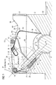
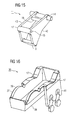
- FIGS 1 to 8 The mode of operation of a for coupling a first device 1 coupling device 3 provided with a second device 2 is explained below with reference to FIGS 1 to 8.
- Actuation toggle At the first Device 1 is a remote operator with a motor-driven as drive switching element 4 Actuation toggle, which can also be operated manually and as the only part of the first device 1 in the illustrations is visible.
- a handle 5 of the drive switching element 4 is by an actuation angle ⁇ of 100 ° (FIG 7) pivotable.
- the motorized swivel movement is in 1.2 s completed, corresponding to a swivel speed of 83 ° / s.
- the second device 2 has one as an output switching element 6 designated operating knob with an operating lever 7, which can be rotated by a swivel angle ⁇ of 90 ° is.
- the second device 2 in the exemplary embodiment a FI switch, is for a pivoting movement of the output switching element 6 in 0.5 seconds, i.e. a swing speed of 180 ° / s, designed.
- the requirements for the actuation speed distinguish the output switching element 6 differ significantly from the conditions of the first device 1 with a much lower swivel speed.
- the coupling device 3 To the first device 1 for driving the output switching element 6 of the second device 2, the coupling device 3 in a manner explained in more detail below variable gear ratio.
- the drive switching element 4 is about a first axis of rotation 8 rotatable, while the output switching element 6 by a second, Rotational axis 9 offset parallel to the first rotational axis is rotatable.
- the second device 2 the housing 10 in the Representations that are visible in sections are relative to first device 1 offset in the direction of the axes of rotation 8.9 this adjacent.
- Both devices 1, 2 are on a top-hat rail snap-on modular devices, wherein the second axis of rotation 9 of the second device 2 less from the DIN rail is spaced as the first axis of rotation 8 of the first Device 1.
- the coupling device 3 put on the second device 2 is the coupling device 3 put on. Incidentally, the devices 1,2 are approximately the same contours.
- the coupling device 3 has a transmission element 11 a triangular basic shape, at least approximately in the corners of which each have a coupling element 12, 13, 14 arranged is.
- the first, also referred to as a drive coupling element Coupling element 12 has a coupling axis 15, along the one Drive pin 16 is arranged, which is a connection between the coupling device 3 and the drive switching element 4 manufactures.
- the drive coupling element 12 is therefore always from the first axis of rotation 8 constantly spaced, one Pivotal movement between the drive switching element 4 and the Translation element 11 is possible.
- the second coupling element 13 is an approximately tongue-shaped output coupling element trained to operate the Actuating lever 7 of the output switching element 6 is provided is.
- the third coupling element 14 is also used as a transmission coupling element designated and is along a guideway 17th slidably mounted.
- the translation element 11 also has a bolt-shaped Spring position element 18 on which a spring element 19 by means of a bracket 20 pivotable and to a certain extent is also slidably mounted. That as in cross section L-shaped leaf spring formed spring element 19 is on one Support point 21 stored in the housing 10.
- FIG. 1 shows the coupling device 3 and the switching elements 4,6 in a first position, namely the off position of the devices 1.2.
- a sliding surface facing the operating lever 7 22 of the output coupling element 13 is not in contact with the output switching element 6.
- the sliding surface 22 is essentially flat and so relative to that Drive coupling element 12 and the transmission coupling element 14 aligned that a perpendicular bisector 23 of the sliding surface 22 a connecting line 24 between the drive coupling element 12 and the transmission coupling element 14 intersects.
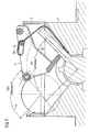
- the given gear ratio also represents a reliable one Start the pivoting movement of the output switching element 6 sure.
- the curvature inside of the first curvature region 27 corresponds to the curvature of one Circle in which the second axis of rotation 9 is arranged is.
- the at the beginning of the first area of curvature, i.e. in one Area in which the transmission coupling element 14 in the off position (FIG 1), almost parallel to one Upper housing edge 28 of the second device 2 extending guideway 17 thus falls in its further course, i.e. in Direction to the on position, towards the top edge of the housing 28.
- the spring element 19 during the displacement of the transmission coupling element 14 along the first curvature region 27 of the Guide track 17 compressed.
- the spring element 19 is as Compression spring formed, with a lifting of the transmission coupling element 14 from the guideway 17 through one here Cover element, not shown, is prevented. Through the Compression of the spring element 19 is thus in this energy saved. This energy storage takes place in one first movement phase of the translation element 11 takes place, while the output switching element 6 slowly, but with increasing Speed is moved.
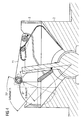
- the transmission element passes through in the direction of the on position 14, as can be seen from FIGS. 4 to 7, initially one second curvature area 29 and then a linear guide area 30.
- the second curvature region 29 is in the Comparison to the first curvature region 27 in the opposite Curved direction and has a radius of curvature R2, which is less than the radius of curvature R1 within the first region of curvature 27. While the transmission coupling element 14 passes through the second region of curvature 29 occurs the maximum compression and thus the maximum energy storage in the spring element 19. Then, especially in Linear guide area 30, the spring element 19 is again relaxed.
- the guideway 17 rises within a part of the second curvature region 29 and within the subsequent one Linear guide area 30 relative to the upper edge of the housing 28, with the output coupling element at the same time 13, which the actuating lever 7 now with one to the flat area of the sliding surface 22 adjoining rounding area 31 contacted, moved to the second axis of rotation 8 becomes. This accelerates the rotary movement of the output switching element 6. This accelerated movement will supported by the relaxation of the spring element 19th
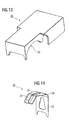
- FIGS. 9 to 16 show the coupling device 3 or parts this in different perspectives.
- the Coupling device 3 has a frame 35 in which the transmission element 11 including the spring element 19th is movably mounted and covered by a cover cap 36 is.
- One guideway 17 is on a first one Long side 37 and a second long side 38 of the frame 35, which faces the first device 1, not shown, educated.
- the design of the translation element 11 is particular can be seen from FIG.
- Two approximately triangular cheeks 40 are connected by the first coupling element designed as a sleeve 12, the tongue-shaped output coupling element 13, the Transmission coupling element 14 designed as a guide pin and the pin-shaped spring bearing element 18.
- the Cheeks 40 which are parallel to the coupling device 3 Longitudinal sides 37,38 are arranged, the actuating lever 7 engage the output switching element 6.
- the coupling device 3 is by means of a snap connection element 41 connectable to the first device 1.
- the snap connector 41 each has two positive snap elements 42 and negative snap elements 43, which are suitable shaped snap elements on the first device 1 correspond.
- This multiple engagement of the coupling device 3 on the first device 1 is a stable, non-rotating Bracket reached.
- the coupling device 3 in lateral direction, i.e. in the direction of extension of the axes of rotation 8.9 and the drive pin 16 practically none Space requirements.
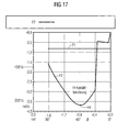
- the diagram shown in FIG. 17 shows the relationship between the swivel angle ⁇ of the output switching element 6 of the second device 2 and the actuation speed F1 of the first device 1, namely remote drive and the Swing speed F2 of the second device 2, namely FI switch.
- the off position corresponds to a swivel angle ⁇ of 0 °, the on position a swivel angle ⁇ of 90 °.
- the switch-on process is therefore from right to left in the diagram consider.
- the amounts of the speeds decrease down to.
- the actuation speed F1 of the drive switching element 4 is during the entire shift constant at just under minus 1 rad per second.
- the position of the Output switching element 6 at the beginning of the switching process, accordingly 1, is at a swivel angle ⁇ of 0 ° and at given a swing speed F2 of 0 rad per second.
- the initially jagged course of the swivel speed results from the shift of investment points 25, 26 at the beginning the pivoting process.
- the swivel speed F2 has a maximum of 45 ° (in the illustration due to negative angular velocities below).
- In the area of the maximum 44 a contact in the second device 2.
- With further swiveling movement of the output switching element 6 and closed contact slows down the swing speed F2 again. It is crucial high switching speed during contact contact, which minimizes sparking.
Landscapes
- Transmission Devices (AREA)
- Railway Tracks (AREA)
Priority Applications (7)
| Application Number | Priority Date | Filing Date | Title |
|---|---|---|---|
| EP03012803A EP1484775A1 (fr) | 2003-06-05 | 2003-06-05 | Moyens de couplage pour des éléments tournants d'un interrupteur |
| EP04728566A EP1629512B1 (fr) | 2003-06-05 | 2004-04-21 | Dispositif de couplage pour appareils munis d'elements de commutation rotatifs |
| DE502004006780T DE502004006780D1 (de) | 2003-06-05 | 2004-04-21 | Koppelvorrichtung für geräte mit drehbaren schaltelementen |
| ES04728566T ES2300764T3 (es) | 2003-06-05 | 2004-04-21 | Dispositivo de acoplamiento para aparatos con elementos de conexion que pueden girar. |
| CNB200480010810XA CN100559528C (zh) | 2003-06-05 | 2004-04-21 | 用在分别带有可旋转的开关元件的各设备之间的耦合器 |
| BRPI0411015-3A BRPI0411015A (pt) | 2003-06-05 | 2004-04-21 | dispositivo de acoplamento para aparelhos com elementos de comutação rotativos |
| PCT/EP2004/004234 WO2004109731A1 (fr) | 2003-06-05 | 2004-04-21 | Dispositif de couplage pour appareils munis d'elements de commutation rotatifs |
Applications Claiming Priority (1)
| Application Number | Priority Date | Filing Date | Title |
|---|---|---|---|
| EP03012803A EP1484775A1 (fr) | 2003-06-05 | 2003-06-05 | Moyens de couplage pour des éléments tournants d'un interrupteur |
Publications (1)
| Publication Number | Publication Date |
|---|---|
| EP1484775A1 true EP1484775A1 (fr) | 2004-12-08 |
Family
ID=33155166
Family Applications (2)
| Application Number | Title | Priority Date | Filing Date |
|---|---|---|---|
| EP03012803A Withdrawn EP1484775A1 (fr) | 2003-06-05 | 2003-06-05 | Moyens de couplage pour des éléments tournants d'un interrupteur |
| EP04728566A Expired - Lifetime EP1629512B1 (fr) | 2003-06-05 | 2004-04-21 | Dispositif de couplage pour appareils munis d'elements de commutation rotatifs |
Family Applications After (1)
| Application Number | Title | Priority Date | Filing Date |
|---|---|---|---|
| EP04728566A Expired - Lifetime EP1629512B1 (fr) | 2003-06-05 | 2004-04-21 | Dispositif de couplage pour appareils munis d'elements de commutation rotatifs |
Country Status (6)
| Country | Link |
|---|---|
| EP (2) | EP1484775A1 (fr) |
| CN (1) | CN100559528C (fr) |
| BR (1) | BRPI0411015A (fr) |
| DE (1) | DE502004006780D1 (fr) |
| ES (1) | ES2300764T3 (fr) |
| WO (1) | WO2004109731A1 (fr) |
Families Citing this family (1)
| Publication number | Priority date | Publication date | Assignee | Title |
|---|---|---|---|---|
| CN116230460B (zh) * | 2023-05-06 | 2023-07-07 | 广东米勒电气有限公司 | 一种断路器快速自动合闸机构及安装有该机构的断路器 |
Citations (4)
| Publication number | Priority date | Publication date | Assignee | Title |
|---|---|---|---|---|
| DE3710520A1 (de) * | 1987-03-30 | 1988-10-13 | Siemens Ag | Fernantrieb fuer schutzschalter |
| US5693923A (en) * | 1996-04-15 | 1997-12-02 | Eaton Corporation | Motor operator for electrical switches |
| US6326870B1 (en) * | 1999-08-26 | 2001-12-04 | General Electric Company | Remote operating apparatus and method for a circuit breaker handle |
| FR2817078A1 (fr) * | 2000-11-21 | 2002-05-24 | Hager Electro | Dispositif de commande a distance pour appareillage modulaire de protection |
Family Cites Families (1)
| Publication number | Priority date | Publication date | Assignee | Title |
|---|---|---|---|---|
| US5867082A (en) * | 1995-06-02 | 1999-02-02 | Duraswitch, Inc. | Switch with magnetically-coupled armature |
-
2003
- 2003-06-05 EP EP03012803A patent/EP1484775A1/fr not_active Withdrawn
-
2004
- 2004-04-21 CN CNB200480010810XA patent/CN100559528C/zh not_active Expired - Fee Related
- 2004-04-21 EP EP04728566A patent/EP1629512B1/fr not_active Expired - Lifetime
- 2004-04-21 ES ES04728566T patent/ES2300764T3/es not_active Expired - Lifetime
- 2004-04-21 BR BRPI0411015-3A patent/BRPI0411015A/pt not_active IP Right Cessation
- 2004-04-21 WO PCT/EP2004/004234 patent/WO2004109731A1/fr not_active Ceased
- 2004-04-21 DE DE502004006780T patent/DE502004006780D1/de not_active Expired - Lifetime
Patent Citations (4)
| Publication number | Priority date | Publication date | Assignee | Title |
|---|---|---|---|---|
| DE3710520A1 (de) * | 1987-03-30 | 1988-10-13 | Siemens Ag | Fernantrieb fuer schutzschalter |
| US5693923A (en) * | 1996-04-15 | 1997-12-02 | Eaton Corporation | Motor operator for electrical switches |
| US6326870B1 (en) * | 1999-08-26 | 2001-12-04 | General Electric Company | Remote operating apparatus and method for a circuit breaker handle |
| FR2817078A1 (fr) * | 2000-11-21 | 2002-05-24 | Hager Electro | Dispositif de commande a distance pour appareillage modulaire de protection |
Also Published As
| Publication number | Publication date |
|---|---|
| CN1777967A (zh) | 2006-05-24 |
| CN100559528C (zh) | 2009-11-11 |
| WO2004109731A1 (fr) | 2004-12-16 |
| DE502004006780D1 (de) | 2008-05-21 |
| EP1629512B1 (fr) | 2008-04-09 |
| BRPI0411015A (pt) | 2006-07-04 |
| ES2300764T3 (es) | 2008-06-16 |
| EP1629512A1 (fr) | 2006-03-01 |
Similar Documents
| Publication | Publication Date | Title |
|---|---|---|
| EP1932625B1 (fr) | Appareil d'outillage manuel électrique | |
| DE2825023C2 (fr) | ||
| DE3243123C2 (de) | Fensterheber, insbesondere für Kraftfahrzeuge | |
| EP0241798A2 (fr) | Pince pour sertissage des bornes de câbles, des connecteurs de câbles, et semblables avec des connecteurs électriques, des guides d'ondes etc... | |
| DE102004005014A1 (de) | Elektrische Klemmvorrichtung | |
| EP0397294B1 (fr) | Mécanisme de commande pour un interrupteur à vide avec un ressort de contact | |
| EP3439011A1 (fr) | Appareil électrique | |
| DE19758288B4 (de) | Verfahren und Vorrichtung zur drehrichtungsgekoppelten Rückstellung eines Schalters | |
| WO2003073003A1 (fr) | Appareil menager | |
| DE3117040C2 (de) | Betätigungsvorrichtung für ein Kipp- und Schiebedach eines Kraftfahrzeugs oder dergleichen | |
| EP2347859A1 (fr) | Mécanisme pas à pas pour un outil de serrage et/ou d'écartement et outil de serrage et/ou d'écartement | |
| WO2008068135A1 (fr) | Transmission pour commutateur électrique de puissance | |
| DE102005001818A1 (de) | Schaltvorrichtung für ein Automatikgetriebe eines Kraftfahrzeuges | |
| EP0750837A1 (fr) | Taille-haie | |
| DE10015596A1 (de) | Schloßanordnung mit einer motorisch antreibbaren Zuziehhilfe | |
| DE3512665A1 (de) | Elektrischer schalter | |
| DE69834859T2 (de) | Elektrischer Einheit mit Betätigungseinrichtung für einen Schutzschalter | |
| EP1484775A1 (fr) | Moyens de couplage pour des éléments tournants d'un interrupteur | |
| EP0782510B1 (fr) | Commutateur monte sur la colonne de direction, servant d'organe de changement de vitesses avec possibilite de fixation en position neutre | |
| EP1267240A1 (fr) | Changement de vitesse pour une boíte de vitesses manuelle d'un véhicule automobile | |
| DE3627234A1 (de) | Fensterheber, insbesondere fuer kraftfahrzeuge | |
| DE10128340A1 (de) | Betätigungseinrichtung für eine gesteuerte Kraftfahrzeugkupplung | |
| EP0157186B1 (fr) | Commutateur à curseur verrouillable | |
| EP1439277B1 (fr) | Charnière | |
| DE3419168A1 (de) | Sperrvorrichtung fuer einen handbetaetigten gangwaehler |
Legal Events
| Date | Code | Title | Description |
|---|---|---|---|
| PUAI | Public reference made under article 153(3) epc to a published international application that has entered the european phase |
Free format text: ORIGINAL CODE: 0009012 |
|
| AK | Designated contracting states |
Kind code of ref document: A1 Designated state(s): AT BE BG CH CY CZ DE DK EE ES FI FR GB GR HU IE IT LI LU MC NL PT RO SE SI SK TR |
|
| AX | Request for extension of the european patent |
Extension state: AL LT LV MK |
|
| AKX | Designation fees paid | ||
| REG | Reference to a national code |
Ref country code: DE Ref legal event code: 8566 |
|
| STAA | Information on the status of an ep patent application or granted ep patent |
Free format text: STATUS: THE APPLICATION IS DEEMED TO BE WITHDRAWN |
|
| 18D | Application deemed to be withdrawn |
Effective date: 20050609 |