EP1484852A2 - Optisches Freiraum-Kommunikationssystem - Google Patents
Optisches Freiraum-Kommunikationssystem Download PDFInfo
- Publication number
- EP1484852A2 EP1484852A2 EP04253116A EP04253116A EP1484852A2 EP 1484852 A2 EP1484852 A2 EP 1484852A2 EP 04253116 A EP04253116 A EP 04253116A EP 04253116 A EP04253116 A EP 04253116A EP 1484852 A2 EP1484852 A2 EP 1484852A2
- Authority
- EP
- European Patent Office
- Prior art keywords
- optical
- antenna
- terminal
- aperture
- apertures
- Prior art date
- Legal status (The legal status is an assumption and is not a legal conclusion. Google has not performed a legal analysis and makes no representation as to the accuracy of the status listed.)
- Granted
Links
Images



Classifications
-
- H—ELECTRICITY
- H04—ELECTRIC COMMUNICATION TECHNIQUE
- H04B—TRANSMISSION
- H04B10/00—Transmission systems employing electromagnetic waves other than radio-waves, e.g. infrared, visible or ultraviolet light, or employing corpuscular radiation, e.g. quantum communication
- H04B10/11—Arrangements specific to free-space transmission, i.e. transmission through air or vacuum
- H04B10/112—Line-of-sight transmission over an extended range
- H04B10/1123—Bidirectional transmission
- H04B10/1125—Bidirectional transmission using a single common optical path
Definitions
- the present subject matter relates to free-space optical (FSO) communication systems and may be used for two-way information exchange between remote objects without using electrical wires and/or optical fibers, including the case of multiple objects taking part in an information exchange.
- FSO free-space optical
- Free-space optical communication systems usually consist of two terminals comprising at least one light source and a receiver, coupled with transmit telescope(s) and a receive telescope, respectively.
- FSO communication systems wherein the terminals comprise a light source and an optical receiver connected to corresponding transmit and receive telescopes by optical fibers (this is so-called fiber-based FSO systems).
- fiber-based FSO systems One of advantages of fiber-based FSO systems is that the use of optical fibers allows, if necessary, to place the optical system apart from signal source(s) and a receiver (US Patent No 4,960,315).
- Such fiber-based FSO designs provide flexibility in positioning signal source(s) and a receiver relative to optical antennas (transmit and receive telescopes). This makes them less sensitive to thermal and mechanical perturbations and more compact (see USP 4,960,315).
- a disadvantage of the device proposed in USP 4,960,315 is that a separate telescope is necessary for every light source and for optical receiver.
- the approach based on coupling multiple fibers into one transmit telescope generally causes optical power losses and occasional dropping of some of the transmit channels, as images of the fibers light emitting facets built by the telescope objective lens at the location of a remote receive terminal, do not overlap on the receive aperture, so that some of them may be missed by the aperture.
- the fibers were proposed to be coupled into the telescope through a tapered fiber bundle.
- the fiber bundle consists of fibers with reduced the fiber core-to-core spacing. This puts images of the fibers' output cross-sections built by the telescope lens closer to each other, making it easier to capture the images of such cross-sections with the receive aperture of a remote receive terminal.
- a possible solution for coupling receive and transmit FSO channels with the same telescope is to provide optical coupling of a proximal end of a fiber both with the transmitter(s) and the receiver(s) of optical signals. A distal end of this fiber is thereby optically coupled with the optical antenna providing transmission and reception of optical signals via the free space.
- a transmit/receive fiberoptic communication devise comprising a radiation source and a photodetector provided with a common lens system and with means for separation of receive and transmit optical beams having different carrier frequencies.
- the channel discrimination means is implemented as two optical filters separated by a lens system providing optical coupling of the light source and photodetector with the end of a single optical fiber (see JP PN 10-010354).
- a lens system providing optical coupling of the light source and photodetector with the end of a single optical fiber (see JP PN 10-010354).
- Such a device is expensive in manufacturing because of the need for wavelength division optical components and auxiliary optics at the fiber end that optically connects to the light sources and photodetectors.
- Goals of the disclosed free-space optical communication system include simplification of design, minimization of cost, and increasing of the number of light sources and photodetectors transmitting and receiving the optical signals through a shared optical antenna.
- the free-space optical communication system comprises two transmit/receive terminals, where at least one of them comprises at least one photodetector and one light source optically coupled with a common transmit/receive optical antenna.
- the first terminal optical antenna is implemented so that it forms point spread functions of points located at the first terminal light sources output apertures so that they overlap in the area where the second terminal transmit/receive antenna aperture is located.
- the first terminal antenna is implemented as a focusing lens, while the apertures of the first terminal sources and photodetectors are displaced along the optical axes of sources and, correspondingly, photodetectors, from the area optically conjugated with the second terminal antenna aperture relative to the first terminal antenna lens by distances providing overlapping of bloomed images of the light sources and photodetectors in the second terminal antenna aperture plane.
- the first terminal antenna is implemented as a focusing lens and a transparent plate with non-uniform optical thickness, placed between the lens and the area where the apertures of light sources and photodetectors are disposed.
- the plate with non-uniform optical thickness is placed in the area optically conjugated with the second terminal antenna aperture relative to the first terminal antenna lens.
- the G value for any n meets the condition G+q n /F > 2NA T ⁇ L n /F, where: F is the antenna lens focal length; q n is the aperture cross-section dimension of the n-th light source.
- the first terminal antenna is implemented as a focusing lens and a piece of optical fiber placed between the antenna lens and the apertures of light sources and photodetectors, with the light-conducting core of the fiber diameter equal or exceeding the transverse dimension of area through which the axes of the light beams output from the sources and of the photodetectors' fields of view of the first terminal are passing, as measured in the plane of the optical fiber end optically coupled with the sources and photodetectors apertures, while the angular deflections of the above axes from the optical fiber axis at its end optically coupled with the sources and photodetectors apertures do not exceed the numerical aperture of this fiber piece.
- the optical fiber piece is implemented with a length S meeting the condition S > Qn 1 /NA, where: Q is the optical fiber piece core diameter; n 1 is the fiber material index of refraction; NA is the numerical aperture of this optical fiber piece.
- the optical fiber piece end optically connected with the first terminal antenna lens is disposed in the area optically conjugated with the second terminal antenna aperture relative to the first terminal antenna lens.
- the optical fiber piece end optically coupled with the antenna lens is implemented with an antireflection coating.
- the optical fiber piece end optically coupled with the antenna lens is implemented with a thickening.
- the thickening is implemented as a transparent plate with one of its flat surfaces attached to the fiber end via an immersion layer, while the light-accepting diameter T of the plate is more than NA ⁇ h/n 2 ;
- NA is the optical fiber piece numerical aperture
- h is the plate thickness
- n 2 is the plate material index of refraction.
- the output aperture of at least one light source is implemented as an optical fiber end, while its other end is optically coupled with the source of optical radiation carrying the transmitted information.
- the receive aperture of at least one photodetector is implemented as an optical fiber end, while its other end is optically coupled with a device converting the optical carrier radiation into electrical signals.
- the apertures of light sources and photodetectors are implemented as optical fiber ends, while their other ends are optically coupled, correspondingly, with sources of optical radiation carrying the transmitted information, and with devices converting the information-carrying optical radiation into electrical signals.
- the antenna is implemented as a focusing lens and an optical fiber piece with diameter of the light-conducting core equal to 3p, and the light source output aperture and photodetector receive aperture are attached to the piece of optical fiber end optically coupled with them, while the light source aperture is implemented as an optical fiber end having a cross-section dimension of p with the other end of the fiber optically coupled with the source of information-carrying optical radiation, and the photodetector aperture implemented as ends of six optical fibers, each of them having a cross-section dimension of p, with their other ends optically coupled with a device converting the information-carrying optical radiation into electrical signals.
- the antenna is implemented as a focusing lens and an optical fiber piece with diameter of the light-conducting core equal to 3p, with the apertures of two light sources and of a photodetector attached to the piece of optical fiber end optically coupled with them, while the apertures of light sources are implemented as ends of two optical fibers having cross-section dimensions of p, with the other ends of fibers optically coupled with the information-carrying optical radiation sources, and the photodetector aperture implemented as ends of five optical fibers having cross-section dimensions of p, with their other ends optically coupled with a device converting the information-carrying optical radiation into electrical signals.
- the first terminal antenna lens is implemented as refraction-type focusing lens, consisting of one or more optical components transparent to optical radiation transmitted and received through the antenna.
- the first terminal antenna lens is implemented as reflection-type focusing lens, consisting of one or more concave and/or convex mirrors reflecting optical radiation transmitted and received through the antenna.
- the first terminal antenna lens is implemented as a combination of one or more refraction-type optical components transparent to the radiation transmitted and received through the antenna, and of one or more concave and/or convex mirrors reflecting optical radiation transmitted and received through the antenna.
- the first terminal optical antenna is implemented with means providing its transparency only within spectrum parts occupied by frequency spectra of optical radiation transmitted and received though it, whereas the photodetectors are provided with means for selection of channels by filtering out optical radiation having optical spectra different from intended for a particular photodetector.
- the means providing the antenna transparency only within spectrum parts occupied by frequency spectra of optical radiation transmitted and received through it is implemented as one or several optical filters installed between the antenna and second terminal, inside antenna, between the antenna and the apertures of light sources and photodetectors.
- the means providing the antenna transparency only within spectrum parts occupied by frequency spectra of optical radiation transmitted and received through it is implemented as a reflection coating deposited onto one or several optical components of the antenna with reflectivity only within spectrum parts occupied by frequency spectra of optical radiation transmitted and received through the antenna.
- the apertures of the above sources and/or photodetectors are laterally displaced relative to each other. As applied to the sources, this causes angular mismatch of directivity patterns of the corresponding light beams coming out from the antenna.
- every such beam has its own irradiated area, and in a general case these areas are not overlapping.
- the sources and photodetectors may be appropriate electronic components position as shown.
- the sources and photodetectors may be the distal ends of respective optical fibers, wherein the fibers transmit light to and from electronic components coupled to proximal ends of the fibers.
- the irradiated areas corresponding to the images of the source apertures do not overlap in the plane 9. This means that for the second terminal to receive the radiation from all sources of the first terminal, the second terminal should be provided with multiple receive antennas each of them placed within one of the irradiated areas (in the case considered, the areas 6 or 7), or with a single antenna having a very large aperture covering both areas 6 and 7 which may be difficult to implement.
- the second terminal must have either multiple transmit antennas, each of them matched by angular position with the angular field of view of a photodetector, or a large single transmit antenna. Besides this, the second terminal transmit antennas should not be combined with receive antennas (as area 8 in Figure 1 does not overlap with 6 and 7), thus imposing additional complications in the second transmit/receive terminal design.
- the solution proposed in this patent application provides elimination of the above difficulties.
- the essence of this solution is implementation of the first terminal with an antenna forming point spread functions of points on the output apertures of radiation sources which overlap in the area where the second terminal transmit/receive antenna aperture is disposed, and forming point spread functions of points within the second terminal antenna aperture to provide their overlapping with the first terminal photodetector apertures.
- Each point on the output aperture of any radiation source of the first terminal is thereby optically coupled with the single transmit/receive antenna of the second terminal, and each point of the second terminal antenna aperture is optically coupled with the aperture of each photodetector of the first terminal.
- This result may be achieved by displacing the apertures of the sources and photodetectors of the first terminal along the respective optical axes of the sources and the photodetectors, from the area optically conjugated with the second terminal antenna aperture relative to the first terminal antenna lens, by distances providing blooming of images of source and photodetector apertures in the second terminal antenna aperture plane to their overlapping in this plane.
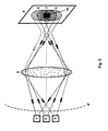
- Bloomed images 6 and 7 of source apertures 1 and 2 are superimposed one over another on the aperture 10 of the second terminal antenna, and thus the optical radiation from each source comes, at least partly, into the second terminal antenna aperture.
- the bloomed image 8 of the photodetector aperture is overlapping with 6 and 7, and thus the radiation from the aperture 10, placed in the area of overlap of 6, 7, and 8, comes to the aperture 3 of the first terminal photodetector.
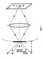
- the shaping of a required point spread function formed by the first terminal antenna is obtained also by placing the transparent plate 11 with non-uniform optical thickness between the antenna lens and the apertures of the sources and photodetectors (see Figure 3).
- the above mentioned plate serves as an extended light source having transverse dimensions equal to the cross-section diameter of the light cone coming from each source aperture at the plate surface.
- the extended light source can provide partial compensation of optical aberrations in the light propagation path from the first terminal antenna to the second terminal antenna.
- Placing of a plate with non-uniform optical thickness in the area optically conjugated with the second terminal relative to the antenna lens provides optimum concentration of radiation in the remote terminal plane 9 and partial compensation of the effect of aberrations in the propagation path on the light distribution in this plane, as thereby an image is built in this plane of the plate 11 part irradiated by radiation coming from the apertures of the sources.
- the plate has thereby a sufficient angular width G of the light scattering pattern to meet the condition G+q n /F > 2NA T ⁇ L n /F, where: F is the antenna lens focal length; NA T is the first terminal antenna numerical aperture; q n is the transverse dimension of the n-th radiation source aperture; and L n is the distance from the n-th source aperture to the plate, then the spherical component of the wavefront of radiation passed through the plate, caused by displacement of source apertures relative to the plate, does not impair the compensation of optical aberrations in the light propagation path from the first terminal antenna.
- NA n is the n-th radiation source numerical aperture
- D n is the source output beam diameter at the plate
- d is the maximum distance between the apertures of sources in the direction transverse to the light propagation direction, provides overlapping of images of plate areas irradiated by the sources.
- the aperture 10 of the second terminal antenna disposed in the area of images overlapping of the plate irradiated areas, will be optically coupled to all sources without any exclusion.
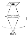
- one of points is shown from where the second terminal transmit radiation goes out, which is intercepted by the lens 5 of the first terminal antenna.
- the radiation is focused at the surface 4' optically conjugated with the second terminal plane 9 relative to the lens 5.
- the radiation propagates with a beamwidth defined by combination of the spherical component equal to 2NA T , and the component G caused by the optically nonuniform plate 11. If the total angular width 2NA T +G, multiplied by the distance H from the plate to the receive photodetector apertures, does exceed the transverse dimensions of the area where the photodetectors and sources apertures are disposed, then the photodetectors will be optically coupled to the aperture 10.
- NA n +G/2 ⁇ NA T the output radiation of sources, after passing through the plate 11, will be within the lens 5 numerical aperture, thus reducing the radiation loss when it passes through this lens.
- Implementation of the first terminal antenna as a focusing lens 5 and an optical fiber piece 12 placed between the lens 5 and the apertures of sources and photodetectors 1, 2, and 3 provides the following:
- the optical fiber piece length S should thereby meet the condition S > Qn 1 /NA, where: Q is the fiber core diameter; NA is its numerical aperture; and n 1 is the fiber material index of refraction.
- the total area where the image of the fiber end is built by the antenna lens and where the second terminal antenna aperture is disposed is optically coupled with any radiation source and any photodetector.
- the optical fiber light-conducting core transverse dimension is selected to be more or equal to the transverse dimension of the area through which the axes are passing of the first terminal radiation source directivity patterns and of the photodetector fields of view in the plane of the optical fiber piece optically coupled with the apertures of radiation sources and photodetectors.
- the angular deflections of radiation source directivity pattern axes and photodetector field of view axes from the optical fiber piece axis at the fiber end optically coupled with the apertures of sources and photodetectors should not exceed the numerical aperture of this optical fiber piece.
- Placing the optical fiber piece end in the area optically conjugated with the second terminal antenna aperture relative to the first terminal antenna lens provides optical coupling, with minimum loss, between all radiation sources and photodetectors and the area where the optical fiber piece end image is built in the second terminal plane. Besides this, in this case optimum compensation of aberrations in the propagation path is achieved due to extension of the light source, which in this case is the optical fiber piece end optically coupled with the antenna lens.
- the thickening as a transparent plate with flat surfaces, attached to the optical fiber end via an immersion layer, where the light-accepting diameter T of the plate is more than 2NA ⁇ h/n 2 (where NA is the optical fiber piece numerical aperture, h is the plate thickness, and n 2 is the plate material index of refraction) provides absence of return glints at the joint of optical fiber cross-section and the thickening (due to the immersion), as well as absence of transmit radiation loss caused by aperture limiting by the side surfaces of the plate (due to the fact that its light-accepting diameter exceeds the transverse dimension of the divergent radiation beam).
- NA the optical fiber piece numerical aperture
- h the plate thickness
- n 2 is the plate material index of refraction
- the antenna as a lens and an optical fiber piece, with the apertures of radiation sources and photodetectors implemented as optical fiber ends while the other ends of fibers are optically coupled, correspondingly, with the sources of optical radiation carrying the transmitted information and with the devices converting the optical carrier radiation into electrical signals, allows to provide high efficiency of optical coupling of the optical fiber piece to apertures of multiple sources and multiple photodetectors without using of complicated and expensive optical lens systems.
- the antenna as a lens and an optical fiber piece, with the light-conducting core cross-section diameter equal to 3p, and attaching to that core the output aperture of radiation source and the receive aperture of the photodetector, allows to provide maximum compactness of the device.
- the radiation source aperture is implemented as an optical fiber end having a cross-section dimension of p, with the other end of the fiber optically coupled with the source of information-carrying optical radiation
- the photodetector aperture is implemented as ends of six optical fibers, each of them having cross-section dimensions of p, with their other ends optically coupled with a device converting the information-carrying optical radiation into electrical signals.
- the loss of receive radiation is small, as the total cross-section area of six optical fiber ends delivering the radiation from the antenna to the photodetector is around 2/3 of the optical fiber piece end cross-section area.
- the loss of receive radiation is thereby only 33% which is acceptable for practical applications.
- the antenna may be implemented as a lens and an optical fiber piece having the cross-section dimension of the light-conducting core equal to 3p, with the transmit apertures of two light sources and the receive aperture of a photodetector attached to it, while the apertures of light sources are implemented as optical fibers having cross-section dimensions of p, with the other ends of fibers optically coupled with the sources of information-carrying optical radiation, and the photodetector receive aperture is implemented as ends of five optical fibers each of them having a cross-section dimension of p, with their other ends optically coupled with a device converting the information-carrying radiation into electrical signals.
- the receive radiation loss is about 45% which is also acceptable for applications.
- this simple and inexpensive design provides optical coupling of two separate light sources and a photodetector with a single transmit/receive antenna without additional lenses and other optical components, while if the proposed solution is not used, the optical system needed for matching of more then one light source with the antenna will be far more complicated.
- implementation versions are shown of the antenna and optical fibers coupling it with the photodetectors and radiation sources (in the cross-sections of optical fiber beams, the point indicates the direction of light from the sources, while the sign + indicates the direction to the photodetectors).
- the antenna consists thereby of a lens 5 and an optical fiber piece 12 to which a bundle of optical fibers 13 is attached consisting of optical fibers delivering the radiation from the sources to the antenna (in the example shown in the left part, there is one such optical fiber, while in the example shown in the right part are two such optical fibers), and of optical fibers delivering the radiation from the antenna to the photodetectors (in the example shown in the left part, there are six such optical fibers, while in the example shown in the right part are five such optical fibers).
- Positions of photodetectors and radiation sources at a in Figure 6 and also at b in Figure 6 may be swapped if necessary, so that any photodetector may be replaced with a radiation source and the source installed where the photodetector was initially positioned.
- the first terminal radiation sources might operate at equal wavelengths as well as at different ones.
- a single photodetector may be used in the second terminal. If different wavelengths are used in various sources of the first terminal, it is expedient to equip the second terminal with multiple photodetectors, with every one of them sensitive to one wavelength only. This makes it possible to implement a free-space optical communication system with wavelength division multiplexing (WDM) of channels.
- WDM wavelength division multiplexing
- the first terminal antenna focusing lens may be implemented as one or more refraction-type or reflection-type optical elements or as a combination thereof.
- "small-aperture" lenses (less than about 50 mm) it may be preferable to make them of refraction type optical components transparent to optical radiation transmitted and received through such lens.
- For larger scale lenses it may be recommended using a concave main reflector, convex secondary reflector and one or more refraction-type elements matching the lens' and photodetectors' and light sources' numerical apertures.
- Implementation of the first terminal antenna lens with means providing its transparency only within spectrum parts occupied by frequency spectra of transmit and receive radiation provides filtering out background radiation such as sunlight and protection of the system components installed behind the lens from damaging by the sunlight. Additional decrease of the background radiation and also of WDM channels cross-talk is achieved by providing the photodetectors with filters blocking optical radiation with optical spectra different from intended for a particular photodetector.
- the above means providing transparency only within spectrum parts occupied by frequency spectra of transmit and receive radiation may be implemented as one or several optical filters installed before or behind the antenna lens, or even inside it, if the lens is implemented as several refraction- and/or refraction-type optical components placed in succession along the optical ray path.
- the expediency of placing the filter (filters) here or there will be determined by the antenna design features. For example, if a refractor-type lens will be used in the antenna, it will be most expedient to install the filter before the lens. If the filter is installed behind the focusing lens, the focused solar radiation may have a power density high enough to damage the filter.
- the above means may be implemented as a corresponding coating which may be deposited onto one or several optical components of the focusing lens.
- One specifically efficient implementation of such means is concave and/or convex mirrors with multi-layer interference coating having reflectivity limited to frequency spectra of the transmit and receive radiation.
- the receive and transmit radiation frequency spectra are close to each other, it may be a single transparency region common for both of them. This is how Sunflower Technologies, where the authors of this application are both working, implemented the transmit/receive reflection-type focusing lens for the system using two wavelengths, 785 nm and 830 nm, for transmission and receiving of optical signals. However, if the spectra are far enough from each other, only beams corresponding to different spectrum parts (transmit and receive, separately) of the total natural illumination spectrum shall be passed through the antenna.
- the free-space optical communication system comprises at least two transmit/receive terminals, each of them comprising one or more radiation sources (designated in the drawings as 1 and/or 2), the apertures of which may be implemented either as radiating areas of photodetectors or as faces of active elements of lasers (semiconductor, gaseous, etc.), or as end faces of optical fibers, while their other ends are optically coupled with radiating areas of light-emitting diodes or active elements of lasers, or to output apertures of other optical devices creating light waves modulated by information signals.
- the terminal comprises also one or more photodetectors 3 which may be selected from known ones. In particular cases, their apertures may be input apertures of devices providing transportation of received optical radiation to converters of this radiation into electrical signals.
- the indicated apertures of radiation sources and photodetectors are disposed with a displacement along their optical axes relative to the surface 4' optically conjugated with the plane 9 of the second terminal antenna aperture 10 relative to the lens 5 of the first terminal antenna.
- the indicated apertures of radiation sources and photodetectors are projected by the first terminal antenna lens as areas 6, 7, and 8 of the plane 9 wherein the second terminal antenna aperture is disposed.
- a single- or multiple-component lens or any other optical focusing system may be used (e.g. a reflector-type or refractor-type telescope).
- the bloomed images 6, 7, and 8 of the indicated apertures are partly overlapping each other, and within the overlapping area the second terminal antenna aperture 10 is disposed (consisting of many points 10'); the second terminal may be similar in its design to the first terminal, or may have a different design (e.g. selected from known ones).
- a plate 11 may be installed having non-uniform optical thickness, e.g. a glass plate with a rough surface. An optimum solution seems to be installation of this plate in the area 4' conjugated with the second terminal antenna aperture 10 relative to the first terminal antenna lens.
- an optical fiber piece 12 may be used with its minimum length selected to provide mixing of the radiation entering it by reflection from its side surfaces. It should be noted that the fiber piece length might considerably exceed the minimum value if this is convenient for the terminal design.
- the optical fiber piece may have an arbitrary cross-section shape (circular, square, oval, etc.).
- the optical fiber end face coupled with the first terminal antenna lens with antireflection coating implemented in any known way, as well as with a thickening, e.g. implemented as a transparent plate having flat surfaces which is attached to the above fiber end via an immersion layer (e.g. a layer of Canadian balsam or glycerin).
- a thickening e.g. implemented as a transparent plate having flat surfaces which is attached to the above fiber end via an immersion layer (e.g. a layer of Canadian balsam or glycerin).
- the apertures of photodetectors and radiation sources may be implemented as a bundle of optical fibers 13, with the number of optical fibers in the bundle selected in accordance with the goals set.
- the number as well as shapes and dimensions of fibers optically coupled with sources of information-carrying optical radiation and, correspondingly, with devices converting the information-carrying optical radiation into electrical signals may be various.
- the number of fibers is seven, all of them have circular cross-sections with a diameter three times less than the diameter of the optical fiber piece which is part of the antenna.
- the seven optical fibers fall into a circle having a three times larger diameter than the fiber diameters; this allows reducing the radiation loss at the joint between these fibers and the optical fiber piece.
- One of these fibers see Figure 6, a) or two of them (see Figure 6, b) serve as a radiation source aperture, while the remaining fibers are optically coupled with a device (or devices) converting the optical radiation into electrical signals.
- the system shown in Figure 2 operates in the following way.
- the information-signal modulated radiation from source apertures 1 and 2 passes through the lens 5 and, by virtue of their proper relative positions, is projected as spots 6 and 7 in the plane 9 of the second terminal antenna aperture 10. Thereafter, the radiation part falling into the aperture 10 is transported to the second terminal photodetector where it is converted into electrical signals.
- the radiation from the second terminal is captured by the first terminal antenna lens 5 and transported to the aperture (apertures) 3 of a photodetector (photodetectors).
- the device shown in Figure 3 operates in the following way.
- the information-signal modulated optical beams from source apertures 1 and 2 are passing through the plate 11 with non-uniform optical thickness; as a result, the beam wavefronts are distorted and their angular spectra are broadened. Thereafter, the beams are passing the lens 5 and are projected as partly overlapping spots 6 and 7 in the plane 9.
- the light intensity distributions in the spots is more uniform than in the previous case shown in Figure 2, if the plate scattering pattern angular width is wide enough to compensate effects of spherical component of the radiation wavefront on averaging large-scale intensity distribution in the second terminal plane.
- the intensity non-uniformities caused by aberrations in the path from the first terminal antenna lens to the second terminal antenna aperture are averaged over the cross-section in the second terminal antenna aperture plane due to broadening of the radiation angular spectrum by the plate.
- the ray path from the second terminal antenna to the first one is shown in Figure 4, where, for example, a point 10' is shown from where the second terminal transmit radiation goes out, which is captured by the first terminal antenna lens 5.
- This radiation is focused at the surface 4', which is optically conjugated with the plane 9 of the second terminal relative to the lens 5.
- the radiation propagates with a divergence defined by combination of a spherical component equal to 2NA T , and a component G caused by the non-uniform plate 11.
- the area 12' diameter should be 2 meters at a distance of 200 m from the first terminal antenna lens, and the focal length of this lens is 100 mm, then an optical fiber piece with a core diameter of 1 mm will be needed.
- using of the plate 11 and of radiation sources having numerical apertures of 0.22 and disposed at a distance of 2.5 mm from the plate will allow to obtain an irradiated area on the plate with a transverse dimension of 1 mm, which is the required result for the case.
Landscapes
- Physics & Mathematics (AREA)
- Electromagnetism (AREA)
- Engineering & Computer Science (AREA)
- Computer Networks & Wireless Communication (AREA)
- Signal Processing (AREA)
- Optical Couplings Of Light Guides (AREA)
- Optical Communication System (AREA)
Applications Claiming Priority (2)
| Application Number | Priority Date | Filing Date | Title |
|---|---|---|---|
| RU2003116577 | 2003-06-04 | ||
| RU2003116577/09A RU2264691C2 (ru) | 2003-06-04 | 2003-06-04 | Система открытой оптической связи |
Publications (3)
| Publication Number | Publication Date |
|---|---|
| EP1484852A2 true EP1484852A2 (de) | 2004-12-08 |
| EP1484852A3 EP1484852A3 (de) | 2005-04-13 |
| EP1484852B1 EP1484852B1 (de) | 2006-09-27 |
Family
ID=33157476
Family Applications (1)
| Application Number | Title | Priority Date | Filing Date |
|---|---|---|---|
| EP04253116A Expired - Lifetime EP1484852B1 (de) | 2003-06-04 | 2004-05-27 | Optisches Freiraum-Kommunikationssystem |
Country Status (4)
| Country | Link |
|---|---|
| EP (1) | EP1484852B1 (de) |
| AT (1) | ATE341132T1 (de) |
| DE (1) | DE602004002515T2 (de) |
| RU (1) | RU2264691C2 (de) |
Cited By (2)
| Publication number | Priority date | Publication date | Assignee | Title |
|---|---|---|---|---|
| US10277316B1 (en) | 2017-05-01 | 2019-04-30 | The United States Of America As Represented By The Secretary Of The Air Force | Free space optical headset |
| CN110441311A (zh) * | 2019-07-22 | 2019-11-12 | 中国科学院上海光学精密机械研究所 | 用于多物面成像的多轴多焦镜头 |
Family Cites Families (7)
| Publication number | Priority date | Publication date | Assignee | Title |
|---|---|---|---|---|
| US4960315A (en) * | 1989-05-19 | 1990-10-02 | At&T Bell Laboratories | Atmosphric optical communication link |
| US5777768A (en) * | 1995-09-01 | 1998-07-07 | Astroterra Corporation | Multiple transmitter laser link |
| CN1350653A (zh) * | 1998-09-16 | 2002-05-22 | 约尔特有限公司 | 无电子线路的无线光纤通信 |
| EP1162770A3 (de) * | 2000-06-08 | 2005-03-09 | Sunflower Technologies, Ltd. | Optische Übertragungsanordnung im freien Raum |
| US6522437B2 (en) * | 2001-02-15 | 2003-02-18 | Harris Corporation | Agile multi-beam free-space optical communication apparatus |
| US6735356B2 (en) * | 2001-05-07 | 2004-05-11 | At&T Corp. | Free space duplexed optical communication with transmitter end multiplexing and receiver and amplification |
| RU28576U1 (ru) * | 2002-04-18 | 2003-03-27 | Общество с ограниченной ответственностью "Подсолнечник Технологии" | Система открытой оптической связи |
-
2003
- 2003-06-04 RU RU2003116577/09A patent/RU2264691C2/ru not_active IP Right Cessation
-
2004
- 2004-05-27 EP EP04253116A patent/EP1484852B1/de not_active Expired - Lifetime
- 2004-05-27 DE DE602004002515T patent/DE602004002515T2/de not_active Expired - Lifetime
- 2004-05-27 AT AT04253116T patent/ATE341132T1/de not_active IP Right Cessation
Cited By (3)
| Publication number | Priority date | Publication date | Assignee | Title |
|---|---|---|---|---|
| US10277316B1 (en) | 2017-05-01 | 2019-04-30 | The United States Of America As Represented By The Secretary Of The Air Force | Free space optical headset |
| CN110441311A (zh) * | 2019-07-22 | 2019-11-12 | 中国科学院上海光学精密机械研究所 | 用于多物面成像的多轴多焦镜头 |
| CN110441311B (zh) * | 2019-07-22 | 2021-10-08 | 中国科学院上海光学精密机械研究所 | 用于多物面成像的多轴多焦镜头 |
Also Published As
| Publication number | Publication date |
|---|---|
| ATE341132T1 (de) | 2006-10-15 |
| EP1484852B1 (de) | 2006-09-27 |
| EP1484852A3 (de) | 2005-04-13 |
| DE602004002515T2 (de) | 2007-06-21 |
| RU2264691C2 (ru) | 2005-11-20 |
| DE602004002515D1 (de) | 2006-11-09 |
Similar Documents
| Publication | Publication Date | Title |
|---|---|---|
| EP0613263B1 (de) | Optisches Netzwerk mit kompaktem Wellenlängendemultiplexer | |
| CN101995610B (zh) | 超轻薄宽光谱全息天线 | |
| AU695818B2 (en) | Low cost optical fibre RF signal distribution system | |
| US6829439B1 (en) | Optical communication device | |
| RU2212763C2 (ru) | Система открытой оптической связи | |
| US9164247B2 (en) | Apparatuses for reducing the sensitivity of an optical signal to polarization and methods of making and using the same | |
| CA1154829A (en) | Modular fibre-optic bus system | |
| JP4449060B2 (ja) | 光ファイバにおける色分散の補償装置及び方法 | |
| KR20010079835A (ko) | 전자장치가 없는 무선 광학통신 | |
| US6965713B2 (en) | Optical beam generating and shaping device | |
| CN115407434A (zh) | 光次组件模组中使用的抛物面透镜装置 | |
| US6381052B1 (en) | Multiplexors with a flat top spectral channel shape | |
| CN210605101U (zh) | 一种基于光波导的多路波分解复用光接收组件 | |
| CN101984565B (zh) | 多通道双功能波分复用光电集成模块 | |
| US9225428B1 (en) | Method and system for alignment of photodetector array to optical demultiplexer outputs | |
| US6832859B1 (en) | Free space optical system with multiple function detectors | |
| CN115499064B (zh) | 基于可变光轴的小型化多芯收发激光通信装置及设计方法 | |
| CN201708807U (zh) | 多通道双功能波分复用光电集成模块 | |
| EP1484852B1 (de) | Optisches Freiraum-Kommunikationssystem | |
| Koonen et al. | Indoor ultra-high capacity optical wireless communication using steerable infrared beams | |
| EP1416307A1 (de) | Bidirektionales Teleskop | |
| US12615461B2 (en) | Integrated optical transceiver apparatus and optical line terminal | |
| LV14146B (lv) | Optiskā sistēma gaisa optisko sakaru ierīcei | |
| NL8304463A (nl) | Optische koppelinrichting met draaiende koppeling. | |
| CN111965760B (zh) | 一种利用折射器件的低损耗oam复用解复用方法及系统 |
Legal Events
| Date | Code | Title | Description |
|---|---|---|---|
| PUAI | Public reference made under article 153(3) epc to a published international application that has entered the european phase |
Free format text: ORIGINAL CODE: 0009012 |
|
| AK | Designated contracting states |
Kind code of ref document: A2 Designated state(s): AT BE BG CH CY CZ DE DK EE ES FI FR GB GR HU IE IT LI LU MC NL PL PT RO SE SI SK TR |
|
| AX | Request for extension of the european patent |
Extension state: AL HR LT LV MK |
|
| PUAL | Search report despatched |
Free format text: ORIGINAL CODE: 0009013 |
|
| AK | Designated contracting states |
Kind code of ref document: A3 Designated state(s): AT BE BG CH CY CZ DE DK EE ES FI FR GB GR HU IE IT LI LU MC NL PL PT RO SE SI SK TR |
|
| AX | Request for extension of the european patent |
Extension state: AL HR LT LV MK |
|
| 17P | Request for examination filed |
Effective date: 20050527 |
|
| AKX | Designation fees paid |
Designated state(s): AT BE BG CH CY CZ DE DK EE ES FI FR GB GR HU IE IT LI LU MC NL PL PT RO SE SI SK TR |
|
| GRAP | Despatch of communication of intention to grant a patent |
Free format text: ORIGINAL CODE: EPIDOSNIGR1 |
|
| GRAS | Grant fee paid |
Free format text: ORIGINAL CODE: EPIDOSNIGR3 |
|
| GRAA | (expected) grant |
Free format text: ORIGINAL CODE: 0009210 |
|
| AK | Designated contracting states |
Kind code of ref document: B1 Designated state(s): AT BE BG CH CY CZ DE DK EE ES FI FR GB GR HU IE IT LI LU MC NL PL PT RO SE SI SK TR |
|
| PG25 | Lapsed in a contracting state [announced via postgrant information from national office to epo] |
Ref country code: IT Free format text: LAPSE BECAUSE OF FAILURE TO SUBMIT A TRANSLATION OF THE DESCRIPTION OR TO PAY THE FEE WITHIN THE PRESCRIBED TIME-LIMIT;WARNING: LAPSES OF ITALIAN PATENTS WITH EFFECTIVE DATE BEFORE 2007 MAY HAVE OCCURRED AT ANY TIME BEFORE 2007. THE CORRECT EFFECTIVE DATE MAY BE DIFFERENT FROM THE ONE RECORDED. Effective date: 20060927 Ref country code: SI Free format text: LAPSE BECAUSE OF FAILURE TO SUBMIT A TRANSLATION OF THE DESCRIPTION OR TO PAY THE FEE WITHIN THE PRESCRIBED TIME-LIMIT Effective date: 20060927 Ref country code: CH Free format text: LAPSE BECAUSE OF FAILURE TO SUBMIT A TRANSLATION OF THE DESCRIPTION OR TO PAY THE FEE WITHIN THE PRESCRIBED TIME-LIMIT Effective date: 20060927 Ref country code: CZ Free format text: LAPSE BECAUSE OF FAILURE TO SUBMIT A TRANSLATION OF THE DESCRIPTION OR TO PAY THE FEE WITHIN THE PRESCRIBED TIME-LIMIT Effective date: 20060927 Ref country code: FI Free format text: LAPSE BECAUSE OF FAILURE TO SUBMIT A TRANSLATION OF THE DESCRIPTION OR TO PAY THE FEE WITHIN THE PRESCRIBED TIME-LIMIT Effective date: 20060927 Ref country code: SK Free format text: LAPSE BECAUSE OF FAILURE TO SUBMIT A TRANSLATION OF THE DESCRIPTION OR TO PAY THE FEE WITHIN THE PRESCRIBED TIME-LIMIT Effective date: 20060927 Ref country code: AT Free format text: LAPSE BECAUSE OF FAILURE TO SUBMIT A TRANSLATION OF THE DESCRIPTION OR TO PAY THE FEE WITHIN THE PRESCRIBED TIME-LIMIT Effective date: 20060927 Ref country code: BE Free format text: LAPSE BECAUSE OF FAILURE TO SUBMIT A TRANSLATION OF THE DESCRIPTION OR TO PAY THE FEE WITHIN THE PRESCRIBED TIME-LIMIT Effective date: 20060927 Ref country code: PL Free format text: LAPSE BECAUSE OF FAILURE TO SUBMIT A TRANSLATION OF THE DESCRIPTION OR TO PAY THE FEE WITHIN THE PRESCRIBED TIME-LIMIT Effective date: 20060927 Ref country code: LI Free format text: LAPSE BECAUSE OF FAILURE TO SUBMIT A TRANSLATION OF THE DESCRIPTION OR TO PAY THE FEE WITHIN THE PRESCRIBED TIME-LIMIT Effective date: 20060927 Ref country code: NL Free format text: LAPSE BECAUSE OF FAILURE TO SUBMIT A TRANSLATION OF THE DESCRIPTION OR TO PAY THE FEE WITHIN THE PRESCRIBED TIME-LIMIT Effective date: 20060927 Ref country code: RO Free format text: LAPSE BECAUSE OF FAILURE TO SUBMIT A TRANSLATION OF THE DESCRIPTION OR TO PAY THE FEE WITHIN THE PRESCRIBED TIME-LIMIT Effective date: 20060927 |
|
| REG | Reference to a national code |
Ref country code: GB Ref legal event code: FG4D |
|
| REG | Reference to a national code |
Ref country code: CH Ref legal event code: EP |
|
| REG | Reference to a national code |
Ref country code: IE Ref legal event code: FG4D |
|
| REF | Corresponds to: |
Ref document number: 602004002515 Country of ref document: DE Date of ref document: 20061109 Kind code of ref document: P |
|
| PG25 | Lapsed in a contracting state [announced via postgrant information from national office to epo] |
Ref country code: DK Free format text: LAPSE BECAUSE OF FAILURE TO SUBMIT A TRANSLATION OF THE DESCRIPTION OR TO PAY THE FEE WITHIN THE PRESCRIBED TIME-LIMIT Effective date: 20061227 Ref country code: BG Free format text: LAPSE BECAUSE OF FAILURE TO SUBMIT A TRANSLATION OF THE DESCRIPTION OR TO PAY THE FEE WITHIN THE PRESCRIBED TIME-LIMIT Effective date: 20061227 Ref country code: SE Free format text: LAPSE BECAUSE OF FAILURE TO SUBMIT A TRANSLATION OF THE DESCRIPTION OR TO PAY THE FEE WITHIN THE PRESCRIBED TIME-LIMIT Effective date: 20061227 |
|
| PG25 | Lapsed in a contracting state [announced via postgrant information from national office to epo] |
Ref country code: ES Free format text: LAPSE BECAUSE OF FAILURE TO SUBMIT A TRANSLATION OF THE DESCRIPTION OR TO PAY THE FEE WITHIN THE PRESCRIBED TIME-LIMIT Effective date: 20070107 |
|
| NLV1 | Nl: lapsed or annulled due to failure to fulfill the requirements of art. 29p and 29m of the patents act | ||
| PG25 | Lapsed in a contracting state [announced via postgrant information from national office to epo] |
Ref country code: PT Free format text: LAPSE BECAUSE OF FAILURE TO SUBMIT A TRANSLATION OF THE DESCRIPTION OR TO PAY THE FEE WITHIN THE PRESCRIBED TIME-LIMIT Effective date: 20070313 |
|
| REG | Reference to a national code |
Ref country code: CH Ref legal event code: PL |
|
| EN | Fr: translation not filed | ||
| PLBE | No opposition filed within time limit |
Free format text: ORIGINAL CODE: 0009261 |
|
| STAA | Information on the status of an ep patent application or granted ep patent |
Free format text: STATUS: NO OPPOSITION FILED WITHIN TIME LIMIT |
|
| 26N | No opposition filed |
Effective date: 20070628 |
|
| PG25 | Lapsed in a contracting state [announced via postgrant information from national office to epo] |
Ref country code: MC Free format text: LAPSE BECAUSE OF NON-PAYMENT OF DUE FEES Effective date: 20070531 |
|
| PG25 | Lapsed in a contracting state [announced via postgrant information from national office to epo] |
Ref country code: FR Free format text: LAPSE BECAUSE OF FAILURE TO SUBMIT A TRANSLATION OF THE DESCRIPTION OR TO PAY THE FEE WITHIN THE PRESCRIBED TIME-LIMIT Effective date: 20070525 Ref country code: GR Free format text: LAPSE BECAUSE OF FAILURE TO SUBMIT A TRANSLATION OF THE DESCRIPTION OR TO PAY THE FEE WITHIN THE PRESCRIBED TIME-LIMIT Effective date: 20061228 |
|
| PG25 | Lapsed in a contracting state [announced via postgrant information from national office to epo] |
Ref country code: IE Free format text: LAPSE BECAUSE OF NON-PAYMENT OF DUE FEES Effective date: 20070528 |
|
| PG25 | Lapsed in a contracting state [announced via postgrant information from national office to epo] |
Ref country code: EE Free format text: LAPSE BECAUSE OF FAILURE TO SUBMIT A TRANSLATION OF THE DESCRIPTION OR TO PAY THE FEE WITHIN THE PRESCRIBED TIME-LIMIT Effective date: 20060927 |
|
| PG25 | Lapsed in a contracting state [announced via postgrant information from national office to epo] |
Ref country code: FR Free format text: LAPSE BECAUSE OF FAILURE TO SUBMIT A TRANSLATION OF THE DESCRIPTION OR TO PAY THE FEE WITHIN THE PRESCRIBED TIME-LIMIT Effective date: 20060927 |
|
| PG25 | Lapsed in a contracting state [announced via postgrant information from national office to epo] |
Ref country code: LU Free format text: LAPSE BECAUSE OF NON-PAYMENT OF DUE FEES Effective date: 20070527 Ref country code: CY Free format text: LAPSE BECAUSE OF FAILURE TO SUBMIT A TRANSLATION OF THE DESCRIPTION OR TO PAY THE FEE WITHIN THE PRESCRIBED TIME-LIMIT Effective date: 20060927 |
|
| PG25 | Lapsed in a contracting state [announced via postgrant information from national office to epo] |
Ref country code: HU Free format text: LAPSE BECAUSE OF FAILURE TO SUBMIT A TRANSLATION OF THE DESCRIPTION OR TO PAY THE FEE WITHIN THE PRESCRIBED TIME-LIMIT Effective date: 20070328 |
|
| REG | Reference to a national code |
Ref country code: GB Ref legal event code: 732E Free format text: REGISTERED BETWEEN 20100916 AND 20100922 |
|
| PGFP | Annual fee paid to national office [announced via postgrant information from national office to epo] |
Ref country code: TR Payment date: 20101125 Year of fee payment: 7 |
|
| PGFP | Annual fee paid to national office [announced via postgrant information from national office to epo] |
Ref country code: DE Payment date: 20130530 Year of fee payment: 10 Ref country code: GB Payment date: 20130528 Year of fee payment: 10 |
|
| PG25 | Lapsed in a contracting state [announced via postgrant information from national office to epo] |
Ref country code: TR Free format text: LAPSE BECAUSE OF NON-PAYMENT OF DUE FEES Effective date: 20110527 |
|
| REG | Reference to a national code |
Ref country code: DE Ref legal event code: R119 Ref document number: 602004002515 Country of ref document: DE |
|
| GBPC | Gb: european patent ceased through non-payment of renewal fee |
Effective date: 20140527 |
|
| REG | Reference to a national code |
Ref country code: DE Ref legal event code: R079 Ref document number: 602004002515 Country of ref document: DE Free format text: PREVIOUS MAIN CLASS: H04B0010100000 Ipc: H04B0010110000 |
|
| REG | Reference to a national code |
Ref country code: DE Ref legal event code: R119 Ref document number: 602004002515 Country of ref document: DE Effective date: 20141202 Ref country code: DE Ref legal event code: R079 Ref document number: 602004002515 Country of ref document: DE Free format text: PREVIOUS MAIN CLASS: H04B0010100000 Ipc: H04B0010110000 Effective date: 20150206 |
|
| PG25 | Lapsed in a contracting state [announced via postgrant information from national office to epo] |
Ref country code: DE Free format text: LAPSE BECAUSE OF NON-PAYMENT OF DUE FEES Effective date: 20141202 |
|
| PG25 | Lapsed in a contracting state [announced via postgrant information from national office to epo] |
Ref country code: GB Free format text: LAPSE BECAUSE OF NON-PAYMENT OF DUE FEES Effective date: 20140527 |