EP1484916A2 - Appareil de caméra - Google Patents
Appareil de caméra Download PDFInfo
- Publication number
- EP1484916A2 EP1484916A2 EP04102507A EP04102507A EP1484916A2 EP 1484916 A2 EP1484916 A2 EP 1484916A2 EP 04102507 A EP04102507 A EP 04102507A EP 04102507 A EP04102507 A EP 04102507A EP 1484916 A2 EP1484916 A2 EP 1484916A2
- Authority
- EP
- European Patent Office
- Prior art keywords
- resolution
- unit
- recording medium
- photographing apparatus
- dsc
- Prior art date
- Legal status (The legal status is an assumption and is not a legal conclusion. Google has not performed a legal analysis and makes no representation as to the accuracy of the status listed.)
- Withdrawn
Links
Images


Classifications
-
- H—ELECTRICITY
- H04—ELECTRIC COMMUNICATION TECHNIQUE
- H04N—PICTORIAL COMMUNICATION, e.g. TELEVISION
- H04N1/00—Scanning, transmission or reproduction of documents or the like, e.g. facsimile transmission; Details thereof
- H04N1/21—Intermediate information storage
- H04N1/2104—Intermediate information storage for one or a few pictures
- H04N1/2112—Intermediate information storage for one or a few pictures using still video cameras
- H04N1/212—Motion video recording combined with still video recording
-
- H—ELECTRICITY
- H04—ELECTRIC COMMUNICATION TECHNIQUE
- H04N—PICTORIAL COMMUNICATION, e.g. TELEVISION
- H04N5/00—Details of television systems
- H04N5/76—Television signal recording
- H04N5/765—Interface circuits between an apparatus for recording and another apparatus
- H04N5/77—Interface circuits between an apparatus for recording and another apparatus between a recording apparatus and a television camera
- H04N5/772—Interface circuits between an apparatus for recording and another apparatus between a recording apparatus and a television camera the recording apparatus and the television camera being placed in the same enclosure
-
- H—ELECTRICITY
- H04—ELECTRIC COMMUNICATION TECHNIQUE
- H04N—PICTORIAL COMMUNICATION, e.g. TELEVISION
- H04N2101/00—Still video cameras
-
- H—ELECTRICITY
- H04—ELECTRIC COMMUNICATION TECHNIQUE
- H04N—PICTORIAL COMMUNICATION, e.g. TELEVISION
- H04N2201/00—Indexing scheme relating to scanning, transmission or reproduction of documents or the like, and to details thereof
- H04N2201/21—Intermediate information storage
- H04N2201/212—Selecting different recording or reproducing modes, e.g. high or low resolution, field or frame
-
- H—ELECTRICITY
- H04—ELECTRIC COMMUNICATION TECHNIQUE
- H04N—PICTORIAL COMMUNICATION, e.g. TELEVISION
- H04N2201/00—Indexing scheme relating to scanning, transmission or reproduction of documents or the like, and to details thereof
- H04N2201/21—Intermediate information storage
- H04N2201/216—Arrangements for recording on different types of storage medium, e.g. IC card or magnetic tape; Recording on a plurality of storage media
-
- H—ELECTRICITY
- H04—ELECTRIC COMMUNICATION TECHNIQUE
- H04N—PICTORIAL COMMUNICATION, e.g. TELEVISION
- H04N5/00—Details of television systems
- H04N5/76—Television signal recording
- H04N5/907—Television signal recording using static stores, e.g. storage tubes or semiconductor memories
-
- H—ELECTRICITY
- H04—ELECTRIC COMMUNICATION TECHNIQUE
- H04N—PICTORIAL COMMUNICATION, e.g. TELEVISION
- H04N9/00—Details of colour television systems
- H04N9/79—Processing of colour television signals in connection with recording
- H04N9/7921—Processing of colour television signals in connection with recording for more than one processing mode
-
- H—ELECTRICITY
- H04—ELECTRIC COMMUNICATION TECHNIQUE
- H04N—PICTORIAL COMMUNICATION, e.g. TELEVISION
- H04N9/00—Details of colour television systems
- H04N9/79—Processing of colour television signals in connection with recording
- H04N9/80—Transformation of the television signal for recording, e.g. modulation, frequency changing; Inverse transformation for playback
- H04N9/804—Transformation of the television signal for recording, e.g. modulation, frequency changing; Inverse transformation for playback involving pulse code modulation of the colour picture signal components
- H04N9/8042—Transformation of the television signal for recording, e.g. modulation, frequency changing; Inverse transformation for playback involving pulse code modulation of the colour picture signal components involving data reduction
- H04N9/8047—Transformation of the television signal for recording, e.g. modulation, frequency changing; Inverse transformation for playback involving pulse code modulation of the colour picture signal components involving data reduction using transform coding
Definitions
- the present invention relates to a camera apparatus comprising moving image-capturing means, means for receiving a solid state memory device, a deck for receiving a video cassette and processing means configured to selectively output image data from the moving image-capturing means to the means for receiving a solid state memory device or the deck.
- DSCs digital still cameras
- PC personal computers
- DSCs make editing or correcting images easy.
- DSCs can be connected to external computers to transmit the captured images.
- DSCs are similar in structure to general cameras, so DSCs are convenient to carry.
- a known type of DSC includes a lens device, a memory device, a signal converter and a display.
- DSCs are usually only used for capturing still images.
- DSCs are capable of capturing motion pictures
- motion pictures require extensive storage capacity and, therefore, only a very limited-duration motion picture can be stored on current memory devices. Therefore, DSCs are not effective for capturing motion pictures.
- DSCs since many DSCs do not have any means for recording and reproducing sound, it is somewhat ineffective to use DSCs for recording and reproducing motion pictures.
- DSCs equipped with image and sound recording and reproducing means have been suggested.
- a camcorder records and reproduces images and sounds on a recording medium such as a tape.
- a digital video camera (DVC) is another example of such a device.
- a known type of DVC includes a lens device, a signal converter, a deck device for recording and reproducing captured images and a display.
- Such a DVC usually uses a cassette tape as a recording medium and, therefore, the cassette tape is usually mounted on the deck device to record motion pictures as they are captured.
- DVCs are provided with microphones and speaker devices and are capable of recording with the cassette tape for more than 1 hour.
- DVCs can also photograph still images.
- DVCs are mainly used for capturing motion pictures.
- DVCs have more complex functions and construction than DSCs, DVCs are usually larger in size and more expensive than DSCs.
- a customer in order to photograph motion pictures as well as still images, a customer usually purchases both a DSC and a DVC. As a result, the customer suffers the financial burden of having to buy two expensive devices. Furthermore, the customer has to carry both a DSC and a DVC to use them.
- the DUOCAM uses both a memory card and a magnetic tape as recording media for storing images or motion pictures and, accordingly, the user may select either of the two to record the images he or she is photographing.
- Memory cards have the advantage that they are compact-sized and can be directly connected to a PC either using a reader or via a cable connection to the DUOCAM, which enables easy transmission of data.
- memory cards have relatively small memory capacities.
- Magnetic tapes have large memory capacities, but cannot compare to memory cards when it comes to compactness and data transmission efficiency. Therefore, from the point of view of efficient space utilization, it is more efficient to store low resolution images on the memory card, i.e.
- the DUOCAM needs a function to automatically select the resolution of the recorded images in accordance with a recording medium selection made by the user.
- the user has to select the resolution in addition to the recording medium, which is undesirably time consuming.
- a camera apparatus characterised in that the processing means is configured to selectively set the resolution of said image data to a first or a second resolution according to whether said image data is output to the means for receiving a solid state memory device or the deck.
- the first resolution is lower than the second resolution.
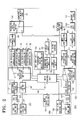
- the camera apparatus (or photographing apparatus) comprises a main body 100, an image-capturing unit (or complex camera unit) 200 connected to the main body 100 and a mode selection switch unit 300.
- the image-capturing unit 200 comprises a digital still camera (DSC) unit 201 and a digital video camera (DVC) unit 202.
- the DSC unit 201 and the DVC unit 202 are for different image types and, therefore, they are driven independently from each other.
- the DSC unit 201 comprises a DSC lens unit 211, a DSC CCD 221 and a DSC lens driving unit 231, and the DVC unit 202 comprises a DVC lens unit 212, a DVC CCD 222 and a DVC lens driving unit 232.
- the DSC lens driving unit 231 drives the DSC lens unit 211 in accordance with control signals from the DSC control unit 142.
- An optical image, which is converged using the DSC lens unit 211, is photoelectrically converted into electric signals at the DSC CCD 221 and the converted signals are transmitted to the DSC signal processing block 111.
- the DSC CCD 221 preferably uses progressive scanning.
- the DVC lens driving unit 232 drives the DVC lens unit 212 in accordance with control signals from the main control unit 141.
- An optical image, which is converged using the DVC lens unit 212, is photoelectrically converted into electric signals at the DVC CCD 222 and the converted signals are transmitted to the DVC signal processing block 112.
- the DVC CCD 222 preferably uses interlace scanning.
- the image-capturing unit 200 is mounted such that, it can be rotated by a user about a Z-axis by more than about 180° with respect to the main body 100.
- One of the DSC unit 201 and the DVC unit 202 of the image-capturing unit 200 performs image-capturing in dependence on the rotation angle of the image-capturing unit 200 with respect to the main body 100. More specifically, whichever camera unit is positioned within the range, which projects in a forward direction between ⁇ 45° with respect to an X-axis performs image-capturing.
- the elements shown as dotted lines represent the DSC lens unit 211, the DSC CCD 221, the DVC lens unit 212 and the DVC CCD 222 respectively, which are installed inside the image-capturing unit 200.
- the DSC lens driving unit 231 and the DVC lens driving unit 232 are omitted from the drawing.
- the DSC is in an operation mode in which the DSC unit 201 performs image-capturing, because the DSC lens unit 211 and the DSC CCD 221 are positioned within the range R, which projects in a forward direction between ⁇ 45 degrees with respect to an X-axis.
- the range R which projects in a forward direction between ⁇ 45 degrees with respect to an X-axis.
- there is no camera unit positioned within the range R which projects in a forward direction between ⁇ 45 degrees with respect to an X-axis. Accordingly, neither camera unit is positioned to perform image-capturing.
- the DVC lens unit 212 and the DVC CCD 222 are positioned within the range R of ⁇ 45° with reference to the left side of the X-axis. Accordingly, the DVC unit 202, which is positioned within the range R of ⁇ 45° with reference to the left side of the X-axis, performs image-capturing.
- the main body 100 of the camera apparatus may house respective components of the camera apparatus, except the components of the image-capturing unit 200 and the mode selection switch unit 300.
- the DSC signal processing block 111 processes signals from the D SC CCD 221 in frame units and outputs digital still image data.
- the DSC signal processing block 111 may modify colour, colour depth, colour brightness and shutter speed settings during image-capturing, in response to control signals from the DSC control unit 142.
- a third resolution converting unit 173 is provided for converting the digital still image data received from the DSC signal processing block 111 to 2272x1704 resolution. Also, a fourth resolution converting unit 174 for converting the digital still image data to 2272x1504 resolution, a fifth resolution converting unit 175 for converting to 1600 ⁇ 1200 resolution and a sixth resolution converting unit 176 to convert to 640 ⁇ 480 resolution are provided.
- a JPEG compression unit 181 compresses the data received from the DSC signal processing block 111 to JPEG formatted data.
- the JPEG formatted data is stored on a removable IC memory card 121.
- the DVC signal processing block 112 processes signals from the DVC CCD 222 in field units and outputs digital motion picture data.
- the DVC signal processing block 112 can modify colour, colour depth, colour brightness and shutter speed settings, in response to control signals from the main control unit 141.
- a first resolution converting unit 171 converts digital motion picture data received from the DVC signal processing block 112 to 320x240 resolution.
- An MPEG compression unit 182 compresses the received data from the first resolution converting unit 171 to MPEG formatted data.
- the MPEG formatted data is stored on a removable IC memory card 121.
- a second resolution converting unit 172 converts digital motion picture data received from the DVC signal processing block 112 to 740x480 resolution.
- a DV compression unit 183 compresses the data received from the second resolution converting unit 172 to DV formatted data and the DV formatted data is stored on the magnetic tape 122 using a VCR deck 124.
- a speaker 13 for outputting reproduced sound and a microphone 132 for acquiring external sound are provided on a part of the main body 100 facing in the image-capturing direction X.
- the IC memory card 121 can directly connect to a PC, which enables easy data transmission. However, having a relatively small memory capacity, the IC memory card 121 is usually used for the storage of a small-volume of data.
- the IC memory card 121 is one type of recording medium, which is usually formed as a card.
- the IC memory card 121 has one or more semiconductor memories contained in the casing and an interface connector provided at an end, which is usually used to expand memory capacity.
- the IC memory card 121 can be categorized depending on the type of the memories contained therein, such as a RAM card, a flash memory card or a non-volatile semiconductor memory card.
- the magnetic tape 122 is inserted in the VCR deck 124, which is driven by the VCR deck driving unit 123, and has a larger memory capacity than the IC memory card 121.
- a character generating unit 155 receives a control signal from the main control unit 141 and accordingly generates certain letters at corresponding positions on the display unit 150.
- An IEEE-1394 interface unit 191 is used to exchange data with other external devices and is usually used for interfacing with a PC.
- the digital image data can be transmitted to the PC via the IEEE-1394 interface unit 191 and the digital image data can also be recorded from the PC to the magnetic tape 122.
- the display unit 150 includes a viewfinder 151, which is provided on the main body 100 for displaying captured images, and an LCD panel 152, which is also provided on the main body 100.
- Still images, captured by the DSC, are stored on the removable IC memory card 121.
- the user is able to select the resolution for the still images being stored using a DSC resolution selecting unit (not shown).
- the data size increases and, thus, the number of photos that can be stored decreases.
- the data size decreases and, therefore, the number of photos that can be stored increases.
- the storage capacity of the removable IC memory card 121 is 32MB and the resolution is 2272x1704, approximately 52 photos can be stored.
- the resolution set at 640x480 approximately 360 photos can be stored.
- the DSC resolution selecting unit may comprise a key input unit 130, a character generating unit 155 and a display unit 150.
- the key input unit 130 is provided with a menu key for inputting a command to display a menu screen on the display unit 150, a direction key for moving a cursor with respect to the items selectively arranged on the menu screen and a selection key for selecting the item where the cursor is placed.
- the key input unit 130 transmits a menu display signal to the main control unit 141.
- the key input unit 130 transmits a cursor moving signal to the main control unit 141 and when the user presses the selection key the key input unit 130 transmits an item selection signal.
- the main control unit 141 Upon receiving the menu display signal, the main control unit 141 controls the character generating unit 155, which displays a menu screen on the display unit 150. Upon receiving a cursor moving signal, the main control unit 141 controls the character generating unit 155 to move the cursor displayed on the display unit 150. Upon receiving the item selection signal, the main control unit 141 controls the character generating unit 155 to show a sub-menu of the item on the display unit and, in the absence of a sub-menu, the main control unit 141 performs the operations corresponding to the menu items.
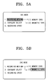
- the DSC menu screen is displayed on the display unit 150. Additionally, when the cursor is placed on the item '1. resolution' and the selection key is pressed, the sub-menu of the item '1. resolution', i.e. '(1) L2272 ⁇ 1704', '(2) P2272 ⁇ 1504', '(3) M1600 ⁇ 1200' and '(4) S640x480' is displayed.
- the motion pictures captured by the DVC are selectively stored on the removable IC memory card 121 or the magnetic tape 122, in accordance with a storage path that is set by the user as he/she likes.
- the recording medium selecting switch 131 outputs a memory recording mode signal or a tape recording mode signal to the main control unit 141 in accordance with the selection made by the user.
- the user may select a recording medium using a recording medium setting unit (not shown), which includes the key input unit 130, the character generating unit 155 and the display unit 150.
- a recording medium setting unit (not shown), which includes the key input unit 130, the character generating unit 155 and the display unit 150.
- the functions of the respective parts are identical to those as described above in the description of the DSC resolution selecting unit.
- the DVC menu screen is displayed on the display unit 150.
- the sub-menus of the '1. recording medium' item such as '(1) memory card' and '(2) magnetic tape', are displayed.
- the main control unit 141 sets a storage path such that captured motion pictures are stored on the magnetic tape 122.
- the main control unit 141 and the DSC control unit 142 constitute a control unit 140.
- the main control unit 141 determines whether the current operation mode is the DSC operation mode or the DVC operation mode based on an operation mode signal received from the mode selection switch unit 300.
- the main control unit 141 controls the DSC control unit 142, which controls the DSC lens driving unit 231 and the DSC signal processing block 111, respectively. Accordingly, an optical image captured using the DSC lens unit 211 is photoelectrically converted into electrical signals at the DSC CCD 221 and the converted signals are converted into digital still image data at the DSC signal processing block 111.
- the main control unit 141 changes the resolution of the output digital still image data based on a signal received from the DSC resolution selecting unit. In other words, the main control unit 141 controls the digital still image data output from the DSC signal processing block 111 to be transmitted to any one of the third to sixth resolution converting units in dependence on the DSC resolution selecting switch 113. Digital still image data transmitted to the third resolution converting unit 173 is converted to 2272x1704 resolution and digital still image data transmitted to the fourth resolution converting unit 174 is converted to 2272x1504 resolution. Digital still image data transmitted to the fifth resolution converting unit 175 is converted to 1600x1200 resolution and digital still image data transmitted to the sixth resolution converting unit 176 is converted to 640x480 resolution.
- the converted data is compressed to JPEG formatted data at the JPEG compression unit 181.
- the main control unit 141 controls the JPEG formatted data from the JPEG compression unit 181 to be stored on the removable IC memory card 121 in dependence on the stored data selecting switch 120.
- the main control unit 141 controls the DVC lens driving unit 232 and the DVC signal processing block 112 so that the optical image converged through the DVC lens unit 212 can be photoelectrically converted to electrical signals at the DVC CCD 222 and converted to digital motion picture data at the DVC signal processing block 112.
- the main control unit 141 determines whether the current recording mode is the memory recording mode or the tape recording mode based on a recording mode signal received from the recording medium switch 131 or from the recording medium setting unit (not shown).
- the main control unit 141 manipulates the DVC resolution selecting switch 114 so that the digital motion picture data output from the DVC signal processing block 112 can be transmitted to the first resolution converting unit 171.
- the first resolution converting unit 171 converts the digital motion picture data to 320x240 resolution.
- the data output from the first resolution converting unit 171 is compressed to MPEG formatted data at the MPEG compressing unit 182.
- the main control unit 141 controls the recording data selecting switch 120 so that the MPEG formatted data can be stored on the removable IC memory card 121.
- the main control unit 141 controls the DVC resolution selecting switch 114 so that the digital motion picture data output from the DVC signal processing block 112 can be transmitted to the second resolution converting unit 172.
- the second resolution converting unit 172 converts the digital motion picture data to 720X480 resolution.
- the data output from the second resolution converting unit 172 is compressed to DV formatted data at the DV compressing unit 183 and stored on the magnetic tape 122 using the VCR deck 124.
- the mode selection switch unit 300 operates in association with the image-capturing unit 200.
- the mode selection switch unit 300 outputs an operation mode signal corresponding to the rotation angle of the image-capturing unit 200 to the main control unit 141 and the main control unit 141 determines the current operation mode using the received operation mode signal.
- the mode selection switch unit 300 outputs a DSC operation mode signal to the main control unit 141 and the control unit 140 operates the DSC unit 201, while keeping the DVC unit 202 off.
- the mode selection switch unit 300 outputs a DVC operation mode signal to the main control unit 141 and, accordingly, the control unit 140 operates the DVC unit 202 while keeping the DSC unit 201 off.
- the mode selection switch unit 300 comprises first and second connection patterns 161, 162 provided on the main body 100 and a connection terminal 230 provided on the image-capturing unit 200 for contacting either one of the two connection patterns 161, 162.
- the main body 100 and the image-capturing unit 200 are rotatably coupled to each other such that the holes h1 and h2 are opposite each other.
- the connection terminal 230 contacts either the first connection pattern 161 or the second connection pattern 162 in accordance with the rotation angle of the image-capturing unit 200 with respect to the main body 100.
- the first connection pattern 161 is connected to a first port of the main control unit 141 and the second connection pattern 162 is connected to a second port of the main control unit 141.
- the DSC unit 201 is selected by the mode selection switch unit 300 when the connection terminal 230 contacts the first connection pattern 161.
- a binary signal of '1' corresponding to a DSC operation mode signal for operating the DSC unit 201 is output to the first port of the main control unit 141.
- a binary signal of '0' is output to the second port of the main control unit 141.
- connection terminal 230 When the connection terminal 230 contacts the second connection pattern 162 after the image-capturing unit 200 has been rotated.
- the connection terminal 230 is within a range that projects in a backward direction between ⁇ 90 degrees with respect to an X-axis.
- a binary signal of '1' corresponding to a DVC operation mode signal is output to the second port of the main control unit 141 and a binary signal of '0' is output to the first port of the main control unit 141.
- the mode selection switch unit 300 comprises third and fourth connection patterns 163, 164 in addition to the first and second connection patterns 161, 162 of the main body 100 and is constructed such that the connection terminal 230 which is provided on the image-capturing unit 200 comes into contact with one of the connection patterns 161, 162, 163, 164.
- the connection terminal 230 contacts one of the first to fourth connection patterns 161, 162, 163, 164 in dependence on the rotation angle of the image-capturing unit 200 with respect to the main body 100.
- the first connection pattern 161 is connected to the first port of the main control unit 141, the second connection pattern 162 to the second port, and the third and fourth connection patterns 163, 164 are not connected to the ports of the main control unit 141.
- connection terminal 230 contacts the third connection pattern 163 when the rotation angle of the image-capturing unit 200 falls within a third range, which projects upwards between ⁇ 45° with respect to a Y-axis. In this position, no operation mode signal is output to the ports of the main control unit 141. The same situation applies to the case where the connection terminal 230 contacts the fourth connection pattern 164. Accordingly, in the absence of an operation mode signal, the control unit 140 turns off the camera unit and, therefore, neither the DSC unit 201 nor the DVC unit 202 is operated.
- the first to fourth connection patterns 161, 162, 163, 164 are arranged at 90° intervals.
- the DSC unit 201 is operated.
- the DVC unit 202 is operated.
- No camera unit is operated when the connection terminal 230 is positioned within a range that projects either in an upward or downward direction between ⁇ 45 degrees with respect to a Y-axis.
- both of the camera units are in an off state when the connection terminal 230 is positioned within a range that projects either in an upward or downward direction between ⁇ 45 degrees with respect to a Y-axis. This is to prevent the undesirable collision of the DSC or DVC lens units 211, 212 with the main body 100 in the case that the user selects a zoom function and rotates the image-capturing unit 200 with the DSC 211 and DVC 212 lens units extended.
- a mode switch unit 310 is provided on a contact surface between the image-capturing unit 200 and the main body 100 and a DSC mode switch 311 and a DVC mode switch 312 are provided on the mode switch unit 310.
- the DSC mode switch 311 is connected to the first port of the main control unit 141 and the DVC mode switch 312 is connected to the second port of the main control unit 141.
- the mode switch unit 310, the DSC mode switch 311 and the DVC mode switch 312 are also rotated altogether.
- the DSC mode switch 311 rotates and switches within the ranges d1 and d2.
- a binary signal of '1' corresponding to a DSC operation mode signal to operate the DSC unit 201 is output to the first port of the main control unit 141.
- a binary signal of '0' is output to the second port of the main control unit 141.
- the DVC mode switch 312 rotates and switches within the ranges d3 and d4.
- a binary signal of '1' of DVC operation mode signal to operate the DVC unit 202 is output to the second port of the main control unit 141 and a binary signal of '0' is output to the first port of the main control unit 141.
- the main control unit 141 determines the operation mode based on the operation mode signal received from the mode selection switch unit 300 (S500).
- the DSC CCD 221 photoelectrically converts the optical image converged through the DSC lens unit 211 into electrical signals.
- the electrical signals are then transmitted to the DSC signal processing block 111 (S511).
- the DSC signal processing block 111 converts the signals to digital still image data (S513).
- the main control unit 141 sets a desired resolution (S5151, S5153, S5155) based on the signals received from the DSC resolution selecting unit.
- the digital still image data which is output from the DSC signal processing block 111, is converted to one resolution from among the resolutions of 2272 ⁇ 1704, 2272x1504, 1600x1200 and 640x480 (S5171, S5173, S5175, S5177).
- the JPEG compressing unit 181 compresses the converted data to JPEG formatted data (S518).
- the JPEG formatted data is stored on the removable IC memory card 121 (S519).
- the DVC CCD 222 photoelectrically converts the optical image converged through the DVC lens unit 212 into electrical signals and transmits the signals to the DVC signal processing block 112 so that the DVC signal processing block 112 can convert the received signals into digital motion picture data (S521, S523).
- the main control unit 141 sets the recording mode (S525) based on a recording mode signal received from the recording medium selecting switch 131 or the recording medium setting unit (not shown).
- the digital motion picture data output from the DVC signal processing block 112 is converted to 320x240 resolution (S5271).
- the converted data is then compressed to MPEG formatted data at the MPEG compressing unit 182 (S5281).
- the MPEG formatted data is stored on the removable IC memory card 121 (S5291).
- the digital motion picture data output from the DVC signal processing block 112 is converted to 720x480 resolution (S5272).
- the converted data is compressed to digital video (DV) formatted data at the DV compressing unit 183 (S5282).
- the DV formatted data is stored on the magnetic tape using the VCR deck 124 (S5292).
- the resolution is automatically selected depending on the user selection of the recording medium. More specifically, because a higher resolution is automatically set for the recording medium with a large memory capacity and a lower resolution is automatically set for the recording medium with a smaller memory capacity, the user does not have to set the resolution every time he/she selects the recording medium to use.
Landscapes
- Engineering & Computer Science (AREA)
- Multimedia (AREA)
- Signal Processing (AREA)
- Studio Devices (AREA)
- Television Signal Processing For Recording (AREA)
Applications Claiming Priority (2)
| Application Number | Priority Date | Filing Date | Title |
|---|---|---|---|
| KR1020030035770A KR20040104236A (ko) | 2003-06-03 | 2003-06-03 | 해상도를 자동으로 설정하는 촬영장치 및 그 방법 |
| KR2003035770 | 2003-06-03 |
Publications (2)
| Publication Number | Publication Date |
|---|---|
| EP1484916A2 true EP1484916A2 (fr) | 2004-12-08 |
| EP1484916A3 EP1484916A3 (fr) | 2008-07-09 |
Family
ID=33157379
Family Applications (1)
| Application Number | Title | Priority Date | Filing Date |
|---|---|---|---|
| EP04102507A Withdrawn EP1484916A3 (fr) | 2003-06-03 | 2004-06-03 | Appareil de caméra |
Country Status (5)
| Country | Link |
|---|---|
| US (1) | US20040246349A1 (fr) |
| EP (1) | EP1484916A3 (fr) |
| JP (1) | JP4028511B2 (fr) |
| KR (1) | KR20040104236A (fr) |
| CN (1) | CN1574909A (fr) |
Cited By (2)
| Publication number | Priority date | Publication date | Assignee | Title |
|---|---|---|---|---|
| EP1924093A1 (fr) * | 2006-11-17 | 2008-05-21 | Samsung Electronics Co., Ltd. | Appareil photographique ayant une fonction de réglage automatique et méthode associée |
| EP2026348A1 (fr) * | 2007-08-09 | 2009-02-18 | Hitachi Ltd. | Appareil d'enregistrement/reproduction et procédé de configuration du mode d'enregistrement pour celui-ci |
Families Citing this family (14)
| Publication number | Priority date | Publication date | Assignee | Title |
|---|---|---|---|---|
| KR20040104237A (ko) * | 2003-06-03 | 2004-12-10 | 삼성전자주식회사 | 압축방식을 자동으로 설정하는 촬영장치 및 방법 |
| US8634458B2 (en) * | 2005-02-23 | 2014-01-21 | Canon Kabushiki Kaisha | Image processing apparatus |
| KR100813978B1 (ko) * | 2006-02-22 | 2008-03-17 | 삼성전자주식회사 | 멀티미디어 데이터를 기록 및 재생하는 방법 및 장치 |
| JP2007325040A (ja) * | 2006-06-01 | 2007-12-13 | Matsushita Electric Ind Co Ltd | 記録装置 |
| JP4788522B2 (ja) * | 2006-08-10 | 2011-10-05 | ソニー株式会社 | データ処理装置及びデータ処理方法、並びにコンピュータ・プログラム |
| JP4745919B2 (ja) * | 2006-08-28 | 2011-08-10 | キヤノン株式会社 | 撮像装置及び撮像装置の制御方法 |
| JP4921075B2 (ja) * | 2006-08-28 | 2012-04-18 | キヤノン株式会社 | 撮像装置及びその制御方法 |
| JP4795297B2 (ja) * | 2007-04-05 | 2011-10-19 | キヤノン株式会社 | 撮像装置及びその制御方法 |
| JP2009044639A (ja) * | 2007-08-10 | 2009-02-26 | Hitachi Ltd | 映像記録装置及び映像記録方法 |
| CN102164231A (zh) * | 2011-01-24 | 2011-08-24 | 南京壹进制信息技术有限公司 | 基于敏感信息的分辨率可动态调节的监控装置及方法 |
| JP6119447B2 (ja) * | 2013-06-19 | 2017-04-26 | 株式会社Jvcケンウッド | 撮像システム、及び制御方法 |
| CN105227848B (zh) * | 2015-10-30 | 2019-04-05 | 宁波萨瑞通讯有限公司 | 一种拍摄格式的切换方法及拍摄装置 |
| JP6583457B2 (ja) * | 2018-03-22 | 2019-10-02 | 株式会社Jvcケンウッド | 撮像装置及び制御方法 |
| JP6583458B2 (ja) * | 2018-03-22 | 2019-10-02 | 株式会社Jvcケンウッド | 撮像装置及び制御方法 |
Family Cites Families (6)
| Publication number | Priority date | Publication date | Assignee | Title |
|---|---|---|---|---|
| JP2904736B2 (ja) * | 1995-12-28 | 1999-06-14 | 三星電子株式会社 | スチルカメラ一体型ビデオカメラ |
| JPH10336705A (ja) * | 1997-06-02 | 1998-12-18 | Canon Inc | 複眼カメラ |
| JP3610195B2 (ja) * | 1997-07-04 | 2005-01-12 | キヤノン株式会社 | 撮像装置 |
| US6151069A (en) * | 1997-11-03 | 2000-11-21 | Intel Corporation | Dual mode digital camera for video and still operation |
| JP4536173B2 (ja) * | 1998-07-22 | 2010-09-01 | ソニー株式会社 | 画像記録装置及び画像記録方法 |
| US7768552B1 (en) * | 1999-07-23 | 2010-08-03 | Hewlett-Packard Development Company, L.P. | Digital still camera with still and motion image capabilities |
-
2003
- 2003-06-03 KR KR1020030035770A patent/KR20040104236A/ko not_active Ceased
-
2004
- 2004-03-30 JP JP2004100191A patent/JP4028511B2/ja not_active Expired - Fee Related
- 2004-05-28 US US10/855,721 patent/US20040246349A1/en not_active Abandoned
- 2004-06-03 EP EP04102507A patent/EP1484916A3/fr not_active Withdrawn
- 2004-06-03 CN CNA2004100714243A patent/CN1574909A/zh active Pending
Cited By (3)
| Publication number | Priority date | Publication date | Assignee | Title |
|---|---|---|---|---|
| EP1924093A1 (fr) * | 2006-11-17 | 2008-05-21 | Samsung Electronics Co., Ltd. | Appareil photographique ayant une fonction de réglage automatique et méthode associée |
| EP2026348A1 (fr) * | 2007-08-09 | 2009-02-18 | Hitachi Ltd. | Appareil d'enregistrement/reproduction et procédé de configuration du mode d'enregistrement pour celui-ci |
| US8224149B2 (en) | 2007-08-09 | 2012-07-17 | Hitachi, Ltd. | Record/reproduction apparatus and record mode setting method for the same |
Also Published As
| Publication number | Publication date |
|---|---|
| JP4028511B2 (ja) | 2007-12-26 |
| KR20040104236A (ko) | 2004-12-10 |
| US20040246349A1 (en) | 2004-12-09 |
| EP1484916A3 (fr) | 2008-07-09 |
| CN1574909A (zh) | 2005-02-02 |
| JP2004364258A (ja) | 2004-12-24 |
Similar Documents
| Publication | Publication Date | Title |
|---|---|---|
| EP0473516B1 (fr) | Caméra numérique et électronique d'images fixes | |
| US8305478B2 (en) | Imaging device, display control device, image display system, and imaging system for displaying reduced images based on aspect ratio | |
| EP1484916A2 (fr) | Appareil de caméra | |
| KR20030009514A (ko) | 디지털 카메라 및 데이터 전송 방법 | |
| US8013925B2 (en) | Imaging device, display control device, display device, and image display system for improved thumbnail image display | |
| EP1484917A2 (fr) | Appareil de prises de vue | |
| US7394485B2 (en) | Combination image-capturing apparatus and method for efficiently combining a digital still camera with a digital video camera | |
| US20040208492A1 (en) | Video/audio data recording/reproducing apparatus | |
| KR20050060996A (ko) | 디지털 카메라의 제어 방법 | |
| CN100417194C (zh) | 拍摄装置的模式选择开关 | |
| JP4580643B2 (ja) | 映像および音声情報記録再生装置 | |
| KR100292498B1 (ko) | 멀티모드캠코더및그의제어방법 | |
| JP2005252797A (ja) | デジタルカメラ | |
| JP4075723B2 (ja) | ビデオカメラ | |
| KR100481526B1 (ko) | 디지털 스틸 카메라 일체형 디지털 비디오 카메라 및 그제어방법 | |
| KR20040099873A (ko) | 복합촬영장치 및 방법 | |
| KR20040099870A (ko) | 복합촬영장치 및 방법 | |
| KR20060065835A (ko) | 디지털 영상장치의 영상저장방법 | |
| KR20040103065A (ko) | 줌스위치를 공용으로 사용하는 복합촬영장치 및 그 촬영방법 | |
| JPH01212185A (ja) | 静止画記録装置 | |
| JP2005051798A (ja) | デジタル電子カメラ | |
| JP2002199254A (ja) | ディジタルカメラ装置 |
Legal Events
| Date | Code | Title | Description |
|---|---|---|---|
| PUAI | Public reference made under article 153(3) epc to a published international application that has entered the european phase |
Free format text: ORIGINAL CODE: 0009012 |
|
| AK | Designated contracting states |
Kind code of ref document: A2 Designated state(s): AT BE BG CH CY CZ DE DK EE ES FI FR GB GR HU IE IT LI LU MC NL PL PT RO SE SI SK TR |
|
| AX | Request for extension of the european patent |
Extension state: AL HR LT LV MK |
|
| PUAL | Search report despatched |
Free format text: ORIGINAL CODE: 0009013 |
|
| AK | Designated contracting states |
Kind code of ref document: A3 Designated state(s): AT BE BG CH CY CZ DE DK EE ES FI FR GB GR HU IE IT LI LU MC NL PL PT RO SE SI SK TR |
|
| AX | Request for extension of the european patent |
Extension state: AL HR LT LV MK |
|
| RIC1 | Information provided on ipc code assigned before grant |
Ipc: H04N 1/21 20060101ALI20080604BHEP Ipc: H04N 5/77 20060101AFI20040708BHEP |
|
| AKX | Designation fees paid | ||
| REG | Reference to a national code |
Ref country code: DE Ref legal event code: 8566 |
|
| STAA | Information on the status of an ep patent application or granted ep patent |
Free format text: STATUS: THE APPLICATION IS DEEMED TO BE WITHDRAWN |
|
| 18D | Application deemed to be withdrawn |
Effective date: 20090110 |