EP1485048B1 - Weiche konvexe klebende scheibe - Google Patents
Weiche konvexe klebende scheibe Download PDFInfo
- Publication number
- EP1485048B1 EP1485048B1 EP03714706.3A EP03714706A EP1485048B1 EP 1485048 B1 EP1485048 B1 EP 1485048B1 EP 03714706 A EP03714706 A EP 03714706A EP 1485048 B1 EP1485048 B1 EP 1485048B1
- Authority
- EP
- European Patent Office
- Prior art keywords
- wafer
- adhesive layer
- central portion
- laminating
- stoma
- Prior art date
- Legal status (The legal status is an assumption and is not a legal conclusion. Google has not performed a legal analysis and makes no representation as to the accuracy of the status listed.)
- Expired - Lifetime
Links
- 230000001070 adhesive effect Effects 0.000 title description 14
- 239000000853 adhesive Substances 0.000 title description 12
- 235000012431 wafers Nutrition 0.000 claims description 173
- 239000012790 adhesive layer Substances 0.000 claims description 59
- 238000010030 laminating Methods 0.000 claims description 43
- 239000010410 layer Substances 0.000 claims description 36
- 238000000034 method Methods 0.000 claims description 33
- 239000000463 material Substances 0.000 claims description 29
- 230000002093 peripheral effect Effects 0.000 claims description 27
- 238000012876 topography Methods 0.000 claims description 27
- 230000008591 skin barrier function Effects 0.000 claims description 20
- 238000000465 moulding Methods 0.000 claims description 14
- 238000007373 indentation Methods 0.000 claims description 12
- 229920001296 polysiloxane Polymers 0.000 claims description 6
- 230000004888 barrier function Effects 0.000 claims description 2
- 238000010438 heat treatment Methods 0.000 claims description 2
- 229920001084 poly(chloroprene) Polymers 0.000 claims description 2
- 238000003825 pressing Methods 0.000 claims description 2
- 238000007639 printing Methods 0.000 claims description 2
- 230000002708 enhancing effect Effects 0.000 claims 1
- 238000003475 lamination Methods 0.000 description 10
- 230000008569 process Effects 0.000 description 7
- 238000005520 cutting process Methods 0.000 description 5
- 238000007789 sealing Methods 0.000 description 5
- 238000001035 drying Methods 0.000 description 4
- 239000012530 fluid Substances 0.000 description 4
- 210000001519 tissue Anatomy 0.000 description 4
- 239000012298 atmosphere Substances 0.000 description 3
- 230000000740 bleeding effect Effects 0.000 description 3
- 239000003795 chemical substances by application Substances 0.000 description 3
- 230000000694 effects Effects 0.000 description 3
- 230000001788 irregular Effects 0.000 description 3
- 238000004519 manufacturing process Methods 0.000 description 3
- 230000009286 beneficial effect Effects 0.000 description 2
- 230000015572 biosynthetic process Effects 0.000 description 2
- 230000008878 coupling Effects 0.000 description 2
- 238000010168 coupling process Methods 0.000 description 2
- 238000005859 coupling reaction Methods 0.000 description 2
- 230000036541 health Effects 0.000 description 2
- 230000006872 improvement Effects 0.000 description 2
- 238000002604 ultrasonography Methods 0.000 description 2
- 239000002699 waste material Substances 0.000 description 2
- 230000037303 wrinkles Effects 0.000 description 2
- 206010021118 Hypotonia Diseases 0.000 description 1
- 239000012190 activator Substances 0.000 description 1
- 230000001154 acute effect Effects 0.000 description 1
- 238000005452 bending Methods 0.000 description 1
- 238000006243 chemical reaction Methods 0.000 description 1
- 239000011248 coating agent Substances 0.000 description 1
- 238000000576 coating method Methods 0.000 description 1
- 230000006835 compression Effects 0.000 description 1
- 238000007906 compression Methods 0.000 description 1
- 238000002591 computed tomography Methods 0.000 description 1
- 230000001627 detrimental effect Effects 0.000 description 1
- 229920001971 elastomer Polymers 0.000 description 1
- 238000011156 evaluation Methods 0.000 description 1
- 238000007455 ileostomy Methods 0.000 description 1
- 229920000126 latex Polymers 0.000 description 1
- 239000004816 latex Substances 0.000 description 1
- 230000003902 lesion Effects 0.000 description 1
- 238000002595 magnetic resonance imaging Methods 0.000 description 1
- 230000007246 mechanism Effects 0.000 description 1
- 230000036640 muscle relaxation Effects 0.000 description 1
- 239000002245 particle Substances 0.000 description 1
- 239000002984 plastic foam Substances 0.000 description 1
- 238000004080 punching Methods 0.000 description 1
- 239000012858 resilient material Substances 0.000 description 1
- 238000005096 rolling process Methods 0.000 description 1
- 239000005060 rubber Substances 0.000 description 1
- 230000037307 sensitive skin Effects 0.000 description 1
- 238000007493 shaping process Methods 0.000 description 1
- 239000007787 solid Substances 0.000 description 1
- 238000001356 surgical procedure Methods 0.000 description 1
- 230000000007 visual effect Effects 0.000 description 1
Images


Classifications
-
- A—HUMAN NECESSITIES
- A61—MEDICAL OR VETERINARY SCIENCE; HYGIENE
- A61F—FILTERS IMPLANTABLE INTO BLOOD VESSELS; PROSTHESES; DEVICES PROVIDING PATENCY TO, OR PREVENTING COLLAPSING OF, TUBULAR STRUCTURES OF THE BODY, e.g. STENTS; ORTHOPAEDIC, NURSING OR CONTRACEPTIVE DEVICES; FOMENTATION; TREATMENT OR PROTECTION OF EYES OR EARS; BANDAGES, DRESSINGS OR ABSORBENT PADS; FIRST-AID KITS
- A61F5/00—Orthopaedic methods or devices for non-surgical treatment of bones or joints; Nursing devices ; Anti-rape devices
- A61F5/44—Devices worn by the patient for reception of urine, faeces, catamenial or other discharge; Colostomy devices
- A61F5/445—Colostomy, ileostomy or urethrostomy devices
- A61F5/448—Means for attaching bag to seal ring
-
- A—HUMAN NECESSITIES
- A61—MEDICAL OR VETERINARY SCIENCE; HYGIENE
- A61F—FILTERS IMPLANTABLE INTO BLOOD VESSELS; PROSTHESES; DEVICES PROVIDING PATENCY TO, OR PREVENTING COLLAPSING OF, TUBULAR STRUCTURES OF THE BODY, e.g. STENTS; ORTHOPAEDIC, NURSING OR CONTRACEPTIVE DEVICES; FOMENTATION; TREATMENT OR PROTECTION OF EYES OR EARS; BANDAGES, DRESSINGS OR ABSORBENT PADS; FIRST-AID KITS
- A61F5/00—Orthopaedic methods or devices for non-surgical treatment of bones or joints; Nursing devices ; Anti-rape devices
- A61F5/44—Devices worn by the patient for reception of urine, faeces, catamenial or other discharge; Colostomy devices
- A61F5/445—Colostomy, ileostomy or urethrostomy devices
- A61F2005/4483—Convex pressure ring
-
- Y—GENERAL TAGGING OF NEW TECHNOLOGICAL DEVELOPMENTS; GENERAL TAGGING OF CROSS-SECTIONAL TECHNOLOGIES SPANNING OVER SEVERAL SECTIONS OF THE IPC; TECHNICAL SUBJECTS COVERED BY FORMER USPC CROSS-REFERENCE ART COLLECTIONS [XRACs] AND DIGESTS
- Y10—TECHNICAL SUBJECTS COVERED BY FORMER USPC
- Y10T—TECHNICAL SUBJECTS COVERED BY FORMER US CLASSIFICATION
- Y10T428/00—Stock material or miscellaneous articles
- Y10T428/24—Structurally defined web or sheet [e.g., overall dimension, etc.]
- Y10T428/24273—Structurally defined web or sheet [e.g., overall dimension, etc.] including aperture
- Y10T428/24322—Composite web or sheet
-
- Y—GENERAL TAGGING OF NEW TECHNOLOGICAL DEVELOPMENTS; GENERAL TAGGING OF CROSS-SECTIONAL TECHNOLOGIES SPANNING OVER SEVERAL SECTIONS OF THE IPC; TECHNICAL SUBJECTS COVERED BY FORMER USPC CROSS-REFERENCE ART COLLECTIONS [XRACs] AND DIGESTS
- Y10—TECHNICAL SUBJECTS COVERED BY FORMER USPC
- Y10T—TECHNICAL SUBJECTS COVERED BY FORMER US CLASSIFICATION
- Y10T428/00—Stock material or miscellaneous articles
- Y10T428/24—Structurally defined web or sheet [e.g., overall dimension, etc.]
- Y10T428/24479—Structurally defined web or sheet [e.g., overall dimension, etc.] including variation in thickness
- Y10T428/24612—Composite web or sheet
Definitions
- the present invention relates to a wafer for adhesively attaching an ostomy appliance to a peristomal skin surface surrounding a stoma of a wearer of said appliance.
- a wafer according to the preamble of claim 1 is known from EP 0 806 210 .
- Other wafers of similar kind are known from EP 1 163 892 , US 5,716,475 , and US 6 093 276 .
- the adhesive wafer should perform a series of important functions such as ensuring secure fastening of the appliance to the skin of the wearer, ensuring a secure sealing function between the exuded stomal fluids and the skin and stoma of the wearer, providing a maximum of comfort and security to said wearer as well as prolonging the wear time of the wafer for economic and practical reasons.
- a large proportion of the problems in connection with ostomy appliances are related to the topography of the peristomal surface surrounding the stoma and of the stoma itself.
- a groove or moat around the stoma is initially present or develops in a large number of such wearers.
- These moats can have different shapes, depths and widths and result in difficulties in applying said appliances in a manner that satisfies the requirements as to comfort, adhesion and protection of sensitive skin areas from contact with stomal fluids.
- the stoma may protrude more or less, and if the protrusion is small or non-existent, it is necessary to press the adhesive wafer in towards the skin of the wearer so as to cause the stoma to protrude out by pressing the peristomal skin surface inwards.
- This is usually done with a convex combination of a wafer with substantially uniform thickness deformed to a convex distal bodyside configuration by a stiff convex ring that is attached to a belt so as to exert pressure on the wafer to press the convex bodyside surface thereof caused by the convex ring into the peristomal skin surface of the wearer.
- EP 1 163 892 discloses a deformable ring of skin barrier material that is adhered to the proximal surface of an essentially uniformly thick wafer after being deformed to fit the exterior circumference of the stoma. This solution entails a relatively complicated operation that requires dexterity and therefore is difficult to apply correctly. Because of the various separate elements constituting the combined wafer and ring, it is also relatively expensive.
- WO 0053133 discloses a relatively thin adhesive layer of skin barrier material having a thickness of between approximately 0.9 mm and 1.2 mm and shaped to a form a central dome surrounding a stoma receiving aperture and surrounded by a substantially planar peripheral portion.
- the hollow proximally convex and distally concave dome is deformable because of the relatively thin unreinforced configuration thereof.
- the deformability of the dome entails that no appreciable pressure is applied to the peristomal surface and the stoma itself.
- the ability of the dome surrounding the stoma to absorb moisture without losing the adhesive property of the dome material is relatively limited due to the relatively slight thickness of the adhesive layer.
- said peripheral portion has a width of at least 10 mm, preferably at least 12 mm and most preferably at least 15 mm, and the thickness of said peripheral portion is at least 0.4 mm, preferably at least 0,5 mm, more preferably at least 0.6 mm, even more preferably at least 0.7 mm and most preferably at least 0.8 mm.
- said central portion is annular, and said aperture is substantially circular and concentric with said annular central portion.
- said central portion should have a radial width of at least 6 mm, preferably at least 7 mm and most preferably larger than or equal to 7.5 mm.
- said annular portion should have a radial width of less than 11 mm, preferably less than 10 mm, most preferably less than or equal to 9.5 mm.
- said central portion has a substantially uniform thickness.
- central portion has a thickness that varies in the circumferential direction and/or in the radial direction.
- the present invention relates to a set of at least two wafers for adhesively attaching an ostomy appliance to a peristomal skin surface surrounding a stoma of a wearer of said appliance, each wafer of said set comprising an integrally moulded adhesive layer consisting of a moisture absorbing and swellable skin barrier material and having a substantially planar distal surface covered by a flexible backing layer for attaching said wafers to a collecting bag and a proximal bodyside surface that is contoured such that said adhesive layer has a relatively thin peripheral portion and a relatively thick central portion surrounding an aperture for receiving said stoma, said central portion being distributed substantially uniformly around said aperture and having a maximum thickness which is at least 2.5 mm larger than the maximum thickness of said peripheral portion, the individual wafers of said set differing from one another in that the topography of the surface of said central portion is different and optionally in that the size and/or shape of said stoma receiving aperture is different.
- a particularly good fit may be achieved between the peristomal surface and stoma of a specific wearer of an ostomy appliance and the wafer for adhering said appliance.
- the added cost of producing, stocking and dispensing a set of differently configured wafers will be more than compensated by the added comfort, wearing time, sealing properties and feeling of security achieved by being able to apply the wafer best suited to the requirements of a specific wearer.
- the present invention relates to a method of producing a wafer according to claim 21.
- a wafer having as good a fit to the peristomal surface and stoma of a specific wearer as possible. This will maximize the comfort, sealing properties, wearing time and security for the wearer.
- the added cost of such customized wafers is fully justified. If the total costs of wearing ostomy appliances including hospital treatment for skin and stoma lesions, frequency of replacement, sick leave and so on are taken into account, such added costs for customization may be more than compensated.
- a simple embodiment of the method according to the invention comprises the step of producing the representation by making a cast or impression of said peristomal surface and stoma.
- the currently preferred method according to the invention comprises the steps of:
- the specific wearer of the ostomy appliance is not inconvenienced more than necessary, and no actual physical contact is to be endured as when making a cast or impression.
- the digital representation may be stored, communicated and amended in many ways.
- said digital representation is obtained by scanning with x-rays, light rays, MRI, CAT-scan or ultrasound.
- the present invention relates to a wafer for adhesively attaching an ostomy appliance to a peristomal skin surface surrounding a stoma of a wearer of said appliance, said wafer comprising an integrally moulded adhesive layer consisting of a moisture absorbing and swellable skin barrier material and having a distal surface covered by a flexible backing layer for attaching said wafer to a collecting bag, said flexible backing layer extending at least to the outer periphery of said adhesive layer, the shape of said outer periphery consisting of outwardly convex or substantially rectilinear portions and at least one outwardly concave portion or indentation.
- Such an outwardly concave portion or indentation allows a gripping portion of the backing layer to be formed by configuring the backing layer periphery without said indentation such that an area of said backing layer corresponding to the area of said indentation is not adhered to the persitomal skin surface by the adhesive layer and can be gripped for peeling off the adhesive layer from said skin surface when the wafer is to be replaced.
- said outer periphery is generally rectangular and an outwardly concave portion or indentation is located at one of the four corners of said rectangular periphery, preferably at all four corners thereof.
- a mould for producing a wafer for adhesively attaching an ostomy appliance to a peristomal skin surface surrounding a stoma of a wearer of said appliance said wafer comprising an adhesive layer consisting of a moisture absorbing and swellable skin barrier material and having a sharply defined outer periphery
- the mould comprising a first part and a second part adapted for having moulding surfaces thereof pressed against one another such that mould hollows in one or both said surfaces together define the configuration of said adhesive layer, at least one periphery defining body for defining said outer periphery being arranged in a groove in a surface of one of the first or second part such that said body is displaceable in the direction towards the other part.
- a biasing means is arranged in said groove in one of said first and second parts for biasing said body in said direction towards the other part when said parts are pressed together, and said body is annular and comprises outwardly convex portions and/or substantially rectilinear portions and outwardly concave portions or indentations.
- the present invention relates to a method of laminating a wafer according to any of the claims 1-17.
- the release sheet is applied and laminated to the bodyside surface of the adhesive layer in a manner allowing short moulding time in the second mould hollow. If the release sheet were formed and laminated to the adhesive layer in the second mould hollow this would require a much longer moulding time and consequent lower production rate. The much longer moulding time in such case is owing to formation of wrinkles in the release sheet, which requires a long moulding pressure duration to remove the wrinkles.
- a wafer for adhesively attaching an ostomy appliance to the peristomal skin surface surrounding the stoma of a wearer of the appliance is indicated generally by the reference numeral 1.
- the wafer 1 comprises an adhesive layer 2 of mouldable skin barrier material sandwiched between a release sheet 3 and a flexible backing layer 4 for attaching said wafer 1 to a not shown collecting bag.
- the skin barrier material referred to herein may be any of the many skin barrier materials known in the art which is suitable for moulding to form the adhesive layer of a wafer according to the present invention.
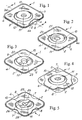
- Fig. 1 the release sheet 3 has been partially cut away to show the location of the adhesive layer 2 between the release sheet 3 and the backing layer 4.
- Figs. 2 - 5 the release sheet has been removed for the sake of clarity.
- both the release sheet 3 and the backing layer 4 are provided with a gripping tab 5 and 6, respectively, see Fig. 6 .
- the gripping tab 5 of the release sheet is intended for use when removing the release sheet 3 from the wafer 1, the release sheet 3 being provided with a coating of silicone or other release agent, such that the release sheet 3 can be removed prior to applying the thus exposed surface of the adhesive layer 2 of the wafer 1 to the peristomal skin surface of said wearer.
- the tab 6 of the backing layer 4 is intended for being gripped by the wearer or a health care person when the wafer is to be removed from said adhesion to the peristomal skin surface by peeling the wafer off starting at the region of the adhesive layer 2 adjacent the tab 6.
- the tab 6 of the backing layer 4 has been substituted by areas 7 of the backing layer 4 obtained by configuring the periphery of the adhesive layer 2 with indentations or outwardly concave portions 8 such that an area 7 can be gripped for removing the wafer 1. In this manner, relatively large gripping portions 7 are obtained allowing peeling off of the wafer from said peristomal skin surface from various directions which allows greater flexibility in the operation of removing the wafer 1 from said peristomal skin surface.
- Portions of the release sheet 3 corresponding to and overlying the portions 7 of the backing layer are intended to serve as gripping portions for removing the release sheet 3 from the adhesive layer 2 prior to applying the wafer 1 to said peristomal skin surface.
- the indentations 8 of the periphery of the adhesive layer 8 may have other shapes, particularly in connection with other shapes of the periphery of the release sheet and backing layer, be it triangular, circular or some other shape.
- the adhesive layer 2 comprises a relatively thin peripheral portion 9 and a relatively thick central portion 10.
- the central portion 10 is annular and concentric with a substantially circular stoma receiving aperture 11.
- a tapered portion 12 separates the peripheral portion 9 from the central portion 10.
- the central portion 10 has a substantially uniform thickness t1 which is at least 2.5 mm larger than the thickness t2 of the peripheral portion.
- the substantially planar annular proximal or bodyside surface13 of the central portion has a width SW, the so-called support width.
- An annular coupling ring 14 for coupling the wafer 1 to a not shown collecting bag is attached to the wafer 1 by means of an annular film 15 adhered or sealed to the ring 14 and the backing layer 4.
- the collecting bag may be attached in other ways to the wafer 1, either removably or non-removably, i.e. so-called two-piece and one-piece ostomy appliances.
- the edge portion 4a of the backing layer 4 is useful in preventing any flow or leakage of adhesive from the periphery of the adhesive layer 2 from adhering to or soiling the clothes or bed clothes of the wearer.
- the release sheet 3 has an inner edge portion 3b covering substantially the entire inner adhesive surface 16 of the stoma receiving aperture 11 such that the adhesive adjacent the surface 16 is protected against drying out and hardening. This is important as the surface 16 is intended to sealingly and supportingly surround and contact the not shown protruding stoma of the wearer as explained below.
- a number of different wafers constituting a set of wafers are provided for selecting a specific wafer of said set most suited for matching the surface topography of the peristomal skin surface and stoma of a particular wearer of an ostomy appliance comprising said specific wafer.
- the criteria for selecting said specific wafer are a combination of degree of fit of the annular central portion 10 to a moat or groove in the tissue surrounding the stoma both as regards depth and width thereof, the diameter of the stoma and the necessary degree of lateral support for said stoma.
- the wafers in one set of such wafers are therefore differentiated by varying the radius R1 of the annular central portion 10 and the radius R2 of the stoma aperture 11 (and consequently the support width SW) and the thickness t1 of the central portion 10.
- the thickness t2 of the peripheral portion is preferably constant for all wafers of the set.
- the thickness t2 is 0.85 mm.
- the thickness t2 may be larger or smaller if necessary.
- the currently preferred set of wafers of the type shown in Figs. 1 and 6 are as specified below: No. Wafer size (mm x mm) R1 (mm) t2 (mm) R2 (mm) SW (mm) 1 100 x 100 22.0 3.85 12.5 9.5 2 100 x 100 18.5 5.85 9.0 9.5 3 100 x 100 18.5 5.85 11.5 8.0 4 100 x 100 22.0 5.85 12.5 9.5 5 100 x 100 22.0 5.85 14.0 8.0 6 115 x 115 25.0 3.85 16.0 9.0 7 115 x 115 25.0 3.85 17.5 7.5 8 115 x 115 25.0 5.85 16.0 9.0 9 115 x 115 25.0 5.85 17.5 7.5 10 115 x 115 27.5 5.85 19.0 8.5
- the wafer size indicated above is in reality the size of the adhesive layer 2, while the sizes of the wafers 1 including the borders 3a and 4a with a width W of 3 mm are 6 mm larger on each side, i.e. 106 m x 106 mm and 121 mm x 121 mm, respectively.
- the set may also comprise wafers with stoma receiving apertures having a radius R2 of 7.5 mm, these wafers being intended for use by enlarging the stoma receiving aperture by cutting with scissors or the like so as to accommodate wearers with stoma diameters and/or off-center locations that are not entirely accommodated by any of the other wafers of the set.
- the set may comprise wafers with elliptical or oval stoma receiving apertures.
- the radial width of the bodyside surface 13 or SW should have a minimum size of approximately 6 mm and preferably no smaller than 7 mm and most preferably no smaller than 7.5 mm. If SW is smaller, then the central portion 10 will not support a stoma inserted in the aperture 11 sufficiently in the lateral direction.
- SW should not exceed 11 mm, preferably not be larger than 10 mm and most preferably not larger than 9.5 mm because for most configurations of a moat or groove around the stoma of ostomy patients having such a moat, the annular central portion 10 will not fit into the moat and the wafer will not afford correct support for a stoma inserted in the aperture 11 and will not fit well enough to adhere and seal against leakage of stomal fluids into contact with the peristomal skin surface and stoma of the wearer.
- Figs. 2-5 further examples of the wafer are illustrated.
- the configuration of these wafers are directed towards accomodating more differentiated surface topographies of the peristomal surface and stoma of a specific wearer.
- the thickness of the central portion 10 varies in both the radial and circumferential direction such that a ridge 20 with a peak 21 thereof is formed corresponding to a stoma surrounding moat with a depression having a matching topography.
- the thickness of the central annular portion 10 varies circumferentially such that approximately one half 22 of the central portion 10 is substantially thicker than the other half 23, for instance 6 mm and 4 mm, respectively.
- the thickness of the central annular portion 10 is uniform as in the embodiment of Fig. 1 , but the aperture 11 is oval or elliptical instead of circular so as to accommodate a stoma having an off-center location and/or a non cicular cross-section.
- the thickness of the central portion varies both in the radial and circumferential direction so that various peaks 24 and throughs 25 are formed in the surface topography of said central portion 10 corresponding to troughs and peaks of the surface topography of the peristomal surface of a specific wearer, said peristomal surface topography being registered and reproduced in inverse relationship as explained in the following with reference to Fig. 7 .
- the central portion 10 may be configured with an annular periphery as illustrated in Figs. 1-5 , but may also be configured with an irregular periphery corresponding to an irregular periphery of a moat surrounding a stoma of a specific wearer.
- All the above described configurations may be included in a set of wafers from which a specific wearer selects the wafer best suited for the special circumstances of said specific wearer. In this manner a specific wearer may identify a standard product included in said set of wafers which will function best. However the wafer may also be customized to fit the specific wearer based on the specific surface topography of the peristomal surface and stoma of said specific wearer as described in the following with reference to Fig. 7 .
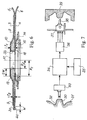
- a stoma 30 and a peristomal surface 31 with an exaggerated moat or groove 32 surrounding the stoma are illustrated in cross section.
- a scanning mechanism 33 is arranged for scanning the topography of the stoma 30, the surface 31 and the moat 32, the scanning data being transferred to a computer 34 where a digital representation of the topography of the stoma 30 and surrounding skin surface 31 and 32 is created.
- a control input device 35 causes the digital representation to be transferred to a digitally controlled activator 36 for causing a shaping device 37 with a cutting tool 38 to shape a die 39 for producing a mould for moulding the proximal bodyside surface of a wafer having a substantially perfect fit with the stoma 30 and surrounding skin surface 31, 32.
- Fig. 7 The process and equipment is illustrated in Fig. 7 in a symbolic manner and represents various possible manners of scanning the peristomal skin surface and stoma, either directly from the wearer or from a cast or impression made by means of wax or other suitable materials as well as various possible manners of providing a mould from said scanning procedure.
- the scanning procedure may take place for instance either by means of laser light or ultrasound applied directly to the wearer or by x-rays applied to a cast or impression.
- Various different procedures to achieve such scanning and conversion into a digital representation and a die or mould are known, inter alia from US patents Nos. 4,611,288 , 4,663,720 , 5,056,204 and 5,487,012 .
- the mould for such customized moulding of the proximal surface of the wafer 1 may also be produced in a conventional manner directly from a cast or impression of the peristomal surface and stoma of a specific wearer.
- the distal surface of the wafer may be provided with visual or tactile markings or guide lines that indicate the correct orientation of the wafer when being applied to the peristomal surface such that the fit between the proximal surface of the wafer and said peristomal surface is obtained.
- a sacrificial or support web 40 of PET coated with a release agent is supplied from a not shown roll, and patties 41 of a skin barrier material are deposited thereon from a container 45 thereof.
- a release web 42 with a thickness of approximately 0.15 mm and coated with a release agent such as silicone is supplied from a roll 43 thereof and preheated to approximately 120 degrees centigrade at a heating station 44 and thereafter pre-formed in a vacuum mould, the web being sucked unto the mould surface by vacuum supplied to channels 46 such that a pre-formed area of the release liner 42 is obtained.
- An indexing station 47 moves the sacrificial web 40 and the release web forward step-wise such that a precise register of webs 40 and 42 takes place relative to one another and the various treatment stations in the process train.
- the pre-formed area of the release web 42 is located centrally over a patty 41 between a lower mould part 48 and an upper mould part 49 provided with a spring loaded annular body 50 described more in detail in the following with reference to Figs. 9-13 .
- the upper mould 49 has a moulding surface very similar to and preferably identical with the moulding surface of the vacuum mould 46.
- the lower mould 48 is pressed upwards as indicated by the arrow R3 so that the patty 41 and the preformed area of the release web 42 are moulded to the desired topography of the proximal surface of the final wafer 1.
- the release web 42 has been preformed to the desired surface topography only the patty material is to be moulded by the pressure exerted by the movable mould part 48.
- the support web 40 is peeled away from the moulded patties and wound up on a roll 51, and a corona treated EMA backing web 52 is supplied from a roll 53 thereof and laminated to the distal surface of the adhesive layer (patty) at a laminating station 54.
- the finished wafers 1 are cut out at a rolling cutting station cutting through the release web 42 and the backing web 52, the cutting waste of the webs 42 and 52 being wound up on a waste roller 56.
- the wafers 1 are transported to a not shown punching station where the stoma receiving aperture 11 of the wafer 1 is formed.
- the laminating station 54 comprises two laminating rollers having a resilient surface configuration and being pressed against each other so as to apply a laminating pressure to the release web 42 and the backing web 52 such that these webs are laminated to the layer of adhesive skin barrier material 41 when passing between the two laminating rollers.
- a laminating pressure to the release web 42 and the backing web 52 such that these webs are laminated to the layer of adhesive skin barrier material 41 when passing between the two laminating rollers.
- the upper mould 49 in Fig. 8 is provided with a handle 57 and is attached to a supporting body 58 by means of two ribs 59 displaceably inserted in corresponding grooves 60 in the supporting body 58 such that the mould 49 can be substituted quickly by another mould.
- This attachment system is also utilized for the vacuum mould 46 so that this mould also may be replaced quickly.
- the annular body 50 is received displaceably in an annular groove 61 and may be displaced upwards in said groove against the force of compression springs 62. Not shown cooperating shoulders on the body 50 and the inner surface of the groove 61 prevent the body 50 from being pressed entirely out of the groove by the springs 62.
- the body 50 When a wafer 1 is being moulded in the mould 48, 49, the body 50 functions as a stop ring to prevent barrier material of the patty 41 from being pressed beyond the stop ring 50 that is kept pressed against the release web 42 and the lower mould 48 by the springs 62 during the moulding operation whereby a sharply defined periphery of the adhesive layer of the wafer is formed and no adhesive is pressed onto the ring 4a of backing material (see Fig. 6 ).
- stop ring 50 corresponding to the periphery of the adhesive layer 2 in Figs. 1-3 is shown, while the stop ring 50 shown in Fig. 11 corresponds to the periphery shown in Fig. 4 .
- the viscosity of the mouldable skin barrier material is such that substantially no skin barrier material is pressed into the air bleeding gap 63.
- the air bleeding passage 63, 64, 65 may be configured in many other ways obvious to the person skilled in the art, for instance by providing regularly spaced radial ribs having a height of approx. 0.1 mm and each extending between the inner surface 50a to the outer surface 50b of the stop ring 50.
- an alternative and currently preferred laminating station for use instead of the laminating station 54 in Fig. 8 comprises a resilient lamination pad 66 mounted on a piston 67 displaceable up and down in the direction R3 in a pneumatic cylinder 68 such that the pad 66 may exert a laminating pressure on the wafer 41 and the webs 42 and 52 for laminating them together.
- the surface portion 69 of the pad 66 that contacts the wafer 41 during the lamination process is dome shaped so that the laminating pressure is applied starting at the centre of the wafer 41 and moving outwards towards the periphery of the wafer 41.
- any air entrapped between the webs 42 and 48 will be pressed out and the stresses in the web 52 will be relaxed such that deformation of the wafer 41 by remaining stresses in the release sheet 52 is limited or eliminated.
- a resilient counter pressure pad 70 is arranged on a table 70 attached to a piston 72 displaceable up and down in the direction R4 in a pneumatic cylinder 73 such that the counter pressure pad 70 may exert a laminating counter pressure on the wafer 41 and move downwards to allow the web 52 to be released from contact with the pad 70 after the lamination stroke upwards of the pad 70.
- the lamination pad 66 is a printer's pad or tampon designed for applying printing to a surface and is made of silicone with a hardness SHORE A6 while the counter pressure pad 70 is either of neoprene or silicone with a hardness SHORE A15.
- the lamination pad or tampon used with good results was supplied by the company Morlock Tampondruck Systeme GmbH, Lise-Meitner-Str. 9, Dornstetten, Germany.
- the maximum pressure applied by the lamination pad 66 to the surface of the wafer 41 is approximately 1900 N/cm2.
- the counter pressure pad 70 may have a plane surface facing the pad 66 or this surface may be upwardly domed or convex to reinforce the effect discussed above of the laminating pressure being applied from the centre towards the periphery of the wafer 41.
- the pads 66 and 70 may be made of many other resilient materials such as rubber, latex, plastic foam material and so on, and they may be solid or hollow.
- the counter pressure pad 70 is not absolutely necessary.
- the hardness of the pads 66 and 70 may vary according to the type of skin barrier material used in the wafer 41.
- FIG. 15-18 the currently preferred configuration of the periphery of the wafer 41 is illustrated in Fig. 15-16 as compared to a not recommendable edge configuration illustrated in Figs. 17-18 .
- the edge 74 of the wafer 41 in Figs 15-16 is sharp as it tapers gradually to a very small thickness as compared to the edge 75 of the wafer 42 of Figs. 17-18 that has an appreciable thickness and is blunt giving rise to a substantially vertical peripheral region 76 of the release sheet 42 extending at substantially right angles to the web 52 where the comparable peripheral region of the release sheet in Fig. 16 forms a relatively small acute angle with the web 52.
- edge portion adjacent the edge 74 is much less prone to drying out than the edge portion adjacent the edge 75.
- the edge of the wafer 41 of Figs. 15-16 is isolated from contact with the surrounding atmosphere by the good adherence to the webs 42 and 52 and the only portion of the edge in contact with the atmosphere is the sharp edge 74.
- the adhesive layer 41 does not adhere well to the release liner 42 along the vertical portion 76 thereof, and furthermore the adhesive layer 41 does not adhere well to the carrier web 52 along an annular strip extending along and adjacent to the edge 75.
- the surrounding atmosphere is in drying out contact with a relatively large surface of the edge of the wafer giving rise to detrimental drying out of a relatively wide peripheral ring of the edge of the wafer in Figs. 17-18 .
- the laminating pressure from the laminating rollers in Fig. 8 and particularly from the laminating pad 66 in Fig. 14 is applied in a vertical direction substantially perpendicular to the plane of the carrier web 52 and substantially parallel to the vertical portion 76 of the release web 42.
- no substantial laminating pressure is applied to the end surface 75 of the adhesive wafer and the vertical portion 76 of the release sheet and therefore no substantial lamination takes place here.
- the vertical portion 76 of the relatively thick and stiff release web 42 will transmit the laminating pressure at the edge of the wafer 41 directly to the carrier web 52 as a linear force and not through the material of the wafer whereby the carrier web 52 will be pressed away from the adhesive layer instead of being laminated thereto which causes the bad adhesion between the carrier web and the wafer 41 adjacent the edge surface 75.
- the entire edge region surface of the release sheet at an angle to the direction of the laminating pressure (substantially vertical in Fig. 16 ) of between 45 and 90 degrees, preferably between 70 and 90 degrees.
- the angle between the release sheet 42 and the carrier 52 at the edge region should be between 0 and 45 degrees, preferably between 0 and 20 degrees.
- the thickness t2 will typically be between 0.8 and 1.2 mm, and one of the objectives of configuring the outer peripheral edge region of the adhesive layer with a gradually tapering thickness is to achieve as small a thickness of the layer at the edge 74 as possible.
- the thickness of the adhesive layer 41 at the edge 74 will be between 0.1 mm and 0.3 mm.
- the tapering effect may be achieved by means of a rectilinear radial profile of the release sheet 42 at the edge region instead of the circular radial profile shown in Fig. 16 .
- Figs 19-21 alternative examples of the wafer are shown with radially extending thickened portions 77 and 78 ( Figs. 19 and 20-21 , respectively) extending to the peripheral edge of the peripheral portion 2.
- the thickness t3 is preferably constant along the entire extent of the thickened portions 77 and 78 but may also vary to comply with special patient requirements.
- the object of the thickened radially extending portions is to provide regions with better adhesive properties because of the thicker layer of adhesive.
- the wafer may be oriented such that the thickened portions register with natural folds in the peristomal tissue, either permanent folds or folds occurring when sitting down.
- the wafer in Fig. 20 may be oriented such that the thickened portion is substantially horizontal so as to fit into a crease forming in the peristomal tissue when sitting or bending down.
Landscapes
- Health & Medical Sciences (AREA)
- Epidemiology (AREA)
- Nursing (AREA)
- Orthopedic Medicine & Surgery (AREA)
- Engineering & Computer Science (AREA)
- Biomedical Technology (AREA)
- Heart & Thoracic Surgery (AREA)
- Vascular Medicine (AREA)
- Life Sciences & Earth Sciences (AREA)
- Animal Behavior & Ethology (AREA)
- General Health & Medical Sciences (AREA)
- Public Health (AREA)
- Veterinary Medicine (AREA)
- Orthopedics, Nursing, And Contraception (AREA)
Claims (30)
- Scheibe (1) zum klebenden Befestigen einer Stoma-Vorrichtung auf einer peristomalen Hautoberfläche, die ein Stoma eines Trägers der Vorrichtung umgibt, wobei die Scheibe eine integral geformte klebende Schicht (2) umfasst, die aus einem feuchtigkeitsabsorbierenden und quellfähigen Hautbarrierematerial besteht und eine im Wesentlichen ebene distale Fläche aufweist, bedeckt von einer flexiblen Rückschicht (4), die sich wenigstens bis zur äußeren Peripherie der klebenden Schicht (2) erstreckt, wobei die Form der äußeren Peripherie aus nach außen konvexen oder im Wesentlichen geradlinigen Abschnitten zum Befestigen der Scheibe an einem Sammelbeutel besteht, und eine proximale körperseitige Fläche, die so konturiert ist, dass die klebende Schicht (2) einen relativ dünnen peripheren Abschnitt (9) und einen relativ dicken mittigen Abschnitt (10) aufweist, der eine Öffnung zum Aufnehmen des Stomas umgibt, wobei der mittige Abschnitt (10) im Wesentlichen gleichmäßig um die Öffnung verteilt ist, dadurch gekennzeichnet, dass der mittige Abschnitt (10) eine maximale Dicke aufweist, die wenigstens 2,5 mm größer ist als die maximale Dicke des peripheren Abschnitts, wobei die Rückschicht (4) eine Greiflasche oder einen Greifabschnitt (7) umfasst, definiert durch einen Abschnitt der Rückschicht, der frei von der klebenden Schicht (2) ist, der dadurch bereitgestellt wird, dass die klebende Schicht (2) eine Vertiefung (8) in der äußeren Peripherie aufweist, die frei von der Vertiefung auf der Rückschicht (4) angeordnet ist.
- Scheibe nach Anspruch 1, wobei der periphere Abschnitt eine Breite von wenigstens 10 mm, bevorzugt wenigstens 12 mm und am bevorzugtesten wenigstens 15 mm aufweist.
- Scheibe nach Anspruch 1 oder 2, wobei die Dicke des peripheren Abschnitts wenigstens 0,4 mm, bevorzugt wenigstens 0,5 mm, bevorzugter wenigstens 0,6 mm, noch bevorzugter 0,7 mm und am bevorzugtesten wenigstens 0,8 mm beträgt.
- Scheibe nach einem der vorhergehenden Ansprüche, wobei der mittige Abschnitt ringförmig ist.
- Scheibe nach Anspruch 4, wobei die Öffnung im Wesentlichen kreisförmig und konzentrisch mit dem kreisförmigen mittigen Abschnitt ist.
- Scheibe nach einem der Ansprüche 1-5, wobei der mittige Abschnitt eine radiale Breite von wenigstens 6 mm, bevorzugt wenigstens 7 mm und am bevorzugtesten größer oder gleich 7,5 mm aufweist.
- Scheibe nach einem der Ansprüche 1-6, wobei der mittige Abschnitt eine radiale Breite von weniger als 11 mm, bevorzugt weniger als 10 mm, am bevorzugtesten weniger als oder gleich 9,5 mm aufweist.
- Scheibe nach einem der vorhergehenden Ansprüche, wobei der mittige Abschnitt eine im Wesentlichen einheitliche Dicke aufweist.
- Scheibe nach einem der Ansprüche 1-7, wobei der mittige Abschnitt eine Dicke aufweist, die in Umfangsrichtung variiert.
- Scheibe nach einem der Ansprüche 1-7 oder 9, wobei der mittige Abschnitt eine Dicke aufweist, die in radialer Richtung variiert.
- Scheibe nach einem der vorhergehenden Ansprüche, wobei die proximale Fläche von einer an der proximalen Fläche entfernbar befestigten flexiblen Abziehfolie bedeckt ist, wobei sich die Abziehfolie wenigstens bis zur äußeren Peripherie der klebenden Schicht erstreckt.
- Scheibe nach Anspruch 11, wobei ein Randbereich der klebenden Schicht, der wenigstens 3 mm breit, bevorzugt wenigstens 6 mm breit ist und sich angrenzend an die äußere Peripherie über deren gesamte Länge erstreckt, so konfiguriert ist, dass der Winkel zwischen allen einander gegenüberliegenden Abschnitten der Abziehfolie und der den Randbereich bedeckenden flexiblen Rückschicht weniger als 45 Grad, bevorzugt weniger als 35 Grad, bevorzugter weniger als 30 Grad, noch bevorzugter weniger als 25 und am bevorzugtesten weniger als 20 Grad beträgt.
- Scheibe nach Anspruch 12, wobei die Dicke der klebenden Schicht an der äußeren Peripherie weniger als 0,5 mm, bevorzugt weniger als 0,4 mm und am bevorzugtesten weniger als 0,3 mm beträgt.
- Scheibe nach Anspruch 12, wobei ein Randbereich der klebenden Schicht, der wenigstens 3 mm breit, bevorzugt wenigstens 6 mm breit ist und sich angrenzend an die äußere Peripherie über deren gesamte Länge erstreckt, so konfiguriert ist, dass die proximale und distale Fläche in dem Randbereich in Richtung der äußeren Peripherie aufeinander zulaufen und die Dicke der klebenden Schicht an der äußeren Peripherie weniger als 0,5 mm, bevorzugt weniger als 0,4 mm und am bevorzugtesten weniger als 0,3 mm beträgt.
- Scheibe nach einem der vorhergehenden Ansprüche, wobei ein verdickter Bereich des relativ dünnen peripheren Abschnitts der klebenden Schicht eine Dicke aufweist, die im Wesentlichen größer ist als die maximale Dicke des restlichen peripheren Abschnitts.
- Scheibe nach Anspruch 15, wobei sich der verdickte Bereich zwischen dem relativ dicken mittleren Abschnitt und der äußeren Peripherie der klebenden Schicht erstreckt.
- Scheibe nach Anspruch 15 oder 16, wobei die Dicke des verdickten Bereichs einheitlich ist und zwischen 30 % und 50 % der maximalen Dicke des mittigen Abschnitts beträgt.
- Satz von wenigstens zwei Scheiben zum klebenden Befestigen einer Stoma-Vorrichtung auf einer peristomalen Hautoberfläche, die ein Stoma eines Trägers der Vorrichtung umgibt, wobei jede Scheibe des Satzes den Ansprüchen 1-17 entspricht und eine klebende Schicht umfasst, die aus einem feuchtigkeitsabsorbierenden und quellfähigen Hautbarrierematerial besteht und eine im Wesentlichen ebene distale Fläche aufweist, bedeckt von einer flexiblen Rückschicht, die sich wenigstens bis zur äußeren Peripherie der klebenden Schicht erstreckt, um die Scheiben an einem Sammelbeutel zu befestigen, und eine proximale körperseitige Fläche, die so konturiert ist, dass die klebende Schicht einen relativ dünnen peripheren Abschnitt und einen relativ dicken mittigen Abschnitt aufweist, der eine Öffnung zum Aufnehmen des Stomas umgibt, wobei der mittige Abschnitt im Wesentlichen gleichmäßig um die Öffnung verteilt ist und eine maximale Dicke aufweist, die wenigstens 2,5 mm größer ist als die maximale Dicke des peripheren Abschnitts, wobei sich die einzelnen Scheiben des Satzes dadurch voneinander unterscheiden, dass die Flächentopographie des mittigen Abschnitts unterschiedlich ist.
- Satz von Scheiben nach Anspruch 18, wobei wenigstens zwei der Scheiben des Satzes einem der Ansprüche 2-17 entsprechen.
- Satz von Scheiben nach Anspruch 18 oder 19, wobei sich wenigstens zwei Scheiben dadurch voneinander unterscheiden, dass die Größe und/oder Form der das Stoma aufnehmenden Öffnung unterschiedlich ist.
- Verfahren zur Herstellung einer Scheibe zum klebenden Befestigen einer Stoma-Vorrichtung auf einer peristomalen Hautoberfläche, die ein Stoma eines Trägers der Vorrichtung umgibt, wobei die Scheibe eine integral geformte klebende Schicht umfasst, die aus einem feuchtigkeitsabsorbierenden und quellfähigen Hautbarrierematerial besteht und eine im Wesentlichen ebene distale Fläche aufweist, bedeckt von einer flexiblen Rückschicht, die sich wenigstens bis zur äußeren Peripherie der klebenden Schicht erstreckt, wobei die Form der äußeren Peripherie aus nach außen konvexen oder im Wesentlichen geradlinigen Abschnitten zum Befestigen der Scheibe an einem Sammelbeutel besteht, und eine proximale konturierte körperseitige Fläche mit einer ersten Flächentopografie, so dass die klebende Schicht einen relativ dünnen peripheren Abschnitt und einen relativ dicken mittigen Abschnitt aufweist, der eine Öffnung zum Aufnehmen des Stomas umgibt, wobei die proximale Fläche von einer Abziehschicht bedeckt ist und der mittige Abschnitt eine maximale Dicke aufweist, die wenigstens 2,5 mm größer ist als die maximale Dicke des peripheren Abschnitts, wobei die Rückschicht (4) eine Greiflasche (6) oder einen Greifabschnitt (7) umfasst, definiert durch einen Abschnitt der Rückschicht, der frei von der klebenden Schicht (2) ist, der dadurch bereitgestellt wird, dass die klebende Schicht (2) eine Vertiefung (8) in der äußeren Peripherie aufweist, die frei von der Vertiefung auf der Rückschicht (4) angeordnet ist, wobei das Verfahren die folgenden Schritte umfasst: -Bereitstellen einer mit einer ersten Formaushöhlung ausgestatteten ersten Form zum Vorformen der Abziehschicht mit einer zweiten Flächentopographie, die ähnlich wie die oder bevorzugt im Wesentlichen identisch mit der ersten Flächentopographie ist, wobei die Aushöhlung mit Saugöffnungen ausgestattet ist, die mit einer Vakuumquelle kommunizieren, eine zweite Form bereitstellend, um die klebende Schicht mit einem ersten und einem zweiten Teil, die dafür ausgerichtet sind, gegeneinander gepresst zu werden, zu formen, wobei der erste Teil mit einer zweiten Formaushöhlung ausgestattet ist, um die erste Flächentopographie der klebenden Schicht zu definieren, eine im Wesentlichen kontinuierliche Zufuhr einer Opferschicht bereitstellend, -Anordnen des Hautbarrierematerials auf der Opferschicht, eine im Wesentlichen kontinuierliche Zufuhr der Abziehschicht bereitstellend, -Erhitzen eines Bereichs der Abziehschicht, um deren Verformbarkeit zu verbessern, -Positionieren des erhitzten Bereichs im Einklang mit der ersten Formaushöhlung, Anwenden von Vakuum auf die Saugöffnungen, so dass der Bereich in die Aushöhlung gesaugt und dabei verformt wird, so dass der Bereich mit einer dritten Flächentopographie ausgestattet ist, die im Wesentlichen mit der zweiten Flächentopographie identisch ist, -Aufheben der Vakuumanwendung, -Verschieben des Bereichs im Einklang mit der zweiten Formaushöhlung, so dass die dritte Flächentopographie mit der zweiten Flächentopographie, -Verschieben eines Abschnitts der Opferschicht mit Barrierematerial darauf im Einklang mit der zweiten Formaushöhlung, so dass sich der Bereich zwischen dem Abschnitt und der zweiten Formaushöhlung befindet, und Pressen des zweiten Teils gegen den ersten Teil, so dass der Bereich und der Abschnitt in die zweite Formaushöhlung gepresst werden.
- Verfahren zum Laminieren einer Scheibe nach einem der Ansprüche 1-17, wobei das Verfahren die folgenden Schritte umfasst: -Aufbringen der flexiblen Rückschicht auf die distale Fläche, -Aufbringen einer flexiblen Abziehfolie auf die proximale Fläche, -Bereitstellen eines elastischen Laminierungspolsters oder -tampons, das oder der dafür ausgelegt ist, in eine Laminierungsrichtung vor und zurück verschoben zu werden und in Laminierungsrichtung Laminierungsdruck auszuüben, -Bereitstellen einer ebenen Gegendruckfläche mit im Wesentlichen rechten Winkeln zur Laminierungsrichtung, - Platzieren der Scheibe auf der Gegendruckfläche, wobei die ebene Rückschicht an die Gegendruckfläche anstößt, und -Verschieben des Laminierungspolsters in Laminierungsrichtung, so dass von dem Laminierungspolster Laminierungsdruck auf die gesamte distale Fläche der Scheibe ausgeübt wird.
- Verfahren nach Anspruch 22, wobei die Fläche des zum Ausüben des Laminierungsdrucks auf die Scheibe bestimmten Laminierungspolsters in Laminierungsrichtung gewölbt oder konvex ist.
- Verfahren nach Anspruch 22 oder 23, wobei das Laminierungspolster aus Silikon besteht.
- Verfahren nach einem der Ansprüche 22-24, wobei das Laminierungspolster ein zum Drucken auf eine Fläche entwickeltes Druckpolster ist.
- Verfahren nach einem der Ansprüche 22-25, wobei das Laminierungspolster eine Härte zwischen SHORE A3 und SHORE A9, bevorzugt zwischen SHORE A5 und SHORE A7 hat.
- Verfahren nach einem der Ansprüche 22-26, wobei die Gegendruckfläche angepasst ist, um in Laminierungsrichtung vor und zurück verschoben zu werden.
- Verfahren nach einem der Ansprüche 22-27, wobei die Gegendruckfläche die Fläche eines elastischen Gegendruckpolsters ist.
- Verfahren nach Anspruch 28, wobei das Gegendruckpolster aus Silikon oder Neopren besteht.
- Verfahren nach Anspruch 28 oder 29, wobei die Fläche des zum Anstoßen an die Rückschicht bestimmten Gegendruckpolsters in die Gegenrichtung zu der Laminierungsrichtung gewölbt oder konvex ist.
Priority Applications (1)
| Application Number | Priority Date | Filing Date | Title |
|---|---|---|---|
| EP10183729A EP2298251A3 (de) | 2002-03-11 | 2003-03-11 | Weiche konvexe klebende scheibe |
Applications Claiming Priority (3)
| Application Number | Priority Date | Filing Date | Title |
|---|---|---|---|
| US10/095,223 US20030171737A1 (en) | 2002-03-11 | 2002-03-11 | Soft convex adhesive wafer |
| US95223 | 2002-03-11 | ||
| PCT/DK2003/000148 WO2003075808A1 (en) | 2002-03-11 | 2003-03-11 | Soft convex adhesive wafer |
Related Child Applications (1)
| Application Number | Title | Priority Date | Filing Date |
|---|---|---|---|
| EP10183729A Division-Into EP2298251A3 (de) | 2002-03-11 | 2003-03-11 | Weiche konvexe klebende scheibe |
Publications (2)
| Publication Number | Publication Date |
|---|---|
| EP1485048A1 EP1485048A1 (de) | 2004-12-15 |
| EP1485048B1 true EP1485048B1 (de) | 2016-06-01 |
Family
ID=27804266
Family Applications (2)
| Application Number | Title | Priority Date | Filing Date |
|---|---|---|---|
| EP10183729A Withdrawn EP2298251A3 (de) | 2002-03-11 | 2003-03-11 | Weiche konvexe klebende scheibe |
| EP03714706.3A Expired - Lifetime EP1485048B1 (de) | 2002-03-11 | 2003-03-11 | Weiche konvexe klebende scheibe |
Family Applications Before (1)
| Application Number | Title | Priority Date | Filing Date |
|---|---|---|---|
| EP10183729A Withdrawn EP2298251A3 (de) | 2002-03-11 | 2003-03-11 | Weiche konvexe klebende scheibe |
Country Status (5)
| Country | Link |
|---|---|
| US (2) | US20030171737A1 (de) |
| EP (2) | EP2298251A3 (de) |
| JP (1) | JP4391828B2 (de) |
| AU (1) | AU2003218957A1 (de) |
| WO (1) | WO2003075808A1 (de) |
Cited By (2)
| Publication number | Priority date | Publication date | Assignee | Title |
|---|---|---|---|---|
| US11918508B1 (en) | 2022-09-01 | 2024-03-05 | Hollister Incorporated | Ostomy appliance for providing customized and localized convex support |
| US12097142B2 (en) | 2022-09-01 | 2024-09-24 | Hollister Incorporated | Ostomy appliance with customizable barrier ring for localized convex support |
Families Citing this family (103)
| Publication number | Priority date | Publication date | Assignee | Title |
|---|---|---|---|---|
| US6916312B2 (en) * | 2001-08-31 | 2005-07-12 | The Procter & Gamble Company | Applicator for excreta management device |
| US6929627B2 (en) * | 2002-04-30 | 2005-08-16 | James L. Mahoney | Support device for ostomy appliance |
| SE0201907D0 (sv) * | 2002-06-19 | 2002-06-19 | Atos Medical Ab | Plaster for tracheostoma valves |
| US20040087920A1 (en) * | 2002-10-28 | 2004-05-06 | Etheredge Robert W. | Ostomy device kit |
| USD516212S1 (en) * | 2003-05-13 | 2006-02-28 | Atos Medical Ab | Tracheostoma plaster device |
| NZ555240A (en) * | 2004-09-16 | 2008-10-31 | Bristol Myers Squibb Co | Seal for controlled evacuation ostomy appliance |
| WO2006035014A2 (en) * | 2004-09-29 | 2006-04-06 | Coloplast A/S | A resalable ostomy appliance |
| US20080275327A1 (en) * | 2005-03-09 | 2008-11-06 | Susanne Holm Faarbaek | Three-Dimensional Adhesive Device Having a Microelectronic System Embedded Therein |
| GB2428381A (en) * | 2005-06-14 | 2007-01-31 | Welland Medical Ltd | Improved adhesive pads for ostomy bags |
| CA2690968A1 (en) * | 2007-06-19 | 2008-12-24 | Coloplast A/S | Multi-layered adhesive appliance |
| EP2173287A1 (de) * | 2007-07-06 | 2010-04-14 | Coloplast A/S | Haftkomponente für stomavorrichtungen |
| EP2187846B1 (de) * | 2007-08-10 | 2015-05-06 | Coloplast A/S | Fäkalsammelvorrichtung |
| EP2315561B1 (de) * | 2008-07-18 | 2016-09-28 | Coloplast A/S | Eine schichtweise klebekonstruktion umfassende einrichtung zum sammeln von körperschlacken |
| CN102215789B (zh) * | 2008-11-12 | 2014-07-16 | 科洛普拉斯特公司 | 控制一种用于造瘘术器具中的皮肤板的弯曲 |
| CA2742900A1 (en) * | 2008-12-08 | 2010-06-17 | Esben Stroebech | A body waste collecting device comprising a layered adhesive construction with a film layer |
| US9549840B2 (en) * | 2008-12-18 | 2017-01-24 | Coloplast A/S | Ostomy appliance with a release liner having a predefined folding line |
| US8211073B2 (en) * | 2009-06-17 | 2012-07-03 | Hollister Incorporated | Ostomy faceplate having moldable adhesive wafer with diminishing surface undulations |
| CN102811683B (zh) * | 2010-03-19 | 2015-11-25 | 科洛普拉斯特公司 | 具有可塑中心部分的造口术基板 |
| CN102753122A (zh) * | 2010-04-12 | 2012-10-24 | 莫恩里克保健公司 | 用于造口装置的身体附着片 |
| PL2605733T3 (pl) * | 2010-08-16 | 2015-12-31 | Coloplast As | Urządzenie stomijne |
| RU2571326C2 (ru) | 2010-12-17 | 2015-12-20 | Колопласт А/С | Конвексное опорное устройство для устройства стомы |
| RU2013133863A (ru) * | 2010-12-20 | 2015-01-27 | Евромед Инк. | Устройство для стомы |
| USD683451S1 (en) | 2011-03-07 | 2013-05-28 | Hollister Incorporated | Convex barrier ring with tapered peripheral end portions for ostomy appliance |
| US8672908B2 (en) * | 2011-03-07 | 2014-03-18 | Hollister Incorporated | Convex barrier ring |
| WO2013029623A1 (en) * | 2011-08-29 | 2013-03-07 | Coloplast A/S | Ostomy base plate having discreet pulling tab |
| NL2007326C2 (en) * | 2011-09-01 | 2013-03-04 | Stichting Katholieke Univ | Automatic tracheostoma speech valve (atsv) fixation brace. |
| DE102011112517A1 (de) * | 2011-09-07 | 2013-03-07 | Gunther Martin | Aufnahmevorrichtung für Körperausscheidungen |
| EP2601915A1 (de) * | 2011-12-08 | 2013-06-12 | Hollister Incorporated | Ostomiemesswerkzeug |
| EP2928421B1 (de) * | 2012-12-06 | 2017-05-31 | Coloplast A/S | Adaptierbare stomagrundplatte |
| WO2014117778A1 (en) | 2013-01-29 | 2014-08-07 | Coloplast A/S | An ostomy appliance |
| RU2666987C1 (ru) | 2013-12-18 | 2018-09-13 | Колопласт А/С | Приспособляемая базовая пластина для стомы |
| US10531977B2 (en) | 2014-04-17 | 2020-01-14 | Coloplast A/S | Thermoresponsive skin barrier appliances |
| US10034793B2 (en) | 2014-06-16 | 2018-07-31 | Sarasota Medical Products, Inc. | Coupling systems including interlocking male and female members |
| EP2957268A1 (de) * | 2014-06-17 | 2015-12-23 | University of Limerick | Ostomiebeutelsystem |
| WO2016113598A1 (en) * | 2015-01-15 | 2016-07-21 | Zhang Shun | Absorbent ostomy wafer, waste bag and belt assembly |
| AU2016211382B2 (en) * | 2015-01-28 | 2019-10-10 | Hollister Incorporated | Adhesive for moist tissue and peristomal device made using the same |
| EP3270835B1 (de) | 2015-03-16 | 2019-05-08 | Coloplast A/S | Ostomievorrichtung |
| RU2717713C2 (ru) * | 2015-03-20 | 2020-03-25 | Колопласт А/С | Набор для устройства для стомы |
| US11141100B2 (en) | 2015-12-23 | 2021-10-12 | Coloplast A/S | Moisture assessment system and method for wound care |
| ES2991137T3 (es) * | 2015-12-24 | 2024-12-02 | Tan Jason Jit Sun | Pieza de inserción para estoma personalizable |
| CN108601679B (zh) * | 2016-02-04 | 2021-04-06 | 阿托斯医疗公司 | 气管造口装置保持器 |
| USD862691S1 (en) | 2016-05-12 | 2019-10-08 | Marlen Manufacturing And Development Co. | Ostomy pouch |
| US10945873B2 (en) * | 2016-05-12 | 2021-03-16 | Marlen Manufacturing And Development Co. | Multi-petaled mounting members for ostomy pouches |
| EP3454797B1 (de) * | 2016-05-12 | 2022-02-09 | Marlen Manufacturing And Development Co. | Montageanordnungen für stomavorrichtungen mit einem haftenden hautbarriereelement mit einem mehrblättrigen aussenumfang |
| CA3037598C (en) * | 2016-10-03 | 2022-05-10 | Hollister Incorporated | Adjustable convexity ostomy barrier |
| EP3912602B1 (de) * | 2017-04-10 | 2024-08-21 | Coloplast A/S | Körperseitiges element eines ostomiegeräts |
| US20200146944A1 (en) * | 2017-04-25 | 2020-05-14 | The Regents Of The University Of Colorado, A Body Corporate | Dressing for enteral and vesical access devices and related methods |
| EP3706674B1 (de) * | 2017-11-08 | 2022-01-05 | Coloplast A/S | Komplementäres materialelement für eine stomavorrichtung |
| US11534323B2 (en) | 2017-12-22 | 2022-12-27 | Coloplast A/S | Tools and methods for placing a medical appliance on a user |
| WO2019120429A1 (en) | 2017-12-22 | 2019-06-27 | Coloplast A/S | Data collection schemes for an ostomy appliance and related methods |
| LT3727219T (lt) | 2017-12-22 | 2023-09-11 | Coloplast A/S | Drėgmės aptikimo pagrindo plokštė ostomijos prietaisui ir drėgmės sklidimo pagrindo plokštėje ir (arba) jutiklių montavimo dalyje nustatymo sistema |
| US10849781B2 (en) | 2017-12-22 | 2020-12-01 | Coloplast A/S | Base plate for an ostomy appliance |
| US10799385B2 (en) | 2017-12-22 | 2020-10-13 | Coloplast A/S | Ostomy appliance with layered base plate |
| WO2019120451A1 (en) | 2017-12-22 | 2019-06-27 | Coloplast A/S | Base plate and a sensor assembly part for an ostomy appliance and a method for manufacturing a base plate and sensor assembly part |
| WO2019120452A1 (en) | 2017-12-22 | 2019-06-27 | Coloplast A/S | Coupling part with a hinge for an ostomy base plate and sensor assembly part |
| WO2019120442A1 (en) | 2017-12-22 | 2019-06-27 | Coloplast A/S | Sensor assembly part and a base plate for an ostomy appliance and a device for connecting to a base plate or a sensor assembly part |
| WO2019120448A1 (en) * | 2017-12-22 | 2019-06-27 | Coloplast A/S | System including a skin-engageable element of an ostomy appliance |
| LT3727227T (lt) | 2017-12-22 | 2023-07-25 | Coloplast A/S | Ostomijos prietaiso pagrindo plokštė ir pagrindo plokštės jutiklių montavimo dalis ir pagrindo plokštės ir jutiklių montavimo dalies gamybos būdas |
| LT3727240T (lt) | 2017-12-22 | 2022-03-10 | Coloplast A/S | Ostomijos sistemos papildomi įrenginiai ir susiję būdai veikimo būsenai perduoti |
| US10500084B2 (en) | 2017-12-22 | 2019-12-10 | Coloplast A/S | Accessory devices of an ostomy system, and related methods for communicating leakage state |
| WO2019120445A1 (en) | 2017-12-22 | 2019-06-27 | Coloplast A/S | Base plate and sensor assembly of an ostomy system having a leakage sensor |
| EP4042985B1 (de) | 2017-12-22 | 2025-10-29 | Coloplast A/S | Verarbeitungsschemata für ein stomasystem, überwachungsvorrichtung für eine stomavorrichtung und zugehörige verfahren |
| US11627891B2 (en) | 2017-12-22 | 2023-04-18 | Coloplast A/S | Calibration methods for medical appliance tools |
| EP4180010A1 (de) | 2017-12-22 | 2023-05-17 | Coloplast A/S | Sensorbauteil eines stomasystems mit feuchtigkeitssensor |
| WO2019120447A1 (en) | 2017-12-22 | 2019-06-27 | Coloplast A/S | Sensor assembly part, base plate and monitor device of an ostomy system and associated method |
| JP7462558B2 (ja) | 2017-12-22 | 2024-04-05 | コロプラスト アクティーゼルスカブ | 角度的漏出検出を用いるオストミーシステム及びモニタデバイス |
| WO2019120441A1 (en) | 2017-12-22 | 2019-06-27 | Coloplast A/S | Sensor assembly part and a base plate for an ostomy appliance and a method for manufacturing a sensor assembly part and a base plate |
| AU2018386861B2 (en) | 2017-12-22 | 2024-03-14 | Coloplast A/S | Ostomy appliance with angular leakage detection |
| EP4640191A3 (de) | 2017-12-22 | 2026-01-07 | Coloplast A/S | Datenübertragungsschemata für ein stomasystem, überwachungsvorrichtung für eine stomavorrichtung und zugehörige verfahren |
| WO2019120425A1 (en) | 2017-12-22 | 2019-06-27 | Coloplast A/S | Ostomy appliance system, monitor device, and method of monitoring an ostomy appliance |
| US11865029B2 (en) | 2017-12-22 | 2024-01-09 | Coloplast A/S | Monitor device of a medical system having a connector for coupling to both a base plate and an accessory device |
| EP4032510B1 (de) | 2017-12-22 | 2025-07-09 | Coloplast A/S | Basisplatte mit selektiven sensorpunkten und verfahren zu deren herstellung |
| JP7472022B2 (ja) | 2017-12-22 | 2024-04-22 | コロプラスト アクティーゼルスカブ | オストミー装具のためのベースプレート、モニタデバイス及びオストミー装具のためのシステム |
| US11931285B2 (en) | 2018-02-20 | 2024-03-19 | Coloplast A/S | Sensor assembly part and a base plate for a medical appliance and a device for connecting to a base plate and/or a sensor assembly part |
| EP4631480A3 (de) | 2018-02-20 | 2025-12-10 | Coloplast A/S | Zubehörgeräte für ein stomasystem und zugehörige verfahren zum wechseln einer stomavorrichtung auf der grundlage eines zukünftigen betriebszustands |
| US12208029B2 (en) | 2018-02-20 | 2025-01-28 | Coloplast A/S | Base plate having a mechanical and electrical connector |
| EP4079266B1 (de) | 2018-03-15 | 2024-06-05 | Coloplast A/S | Verfahren zur verwaltung der resttragezeit einer stomavorrichtung und zugehörige zubehörgeräte |
| WO2019174697A1 (en) | 2018-03-15 | 2019-09-19 | Coloplast A/S | Apparatus and methods for navigating ostomy appliance user to changing room |
| CN111885984B (zh) | 2018-03-15 | 2023-08-04 | 科洛普拉斯特公司 | 基于传感器数据来确定造口术器具穿戴时间的设备和方法 |
| EP4374776A3 (de) | 2018-03-15 | 2024-09-11 | Coloplast A/S | Vorrichtung und verfahren zur bestimmung der tragezeit eines stomas basierend auf standortdaten |
| US11903728B2 (en) | 2018-03-15 | 2024-02-20 | Coloplast A/S | Methods of configuring medical notifications and related accessory devices |
| WO2020035121A1 (en) | 2018-08-15 | 2020-02-20 | Coloplast A/S | Accessory device of an ostomy system and related methods for issue identification |
| CA3121115C (en) | 2018-11-27 | 2023-10-31 | The Regents Of The University Of Colorado, A Body Corporate | Securement assembly for enteral and vesical access devices and related methods |
| WO2020125906A1 (en) | 2018-12-20 | 2020-06-25 | Coloplast A/S | Ostomy condition classification with masking, devices and related methods |
| EP3897482B1 (de) | 2018-12-20 | 2025-07-16 | Coloplast A/S | Stomazustandsklassifizierung mit bilddatentransformation, vorrichtungen und zugehörige verfahren |
| AU2020214965B2 (en) | 2019-01-31 | 2025-09-18 | Coloplast A/S | A sensor patch for an ostomy appliance |
| KR102807748B1 (ko) | 2019-01-31 | 2025-05-14 | 컬러플라스트 에이/에스 | 스토마용 센서 패치 |
| US12232998B2 (en) | 2019-01-31 | 2025-02-25 | Coloplast A/S | Application of a stomal sensor patch |
| US11612512B2 (en) | 2019-01-31 | 2023-03-28 | Coloplast A/S | Moisture detecting base plate for an ostomy appliance and a system for determining moisture propagation in a base plate and/or a sensor assembly part |
| US12558250B2 (en) | 2019-01-31 | 2026-02-24 | Coloplast A/S | Base plate and a sensor assembly part for an ostomy appliance |
| EP3930642B1 (de) | 2019-02-28 | 2023-10-25 | Coloplast A/S | Sensorpflaster zur befestigung an einer grundplatte |
| USD938579S1 (en) * | 2019-03-21 | 2021-12-14 | Salts Healthcare Limited | Ostomy bag |
| US20220168131A1 (en) * | 2019-04-01 | 2022-06-02 | Coloplast A/S | A barrier ring |
| EP3946178B1 (de) * | 2019-04-25 | 2025-03-26 | ConvaTec Technologies Inc. | Ostomiescheiben mit perforierter kammer |
| AU2020262496A1 (en) * | 2019-04-25 | 2021-11-18 | Convatec Technologies Inc. | Ostomy wafers incorporating adhesives, ostomy devices including the same, and methods of applying |
| WO2020220025A1 (en) * | 2019-04-25 | 2020-10-29 | Convatec Technologies Inc. | Ostomy wafers incorporating adhesives and foam layers, devices including the same, and methods of applying |
| EP3958801B1 (de) | 2019-04-26 | 2024-08-21 | Coloplast A/S | Sensorpflaster zur befestigung an einer grundplatte |
| DK202070555A1 (en) * | 2019-08-28 | 2021-03-31 | Coloplast As | Ostomy base plate and methods of preventing contamination of the adhesive of the base plate |
| EP4069163A1 (de) * | 2019-12-06 | 2022-10-12 | Hollister Incorporated | Weiches konvexes stoma |
| EP4135636B1 (de) | 2020-04-14 | 2024-12-04 | Coloplast A/S | Überwachungsvorrichtung für ein körperpflegesystem |
| US12472089B2 (en) | 2020-12-23 | 2025-11-18 | Coloplast A/S | Ostomy product adhesive securing member |
| US12622802B2 (en) * | 2023-04-12 | 2026-05-12 | David Patrick Ross | Apparatus and method of using a urostomy belt |
| WO2025027285A1 (en) * | 2023-07-28 | 2025-02-06 | Convatec Limited | A release layer/backing laver for an ostomy body fitment |
Citations (2)
| Publication number | Priority date | Publication date | Assignee | Title |
|---|---|---|---|---|
| EP0264299A2 (de) * | 1986-10-17 | 1988-04-20 | Coloplast A/S | Wundverband |
| EP0806210A2 (de) * | 1996-04-30 | 1997-11-12 | Hollister Incorporated | Klebende Scheibe mit geprägter hautberührender Oberfläche |
Family Cites Families (34)
| Publication number | Priority date | Publication date | Assignee | Title |
|---|---|---|---|---|
| US4253460A (en) * | 1979-07-27 | 1981-03-03 | E. R. Squibb & Sons, Inc. | Ostomy adhesive |
| US4534767A (en) * | 1980-09-08 | 1985-08-13 | Hollister Incorporated | Protective sealing composition in molded form |
| US4578065A (en) * | 1981-06-10 | 1986-03-25 | Hollister Incorporated | Protective sealing composition in molded form |
| FR2525103B1 (fr) * | 1982-04-14 | 1985-09-27 | Duret Francois | Dispositif de prise d'empreinte par des moyens optiques, notamment en vue de la realisation automatique de protheses |
| US4663720A (en) * | 1984-02-21 | 1987-05-05 | Francois Duret | Method of and apparatus for making a prosthesis, especially a dental prosthesis |
| US4738257A (en) * | 1986-06-11 | 1988-04-19 | Hollister Incorporated | Occlusive wound care dressing |
| US4793337A (en) * | 1986-11-17 | 1988-12-27 | E. R. Squibb & Sons, Inc. | Adhesive structure and products including same |
| US4762738A (en) * | 1986-12-22 | 1988-08-09 | E. R. Squibb & Sons, Inc. | Means for disposal of articles by flushing and ostomy pouches particularly suited for such disposal |
| CH677570A5 (de) * | 1989-05-17 | 1991-05-31 | Ascom Audiosys Ag | |
| DE4015186A1 (de) * | 1990-05-11 | 1991-11-21 | Ganz Franz Josef Dr Med | Verfahren zur stomagerechten anpassung einer stomaversorgungsvorrichtung |
| GB9020218D0 (en) * | 1990-09-15 | 1990-10-24 | Smiths Industries Plc | Medico-surgical collection bag assemblies |
| US5133821A (en) * | 1990-11-19 | 1992-07-28 | Jensen Ole R | Method for contouring hydrocolloid wound dressings |
| US5487012A (en) * | 1990-12-21 | 1996-01-23 | Topholm & Westermann Aps | Method of preparing an otoplasty or adaptive earpiece individually matched to the shape of an auditory canal |
| US5389066A (en) * | 1991-04-15 | 1995-02-14 | Rhame, Jr.; Robert W. | Atraumatic eye patch |
| US5249581A (en) * | 1991-07-15 | 1993-10-05 | Horbal Mark T | Precision bone alignment |
| US5346482A (en) * | 1993-04-02 | 1994-09-13 | Hollister Incorporated | Two-piece ostomy appliance having flushable pouch and faceplate with protective collar |
| US5588428A (en) * | 1993-04-28 | 1996-12-31 | The University Of Akron | Method and apparatus for non-invasive volume and texture analysis |
| US5496320A (en) * | 1994-02-14 | 1996-03-05 | Moskovich; Ronald | Moskovich clamps for interlaminar cervical fixation |
| US5496296A (en) * | 1994-06-06 | 1996-03-05 | Dansac A/S | Ostomy appliance with extrudable gasket |
| US5429625A (en) * | 1994-06-27 | 1995-07-04 | Dansac A/S | Two-piece ostomy appliance with pouch-mounted pressure ring |
| US6051249A (en) * | 1995-01-27 | 2000-04-18 | Coloplast A/S | Dressing having a three-dimensional part and processes for the preparation of such a dressing |
| US5609585A (en) * | 1995-08-01 | 1997-03-11 | Hollister Incorporated | Wafer having adhesive skin barrier layer |
| US5781652A (en) * | 1995-09-15 | 1998-07-14 | Pratt; Greg | Three-dimensional support socket digitizing system and method |
| US5682886A (en) * | 1995-12-26 | 1997-11-04 | Musculographics Inc | Computer-assisted surgical system |
| NZ314490A (en) * | 1996-04-10 | 1998-12-23 | Bristol Myers Squibb Co | Customised ostomy device and manufacture thereof - measuring, electronic recording and fabricating an adhesive wafer and collection pouch |
| US5771310A (en) * | 1996-12-30 | 1998-06-23 | Shriners Hospitals For Children | Method and apparatus for recording three-dimensional topographies |
| US5730736A (en) * | 1996-04-30 | 1998-03-24 | Dansac A/S | Ostomy appliance and contoured adhesive wafer therefor |
| US5824111A (en) * | 1997-01-31 | 1998-10-20 | Prosthetic Design, Inc. | Method for fabricating a prosthetic limb socket |
| EP0882437A3 (de) * | 1997-06-04 | 1998-12-16 | Coloplast A/S | Ostomievorrichtung mit einer konkaven/konvexen Front-Platte |
| US5879292A (en) * | 1997-10-09 | 1999-03-09 | Edward A. Sternberg | Bandage including data acquisition components |
| US6136027A (en) * | 1997-10-22 | 2000-10-24 | Otto Bock U.S., Inc. | Custom prosthetic devices and methods of fabricating them using visible reverse imaging |
| US6106507A (en) * | 1998-06-11 | 2000-08-22 | Hollister Incorporated | Ostomy appliance faceplate with barrier layer, extended covering layer, and unitary protective release sheet and method of making |
| US6093276A (en) * | 1998-06-11 | 2000-07-25 | Hollister Incorporated | In-line method of manufacture of ostomy appliance faceplate |
| US6569134B1 (en) * | 2000-06-14 | 2003-05-27 | Hollister Incorporated | Reformable convex adapter for ostomy appliance and method of use |
-
2002
- 2002-03-11 US US10/095,223 patent/US20030171737A1/en not_active Abandoned
-
2003
- 2003-03-11 WO PCT/DK2003/000148 patent/WO2003075808A1/en not_active Ceased
- 2003-03-11 JP JP2003574085A patent/JP4391828B2/ja not_active Expired - Lifetime
- 2003-03-11 AU AU2003218957A patent/AU2003218957A1/en not_active Abandoned
- 2003-03-11 EP EP10183729A patent/EP2298251A3/de not_active Withdrawn
- 2003-03-11 EP EP03714706.3A patent/EP1485048B1/de not_active Expired - Lifetime
- 2003-09-11 US US10/659,823 patent/US20040106908A1/en not_active Abandoned
Patent Citations (2)
| Publication number | Priority date | Publication date | Assignee | Title |
|---|---|---|---|---|
| EP0264299A2 (de) * | 1986-10-17 | 1988-04-20 | Coloplast A/S | Wundverband |
| EP0806210A2 (de) * | 1996-04-30 | 1997-11-12 | Hollister Incorporated | Klebende Scheibe mit geprägter hautberührender Oberfläche |
Cited By (2)
| Publication number | Priority date | Publication date | Assignee | Title |
|---|---|---|---|---|
| US11918508B1 (en) | 2022-09-01 | 2024-03-05 | Hollister Incorporated | Ostomy appliance for providing customized and localized convex support |
| US12097142B2 (en) | 2022-09-01 | 2024-09-24 | Hollister Incorporated | Ostomy appliance with customizable barrier ring for localized convex support |
Also Published As
| Publication number | Publication date |
|---|---|
| EP1485048A1 (de) | 2004-12-15 |
| US20040106908A1 (en) | 2004-06-03 |
| JP4391828B2 (ja) | 2009-12-24 |
| AU2003218957A1 (en) | 2003-09-22 |
| WO2003075808A1 (en) | 2003-09-18 |
| JP2005519674A (ja) | 2005-07-07 |
| EP2298251A3 (de) | 2011-05-11 |
| EP2298251A2 (de) | 2011-03-23 |
| US20030171737A1 (en) | 2003-09-11 |
Similar Documents
| Publication | Publication Date | Title |
|---|---|---|
| EP2298251A2 (de) | Weiche konvexe klebende Scheibe | |
| EP2497449A2 (de) | Konvexer Sperrring | |
| EP3675953B1 (de) | Vorrichtungen und verfahren zur kontaktierung von lebendem gewebe | |
| CN1852691B (zh) | 伤口敷料及其生产方法 | |
| CN101431969B (zh) | 粘贴片 | |
| EP3849480B1 (de) | Konvexe stoma-barriere und verfahren zur herstellung von konvexen stoma-barrieren mit unterschiedlicher weichheit | |
| AU2020262496A1 (en) | Ostomy wafers incorporating adhesives, ostomy devices including the same, and methods of applying | |
| EP3946180A1 (de) | Stoma-wafer mit klebstoffen und schaumschichten, vorrichtungen damit und anwendungsverfahren | |
| CA3041083C (en) | CONVEX STOMY BARRIER | |
| JP2002537067A (ja) | オストミー装具 | |
| US3373745A (en) | Medical device such as for ileostomy and colostomy | |
| US20250228695A1 (en) | Ostomy barrier appliance with self-activating adjustable convexity | |
| US8296971B2 (en) | Device for relieving pressure from a selected area of an animal's skin and methods of fabricating and applying the same | |
| JP7556184B1 (ja) | ストーマテンプレートおよび特注のオストミー皮膚バリアの製造方法 | |
| EP1586288B1 (de) | Ostomievorrichtung | |
| CA3108574C (en) | Convex ostomy barrier and method of forming convex ostomy barriers of various softness |
Legal Events
| Date | Code | Title | Description |
|---|---|---|---|
| PUAI | Public reference made under article 153(3) epc to a published international application that has entered the european phase |
Free format text: ORIGINAL CODE: 0009012 |
|
| 17P | Request for examination filed |
Effective date: 20041011 |
|
| AK | Designated contracting states |
Kind code of ref document: A1 Designated state(s): AT BE BG CH CY CZ DE DK EE ES FI FR GB GR HU IE IT LI LU MC NL PT RO SE SI SK TR |
|
| AX | Request for extension of the european patent |
Extension state: AL LT LV MK |
|
| RIN1 | Information on inventor provided before grant (corrected) |
Inventor name: GLAESER, CHRISTOPHER, T. Inventor name: NIELSEN, KRISTOFFER, STUBTOFT Inventor name: LEISE, WALTER, F., JR. Inventor name: PEDERSEN, OLE Inventor name: BOTTEN, RONALD, S. |
|
| GRAP | Despatch of communication of intention to grant a patent |
Free format text: ORIGINAL CODE: EPIDOSNIGR1 |
|
| INTG | Intention to grant announced |
Effective date: 20160118 |
|
| RIN1 | Information on inventor provided before grant (corrected) |
Inventor name: PEDERSEN, OLE Inventor name: GLAESER, CHRISTOPHER, T. Inventor name: NIELSEN, KRISTOFFER, STUBTOFT Inventor name: BOTTEN, RONALD, S. Inventor name: LEISE, WALTER, F., JR. |
|
| GRAS | Grant fee paid |
Free format text: ORIGINAL CODE: EPIDOSNIGR3 |
|
| GRAA | (expected) grant |
Free format text: ORIGINAL CODE: 0009210 |
|
| AK | Designated contracting states |
Kind code of ref document: B1 Designated state(s): AT BE BG CH CY CZ DE DK EE ES FI FR GB GR HU IE IT LI LU MC NL PT RO SE SI SK TR |
|
| REG | Reference to a national code |
Ref country code: GB Ref legal event code: FG4D |
|
| REG | Reference to a national code |
Ref country code: CH Ref legal event code: EP Ref country code: AT Ref legal event code: REF Ref document number: 803391 Country of ref document: AT Kind code of ref document: T Effective date: 20160615 |
|
| REG | Reference to a national code |
Ref country code: IE Ref legal event code: FG4D |
|
| REG | Reference to a national code |
Ref country code: DE Ref legal event code: R096 Ref document number: 60349002 Country of ref document: DE |
|
| REG | Reference to a national code |
Ref country code: NL Ref legal event code: MP Effective date: 20160601 |
|
| PG25 | Lapsed in a contracting state [announced via postgrant information from national office to epo] |
Ref country code: FI Free format text: LAPSE BECAUSE OF FAILURE TO SUBMIT A TRANSLATION OF THE DESCRIPTION OR TO PAY THE FEE WITHIN THE PRESCRIBED TIME-LIMIT Effective date: 20160601 |
|
| REG | Reference to a national code |
Ref country code: AT Ref legal event code: MK05 Ref document number: 803391 Country of ref document: AT Kind code of ref document: T Effective date: 20160601 |
|
| PG25 | Lapsed in a contracting state [announced via postgrant information from national office to epo] |
Ref country code: NL Free format text: LAPSE BECAUSE OF FAILURE TO SUBMIT A TRANSLATION OF THE DESCRIPTION OR TO PAY THE FEE WITHIN THE PRESCRIBED TIME-LIMIT Effective date: 20160601 Ref country code: GR Free format text: LAPSE BECAUSE OF FAILURE TO SUBMIT A TRANSLATION OF THE DESCRIPTION OR TO PAY THE FEE WITHIN THE PRESCRIBED TIME-LIMIT Effective date: 20160902 Ref country code: ES Free format text: LAPSE BECAUSE OF FAILURE TO SUBMIT A TRANSLATION OF THE DESCRIPTION OR TO PAY THE FEE WITHIN THE PRESCRIBED TIME-LIMIT Effective date: 20160601 Ref country code: SE Free format text: LAPSE BECAUSE OF FAILURE TO SUBMIT A TRANSLATION OF THE DESCRIPTION OR TO PAY THE FEE WITHIN THE PRESCRIBED TIME-LIMIT Effective date: 20160601 |
|
| PG25 | Lapsed in a contracting state [announced via postgrant information from national office to epo] |
Ref country code: EE Free format text: LAPSE BECAUSE OF FAILURE TO SUBMIT A TRANSLATION OF THE DESCRIPTION OR TO PAY THE FEE WITHIN THE PRESCRIBED TIME-LIMIT Effective date: 20160601 Ref country code: RO Free format text: LAPSE BECAUSE OF FAILURE TO SUBMIT A TRANSLATION OF THE DESCRIPTION OR TO PAY THE FEE WITHIN THE PRESCRIBED TIME-LIMIT Effective date: 20160601 Ref country code: CZ Free format text: LAPSE BECAUSE OF FAILURE TO SUBMIT A TRANSLATION OF THE DESCRIPTION OR TO PAY THE FEE WITHIN THE PRESCRIBED TIME-LIMIT Effective date: 20160601 Ref country code: SK Free format text: LAPSE BECAUSE OF FAILURE TO SUBMIT A TRANSLATION OF THE DESCRIPTION OR TO PAY THE FEE WITHIN THE PRESCRIBED TIME-LIMIT Effective date: 20160601 Ref country code: IT Free format text: LAPSE BECAUSE OF FAILURE TO SUBMIT A TRANSLATION OF THE DESCRIPTION OR TO PAY THE FEE WITHIN THE PRESCRIBED TIME-LIMIT Effective date: 20160601 |
|
| PG25 | Lapsed in a contracting state [announced via postgrant information from national office to epo] |
Ref country code: PT Free format text: LAPSE BECAUSE OF FAILURE TO SUBMIT A TRANSLATION OF THE DESCRIPTION OR TO PAY THE FEE WITHIN THE PRESCRIBED TIME-LIMIT Effective date: 20161003 Ref country code: AT Free format text: LAPSE BECAUSE OF FAILURE TO SUBMIT A TRANSLATION OF THE DESCRIPTION OR TO PAY THE FEE WITHIN THE PRESCRIBED TIME-LIMIT Effective date: 20160601 Ref country code: BE Free format text: LAPSE BECAUSE OF FAILURE TO SUBMIT A TRANSLATION OF THE DESCRIPTION OR TO PAY THE FEE WITHIN THE PRESCRIBED TIME-LIMIT Effective date: 20160601 |
|
| REG | Reference to a national code |
Ref country code: DE Ref legal event code: R097 Ref document number: 60349002 Country of ref document: DE |
|
| PLBE | No opposition filed within time limit |
Free format text: ORIGINAL CODE: 0009261 |
|
| STAA | Information on the status of an ep patent application or granted ep patent |
Free format text: STATUS: NO OPPOSITION FILED WITHIN TIME LIMIT |
|
| 26N | No opposition filed |
Effective date: 20170302 |
|
| PG25 | Lapsed in a contracting state [announced via postgrant information from national office to epo] |
Ref country code: DK Free format text: LAPSE BECAUSE OF FAILURE TO SUBMIT A TRANSLATION OF THE DESCRIPTION OR TO PAY THE FEE WITHIN THE PRESCRIBED TIME-LIMIT Effective date: 20160601 Ref country code: SI Free format text: LAPSE BECAUSE OF FAILURE TO SUBMIT A TRANSLATION OF THE DESCRIPTION OR TO PAY THE FEE WITHIN THE PRESCRIBED TIME-LIMIT Effective date: 20160601 |
|
| REG | Reference to a national code |
Ref country code: CH Ref legal event code: PL |
|
| PG25 | Lapsed in a contracting state [announced via postgrant information from national office to epo] |
Ref country code: MC Free format text: LAPSE BECAUSE OF FAILURE TO SUBMIT A TRANSLATION OF THE DESCRIPTION OR TO PAY THE FEE WITHIN THE PRESCRIBED TIME-LIMIT Effective date: 20160601 |
|
| REG | Reference to a national code |
Ref country code: IE Ref legal event code: MM4A |
|
| REG | Reference to a national code |
Ref country code: FR Ref legal event code: ST Effective date: 20171130 |
|
| PG25 | Lapsed in a contracting state [announced via postgrant information from national office to epo] |
Ref country code: FR Free format text: LAPSE BECAUSE OF NON-PAYMENT OF DUE FEES Effective date: 20170331 Ref country code: LU Free format text: LAPSE BECAUSE OF NON-PAYMENT OF DUE FEES Effective date: 20170311 |
|
| PG25 | Lapsed in a contracting state [announced via postgrant information from national office to epo] |
Ref country code: IE Free format text: LAPSE BECAUSE OF NON-PAYMENT OF DUE FEES Effective date: 20170311 Ref country code: LI Free format text: LAPSE BECAUSE OF NON-PAYMENT OF DUE FEES Effective date: 20170331 Ref country code: CH Free format text: LAPSE BECAUSE OF NON-PAYMENT OF DUE FEES Effective date: 20170331 |
|
| PG25 | Lapsed in a contracting state [announced via postgrant information from national office to epo] |
Ref country code: HU Free format text: LAPSE BECAUSE OF FAILURE TO SUBMIT A TRANSLATION OF THE DESCRIPTION OR TO PAY THE FEE WITHIN THE PRESCRIBED TIME-LIMIT; INVALID AB INITIO Effective date: 20030311 |
|
| PG25 | Lapsed in a contracting state [announced via postgrant information from national office to epo] |
Ref country code: BG Free format text: LAPSE BECAUSE OF FAILURE TO SUBMIT A TRANSLATION OF THE DESCRIPTION OR TO PAY THE FEE WITHIN THE PRESCRIBED TIME-LIMIT Effective date: 20160601 |
|
| PG25 | Lapsed in a contracting state [announced via postgrant information from national office to epo] |
Ref country code: CY Free format text: LAPSE BECAUSE OF NON-PAYMENT OF DUE FEES Effective date: 20160601 |
|
| PG25 | Lapsed in a contracting state [announced via postgrant information from national office to epo] |
Ref country code: TR Free format text: LAPSE BECAUSE OF FAILURE TO SUBMIT A TRANSLATION OF THE DESCRIPTION OR TO PAY THE FEE WITHIN THE PRESCRIBED TIME-LIMIT Effective date: 20160601 |
|
| PGFP | Annual fee paid to national office [announced via postgrant information from national office to epo] |
Ref country code: GB Payment date: 20220328 Year of fee payment: 20 Ref country code: DE Payment date: 20220329 Year of fee payment: 20 |
|
| REG | Reference to a national code |
Ref country code: DE Ref legal event code: R071 Ref document number: 60349002 Country of ref document: DE |
|
| REG | Reference to a national code |
Ref country code: GB Ref legal event code: PE20 Expiry date: 20230310 |
|
| PG25 | Lapsed in a contracting state [announced via postgrant information from national office to epo] |
Ref country code: GB Free format text: LAPSE BECAUSE OF EXPIRATION OF PROTECTION Effective date: 20230310 |