EP1485638B1 - Unite d'engrenage - Google Patents
Unite d'engrenage Download PDFInfo
- Publication number
- EP1485638B1 EP1485638B1 EP03704880A EP03704880A EP1485638B1 EP 1485638 B1 EP1485638 B1 EP 1485638B1 EP 03704880 A EP03704880 A EP 03704880A EP 03704880 A EP03704880 A EP 03704880A EP 1485638 B1 EP1485638 B1 EP 1485638B1
- Authority
- EP
- European Patent Office
- Prior art keywords
- bearings
- shaft
- bearing
- shafts
- gear unit
- Prior art date
- Legal status (The legal status is an assumption and is not a legal conclusion. Google has not performed a legal analysis and makes no representation as to the accuracy of the status listed.)
- Expired - Lifetime
Links
Images


Classifications
-
- F—MECHANICAL ENGINEERING; LIGHTING; HEATING; WEAPONS; BLASTING
- F16—ENGINEERING ELEMENTS AND UNITS; GENERAL MEASURES FOR PRODUCING AND MAINTAINING EFFECTIVE FUNCTIONING OF MACHINES OR INSTALLATIONS; THERMAL INSULATION IN GENERAL
- F16H—GEARING
- F16H57/00—General details of gearing
- F16H57/02—Gearboxes; Mounting gearing therein
- F16H57/021—Shaft support structures, e.g. partition walls, bearing eyes, casing walls or covers with bearings
-
- F—MECHANICAL ENGINEERING; LIGHTING; HEATING; WEAPONS; BLASTING
- F16—ENGINEERING ELEMENTS AND UNITS; GENERAL MEASURES FOR PRODUCING AND MAINTAINING EFFECTIVE FUNCTIONING OF MACHINES OR INSTALLATIONS; THERMAL INSULATION IN GENERAL
- F16C—SHAFTS; FLEXIBLE SHAFTS; ELEMENTS OR CRANKSHAFT MECHANISMS; ROTARY BODIES OTHER THAN GEARING ELEMENTS; BEARINGS
- F16C19/00—Bearings with rolling contact, for exclusively rotary movement
- F16C19/54—Systems consisting of a plurality of bearings with rolling friction
-
- F—MECHANICAL ENGINEERING; LIGHTING; HEATING; WEAPONS; BLASTING
- F16—ENGINEERING ELEMENTS AND UNITS; GENERAL MEASURES FOR PRODUCING AND MAINTAINING EFFECTIVE FUNCTIONING OF MACHINES OR INSTALLATIONS; THERMAL INSULATION IN GENERAL
- F16C—SHAFTS; FLEXIBLE SHAFTS; ELEMENTS OR CRANKSHAFT MECHANISMS; ROTARY BODIES OTHER THAN GEARING ELEMENTS; BEARINGS
- F16C35/00—Rigid support of bearing units; Housings, e.g. caps, covers
- F16C35/04—Rigid support of bearing units; Housings, e.g. caps, covers in the case of ball or roller bearings
- F16C35/06—Mounting or dismounting of ball or roller bearings; Fixing them onto shaft or in housing
-
- F—MECHANICAL ENGINEERING; LIGHTING; HEATING; WEAPONS; BLASTING
- F16—ENGINEERING ELEMENTS AND UNITS; GENERAL MEASURES FOR PRODUCING AND MAINTAINING EFFECTIVE FUNCTIONING OF MACHINES OR INSTALLATIONS; THERMAL INSULATION IN GENERAL
- F16C—SHAFTS; FLEXIBLE SHAFTS; ELEMENTS OR CRANKSHAFT MECHANISMS; ROTARY BODIES OTHER THAN GEARING ELEMENTS; BEARINGS
- F16C19/00—Bearings with rolling contact, for exclusively rotary movement
- F16C19/54—Systems consisting of a plurality of bearings with rolling friction
- F16C19/546—Systems with spaced apart rolling bearings including at least one angular contact bearing
- F16C19/547—Systems with spaced apart rolling bearings including at least one angular contact bearing with two angular contact rolling bearings
-
- F—MECHANICAL ENGINEERING; LIGHTING; HEATING; WEAPONS; BLASTING
- F16—ENGINEERING ELEMENTS AND UNITS; GENERAL MEASURES FOR PRODUCING AND MAINTAINING EFFECTIVE FUNCTIONING OF MACHINES OR INSTALLATIONS; THERMAL INSULATION IN GENERAL
- F16C—SHAFTS; FLEXIBLE SHAFTS; ELEMENTS OR CRANKSHAFT MECHANISMS; ROTARY BODIES OTHER THAN GEARING ELEMENTS; BEARINGS
- F16C19/00—Bearings with rolling contact, for exclusively rotary movement
- F16C19/54—Systems consisting of a plurality of bearings with rolling friction
- F16C19/546—Systems with spaced apart rolling bearings including at least one angular contact bearing
- F16C19/547—Systems with spaced apart rolling bearings including at least one angular contact bearing with two angular contact rolling bearings
- F16C19/548—Systems with spaced apart rolling bearings including at least one angular contact bearing with two angular contact rolling bearings in O-arrangement
-
- F—MECHANICAL ENGINEERING; LIGHTING; HEATING; WEAPONS; BLASTING
- F16—ENGINEERING ELEMENTS AND UNITS; GENERAL MEASURES FOR PRODUCING AND MAINTAINING EFFECTIVE FUNCTIONING OF MACHINES OR INSTALLATIONS; THERMAL INSULATION IN GENERAL
- F16C—SHAFTS; FLEXIBLE SHAFTS; ELEMENTS OR CRANKSHAFT MECHANISMS; ROTARY BODIES OTHER THAN GEARING ELEMENTS; BEARINGS
- F16C2361/00—Apparatus or articles in engineering in general
- F16C2361/61—Toothed gear systems, e.g. support of pinion shafts
-
- F—MECHANICAL ENGINEERING; LIGHTING; HEATING; WEAPONS; BLASTING
- F16—ENGINEERING ELEMENTS AND UNITS; GENERAL MEASURES FOR PRODUCING AND MAINTAINING EFFECTIVE FUNCTIONING OF MACHINES OR INSTALLATIONS; THERMAL INSULATION IN GENERAL
- F16H—GEARING
- F16H1/00—Toothed gearings for conveying rotary motion
- F16H1/02—Toothed gearings for conveying rotary motion without gears having orbital motion
- F16H1/20—Toothed gearings for conveying rotary motion without gears having orbital motion involving more than two intermeshing members
-
- Y—GENERAL TAGGING OF NEW TECHNOLOGICAL DEVELOPMENTS; GENERAL TAGGING OF CROSS-SECTIONAL TECHNOLOGIES SPANNING OVER SEVERAL SECTIONS OF THE IPC; TECHNICAL SUBJECTS COVERED BY FORMER USPC CROSS-REFERENCE ART COLLECTIONS [XRACs] AND DIGESTS
- Y10—TECHNICAL SUBJECTS COVERED BY FORMER USPC
- Y10T—TECHNICAL SUBJECTS COVERED BY FORMER US CLASSIFICATION
- Y10T74/00—Machine element or mechanism
- Y10T74/19—Gearing
- Y10T74/19642—Directly cooperating gears
-
- Y—GENERAL TAGGING OF NEW TECHNOLOGICAL DEVELOPMENTS; GENERAL TAGGING OF CROSS-SECTIONAL TECHNOLOGIES SPANNING OVER SEVERAL SECTIONS OF THE IPC; TECHNICAL SUBJECTS COVERED BY FORMER USPC CROSS-REFERENCE ART COLLECTIONS [XRACs] AND DIGESTS
- Y10—TECHNICAL SUBJECTS COVERED BY FORMER USPC
- Y10T—TECHNICAL SUBJECTS COVERED BY FORMER US CLASSIFICATION
- Y10T74/00—Machine element or mechanism
- Y10T74/19—Gearing
- Y10T74/19642—Directly cooperating gears
- Y10T74/19698—Spiral
Definitions
- This invention relates to a gear unit and in particular, though not exclusively, to a gear unit comprising at least one pair of parallel shafts and a pair of helical gears corresponding to the preamble of claims 1 and 3.
- Such type of gear unit is very common as is demonstrated for example by US 5.588.328.
- helical gears provide a smoother and quieter transmission of torque between two rotatable shafts, they inherently tend to generate axial forces acting in the direction of the axis about which a gear rotates.
- the axially generated forces created when helical gears transmit torque act on the gear unit housing via shaft support bearings.
- the resulting deformation of the gear unit housing has an adverse effect on the axial clearance or preload of the support bearings.
- bearings of the taper roller type that can have a significant adverse effect on the bearing performance and life, and potentially also an adverse effect on the smoothness and general performance of the helical gears.
- Another technique which may be employed to minimise the effect of axial forces on bearing clearance and preload is to selectively strengthen the housing wall so that it is better able to resist significant defamation. That, however, requires the use of additional material, thereby increasing weight and cost as well as overall dimensions.
- the arrangement of the shafts and the helical gears carried by the shafts is such that the axially forces generated by the helical gears are directed to one another and can be absorbed over a bearing that is placed centrally in between the coaxially arranged input shaft and the main shaft.
- One object of the present invention is to provide a, gear unit which is better able to resist the effect of axial forces arising in a pair of parallel shafts.
- One embodiment of the present invention is defined by the features of claim 1.
- the other two bearings may be similarly arranged such that a second wall section of the housing, opposite the aforementioned wall section, may be acted on simultaneously by opposing axial forces exerted by the two shafts.
- the bearings preferably are each of a type, or arranged, such that for each of the two shafts, axial forces acting in one direction are transmitted to a housing wall section by only one of the two bearings of that shaft. If any axial forces of that shaft act in an opposite direction (e.g. if the shafts are provided with helical gears of a reversed helix angle) those forces may be transmitted to a wall section only by the other of the two bearings of that shaft.
- Each of said bearings may be of a type known per se, for example it may comprise ball bearings, cylindrical or spherical roller bearings.
- a particularly suitable type of bearing is a taper roller bearing, and the bearings of one of the two shafts may be arranged in an O configuration and those of the other shaft in an X configuration.
- An arrangement of a pair of axially spaced taper roller bearings in which the bearing rollers of one bearing increase in diameter in a direction away from the other bearing of the pair is referred to as an O bearing configuration.
- An arrangement of a pair of axially spaced bearings in which the bearing rollers of one bearing decrease in diameter in a direction away from the other bearing of the pair is referred to as an X bearing configuration.
- each shaft may have a helical gear thereof positioned axially between the bearings of that shaft, and that the bearings of a pair are positioned respectively in substantially mutually opposite wall sections of the housing.
- a gear unit 10 (see Figure 1) comprises a housing 11 having mutually opposite side wall sections 20, 21 and two mutually parallel shafts 12, 13.
- the shaft 12 has secured thereto a helically cut toothed gear 14 and the shaft 13 is provided with a helically cut pinion gear 15.
- the line of action of inter-engaging gear teeth is shown by the line 16 in the accompanying drawing.
- Shaft 12 is rotatably supported relative to the housing 11 by a pair of axially spaced taper roller bearings 18, 18' the bearings of that pair being located respectively in the opposite side wall sections 20, 21 of the housing 11.
- the bearings 18, 18' are arranged in an X configuration in which the diameter of each bearing roller decreases in the direction away from the other bearing of the pair.
- the shaft 13 is similarly rotatably supported relative to the housing by means of a pair of axially spaced taper roller bearings 17, 17' except that the bearings of this pair are mounted in a reverse manner, in an O configuration.
- Figure 2 shows two shafts 40,41 each carrying a helically cut gear 42,43, the two shafts 40,41 being rotatably mounted relative a housing 44 with the two gears 42,43 in mutual inter-engagement to transmit torque therebetween.
- Each shaft is rotatably supported relative to a wall section of the gear unit housing 44 by a pair of cylindrical roller bearings respectively disposed at opposite sides of the gears 42,43, i.e. at opposites sides of a notional middle line 45 as shown in Figure 2.
- Each of the four cylindrical bearings is of the kind which can transmit axial forces in one direction in addition to radial forces.
- the bearings 50,51 of the shaft 40 are arranged in a manner equivalent to an X type configuration such that axial forces in a direction from the middle line 45 to the bearing 50 are resisted by that bearing, whereas axial forces acting in the opposite direction, towards the bearing 51, and arising when the direction of rotation of the gear unit 42 is reversed, act on said bearing 51.
- the two bearings 52,53 are arranged in a manner equivalent to an O type configuration.
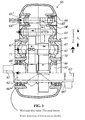
- FIG. 3 shows a three stage gear unit 60 comprising a housing 61 in which four shafts 62,63,64,65 are rotatably supported by means of roller bearings.
- Shaft 62 is rotatably supported by a pair taper roller bearings 66, 66' arranged in an X configuration, or alternatively by a pair of cylindrical bearings 66", 66"' arranged also in an X configuration (as shown on alternative shaft section 62') and which can transmit axial forces in one direction in addition to radial forces.
- Shaft 63 is rotatably supported by a pair of taper roller bearings 67, 67' in an O configuration.
- the two shaft 64, 65 are each similarly supported by pairs of taper roller bearings 68,69, 68',69' arranged in an O configuration.
- each shaft could be supported by additional pairs of bearings, typically all bearings on the shaft being of the same O or X configuration.
- auxiliary bearing support may by provided by, for example, roller or spherical bearings which may be in combination with taper roller bearings.
Landscapes
- Engineering & Computer Science (AREA)
- General Engineering & Computer Science (AREA)
- Mechanical Engineering (AREA)
- Gear Transmission (AREA)
- Medicines Containing Antibodies Or Antigens For Use As Internal Diagnostic Agents (AREA)
- Transplanting Machines (AREA)
- Lock And Its Accessories (AREA)
- Liquid Developers In Electrophotography (AREA)
- General Details Of Gearings (AREA)
- Percussion Or Vibration Massage (AREA)
- Telephone Function (AREA)
- Vehicle Body Suspensions (AREA)
Claims (7)
- Unité d'engrenage (10) comprenant un carter (11), deux arbres (12, 13) montés parallèlement l'un à l'autre, chacun supportant une roue dentée découpée en hélice (14, 15), et deux paires de paliers (17, 17', 18, 18') supportées par le carter (11) ou par rapport audit carter (11) dans un arrangement dans lequel chaque paire de paliers (17, 17', 18, 18') supporte en rotation un arbre (12, 13), les roues dentées (14, 15) des deux arbres (12, 13) étant rotatives l'une par rapport à l'autre en engrènement réciproque, deux paliers (17, 18) des deux arbres (12, 13) montés sur un côté commun des engrenages hélicoïdaux (14, 15) engrenés l'un dans l'autre étant supportés par une section de paroi essentiellement commune (21) du carter (11) de l'unité d'engrenage, un desdits deux paliers (18) étant arrangé pour transmettre à ladite section de paroi de carter des forces axiales (32) s'exerçant dans une direction allant des engrenages (14, 15) au palier, les paliers (18, 18') d'un arbre (12) étant arrangé à la manière d'une configuration de palier de type X, caractérisé en ce que l'autre palier (17) est arrangé pour transmettre, à ladite section de paroi (21) des forces axiales (31) s'exerçant dans une direction allant dudit autre palier (17) aux engrenages (14, 15) et les paliers (17, 17') de l'autre arbre (13) sont arrangés dans une configuration de type O.
- Unité d'engrenage selon la revendication 1, dans laquelle lesdits deux paliers (17, 18) des deux arbres (12, 13) montés sur un côté commun des engrenages hélicoïdaux (14, 15) engrenés l'un dans l'autre sont des roulements à rouleaux coniques.
- Unité d'engrenage (10) comprenant un carter (11), deux arbres (12, 13) montés parallèlement l'un à l'autre et supportant chacun une roue dentée découpée en hélice (14, 15), et deux paires de roulements à rouleaux coniques (17, 17', 18, 18') supportées par le carter (11) ou par rapport audit carter (11) dans un arrangement dans lequel chaque paire de paliers (17, 17', 18, 18') supporte en rotation un arbre (12, 13), les roues dentées (14, 15) des deux arbres (12, 13) étant rotatives l'une par rapport à l'autre en engrènement réciproque et les roulements à rouleaux coniques (18, 18') de l'autre arbre (12) étant prévus en écartement axial dans une configuration de type X dans laquelle le diamètre des galets de roulement de chaque palier diminue de manière progressive dans la direction qui s'écarte de l'autre palier de la paire, caractérisé en ce que la paire de roulements à rouleaux coniques (17, 17') d'un arbre (13) est prévue en écartement axial dans une configuration de type O dans laquelle le diamètre des galets de roulement de chaque palier augmente de manière progressive dans la direction qui s'écarte de l'autre palier de la paire.
- Unité d'engrenage (10) selon l'une quelconque des revendications précédentes, dans lequel chaque arbre (12, 13) comprend un engrenage hélicoïdal (14, 15) disposé en position axiale entre la paire de paliers (17, 17', 18, 18') de chaque arbre (12, 13).
- Unité d'engrenage (60) selon l'une quelconque des revendications précédentes et comprenant au moins trois arbres réciproquement parallèles (62-65), chacun étant muni d'une roue dentée découpée en hélice et étant supporté en rotation dans un carter (61) par une paire de paliers (66-69 et 66'-69'), l'arbre lent (62) étant supporté en rotation par des paliers (66, 66') arrangés en une configuration de type X ou de type O, à savoir un type de configuration opposé à celui de la configuration des paliers (67, 67') de l'arbre voisin (63).
- Unité d'engrenage (60) selon la revendication 5, dans laquelle l'arbre lent (62) est supporté en rotation par des paliers (66, 66') arrangés en une configuration de type X ou de type O, et l'unité d'engrenage (60) comprend au moins deux arbres supplémentaires (63-65), chacun étant supporté en rotation par des paliers (67-69 et 67'-69') arrangés dans la même configuration l'un par rapport à l'autre et dans une configuration opposée à celle de l'arbre lent (62).
- Unité d'engrenage (60) selon la revendication 6, dans laquelle l'arbre lent (62) est supporté en rotation par des paliers (66, 66') arrangés en une configuration de type X.
Applications Claiming Priority (3)
| Application Number | Priority Date | Filing Date | Title |
|---|---|---|---|
| GB0205569 | 2002-03-09 | ||
| GB0205569A GB2387422B (en) | 2002-03-09 | 2002-03-09 | Gear unit |
| PCT/IB2003/000791 WO2003076833A1 (fr) | 2002-03-09 | 2003-03-04 | Unite d'engrenage |
Publications (2)
| Publication Number | Publication Date |
|---|---|
| EP1485638A1 EP1485638A1 (fr) | 2004-12-15 |
| EP1485638B1 true EP1485638B1 (fr) | 2006-04-12 |
Family
ID=9932640
Family Applications (1)
| Application Number | Title | Priority Date | Filing Date |
|---|---|---|---|
| EP03704880A Expired - Lifetime EP1485638B1 (fr) | 2002-03-09 | 2003-03-04 | Unite d'engrenage |
Country Status (9)
| Country | Link |
|---|---|
| US (1) | US7472619B2 (fr) |
| EP (1) | EP1485638B1 (fr) |
| AT (1) | ATE323249T1 (fr) |
| AU (1) | AU2003207880A1 (fr) |
| DE (1) | DE60304566T2 (fr) |
| DK (1) | DK1485638T3 (fr) |
| ES (1) | ES2262975T3 (fr) |
| GB (1) | GB2387422B (fr) |
| WO (1) | WO2003076833A1 (fr) |
Families Citing this family (4)
| Publication number | Priority date | Publication date | Assignee | Title |
|---|---|---|---|---|
| US8008798B2 (en) * | 2009-12-23 | 2011-08-30 | General Electric Company | Wind turbine drivetrain system |
| US20110143880A1 (en) * | 2010-12-01 | 2011-06-16 | General Electric Company | Drivetrain for generator in wind turbine |
| EP2725261B1 (fr) * | 2011-06-24 | 2016-08-24 | Mitsubishi Electric Corporation | Dispositif d'engrenages de réduction |
| SE1250367A1 (sv) * | 2012-04-12 | 2013-10-13 | Autoinvent Transip Ab | Mobil fordonsväxelenhet |
Family Cites Families (12)
| Publication number | Priority date | Publication date | Assignee | Title |
|---|---|---|---|---|
| US3648533A (en) * | 1969-03-29 | 1972-03-14 | Siai Marchetti Spa | Torquemeter reduction gear |
| US3894621A (en) * | 1973-12-26 | 1975-07-15 | Allis Chalmers | Splined thrust washer |
| US4025136A (en) * | 1975-11-03 | 1977-05-24 | Allis-Chalmers Corporation | Multiple bearing adjusting device |
| US4297906A (en) * | 1977-09-29 | 1981-11-03 | Kenneth Costello | Gear box |
| US4890504A (en) * | 1986-07-30 | 1990-01-02 | Emerson Electric Co. | Helical gearsets |
| US5018402A (en) * | 1989-04-17 | 1991-05-28 | Beloit Corporation | Planetary gear drive for controlled defection rolls |
| US5096034A (en) * | 1991-03-15 | 1992-03-17 | Rotary Specialties | Reversing clutch mechanism |
| JPH0821489A (ja) * | 1994-07-08 | 1996-01-23 | Fanuc Ltd | 歯車装置 |
| JP4057327B2 (ja) * | 2002-03-29 | 2008-03-05 | いすゞ自動車株式会社 | 転がり軸受の給油装置 |
| US6918851B2 (en) * | 2002-11-06 | 2005-07-19 | Dana Corporation | Concentric shift system for engaging an interaxle differential lock |
| KR100598874B1 (ko) * | 2003-11-17 | 2006-07-10 | 현대자동차주식회사 | 자동변속기 |
| CN101040125A (zh) * | 2004-08-11 | 2007-09-19 | 铁姆肯公司 | 用于轮轴差速器小齿轮轴的轴承组件 |
-
2002
- 2002-03-09 GB GB0205569A patent/GB2387422B/en not_active Expired - Fee Related
-
2003
- 2003-03-04 DK DK03704880T patent/DK1485638T3/da active
- 2003-03-04 DE DE60304566T patent/DE60304566T2/de not_active Expired - Lifetime
- 2003-03-04 ES ES03704880T patent/ES2262975T3/es not_active Expired - Lifetime
- 2003-03-04 WO PCT/IB2003/000791 patent/WO2003076833A1/fr not_active Ceased
- 2003-03-04 EP EP03704880A patent/EP1485638B1/fr not_active Expired - Lifetime
- 2003-03-04 AU AU2003207880A patent/AU2003207880A1/en not_active Abandoned
- 2003-03-04 US US10/506,986 patent/US7472619B2/en not_active Expired - Fee Related
- 2003-03-04 AT AT03704880T patent/ATE323249T1/de not_active IP Right Cessation
Also Published As
| Publication number | Publication date |
|---|---|
| EP1485638A1 (fr) | 2004-12-15 |
| US20050172743A1 (en) | 2005-08-11 |
| US7472619B2 (en) | 2009-01-06 |
| GB2387422B (en) | 2004-08-18 |
| ES2262975T3 (es) | 2006-12-01 |
| ATE323249T1 (de) | 2006-04-15 |
| DE60304566T2 (de) | 2007-05-16 |
| GB0205569D0 (en) | 2002-04-24 |
| DK1485638T3 (da) | 2006-08-07 |
| AU2003207880A1 (en) | 2003-09-22 |
| GB2387422A (en) | 2003-10-15 |
| WO2003076833A1 (fr) | 2003-09-18 |
| DE60304566D1 (de) | 2006-05-24 |
Similar Documents
| Publication | Publication Date | Title |
|---|---|---|
| JP4289353B2 (ja) | 遊星式差動ねじ型回転−直線運動変換装置 | |
| US11365784B2 (en) | Eccentric oscillation type speed reducer | |
| US8758190B2 (en) | Gear assembly with asymmetric flex pin | |
| JP5156961B2 (ja) | 減速装置 | |
| US5588328A (en) | Gear mechanism improved to remove backlash | |
| EP0488161B1 (fr) | Réducteur planétaire | |
| JP4594296B2 (ja) | マルチシャフト押出し機を駆動するためのギア装置 | |
| EP0196650B1 (fr) | Ensemble de transmission | |
| EP3690281B1 (fr) | Dispositif d'engrenage à ondes de type unitaire | |
| EP1630456B1 (fr) | Vis a billes, et direction assistee electrique comprenant cette vis | |
| US20070232433A1 (en) | Oscillating internally meshing planetary gear reducer | |
| EP1485638B1 (fr) | Unite d'engrenage | |
| JP2003528263A (ja) | 遊星変速機において動力を分担する歯車装置 | |
| EP1239191B1 (fr) | Unité de différentiel | |
| WO2018159539A1 (fr) | Mécanisme de came d'engrenage à rouleaux | |
| CN110735887B (zh) | 无反向间隙的行星齿轮机构及行星减速机 | |
| EP3572692A1 (fr) | Engrenage réducteur à vitesse commutable | |
| KR20030078685A (ko) | 차량의 스티어링 장치 | |
| EP2821658B1 (fr) | Boîte de vitesse | |
| EP1840414B1 (fr) | Dispositif d'engrenage et appareil à direction assistée électrique | |
| CN114370487A (zh) | 谐波减速器及传动装置 | |
| JP3937556B2 (ja) | 複列円すいころ軸受装置 | |
| JP4745535B2 (ja) | トルクコンバータ | |
| JP2025099734A (ja) | 減速装置 | |
| EP0866927B1 (fr) | Transmission par engrenage |
Legal Events
| Date | Code | Title | Description |
|---|---|---|---|
| PUAI | Public reference made under article 153(3) epc to a published international application that has entered the european phase |
Free format text: ORIGINAL CODE: 0009012 |
|
| 17P | Request for examination filed |
Effective date: 20041011 |
|
| AK | Designated contracting states |
Kind code of ref document: A1 Designated state(s): AT BE BG CH CY CZ DE DK EE ES FI FR GB GR HU IE IT LI LU MC NL PT RO SE SI SK TR |
|
| AX | Request for extension of the european patent |
Extension state: AL LT LV MK RO |
|
| 17Q | First examination report despatched |
Effective date: 20041208 |
|
| GRAP | Despatch of communication of intention to grant a patent |
Free format text: ORIGINAL CODE: EPIDOSNIGR1 |
|
| GRAS | Grant fee paid |
Free format text: ORIGINAL CODE: EPIDOSNIGR3 |
|
| GRAA | (expected) grant |
Free format text: ORIGINAL CODE: 0009210 |
|
| RAP1 | Party data changed (applicant data changed or rights of an application transferred) |
Owner name: HANSEN TRANSMISSIONS INTERNATIONAL NV |
|
| AK | Designated contracting states |
Kind code of ref document: B1 Designated state(s): AT BE BG CH CY CZ DE DK EE ES FI FR GB GR HU IE IT LI LU MC NL PT RO SE SI SK TR |
|
| PG25 | Lapsed in a contracting state [announced via postgrant information from national office to epo] |
Ref country code: IT Free format text: LAPSE BECAUSE OF FAILURE TO SUBMIT A TRANSLATION OF THE DESCRIPTION OR TO PAY THE FEE WITHIN THE PRESCRIBED TIME-LIMIT;WARNING: LAPSES OF ITALIAN PATENTS WITH EFFECTIVE DATE BEFORE 2007 MAY HAVE OCCURRED AT ANY TIME BEFORE 2007. THE CORRECT EFFECTIVE DATE MAY BE DIFFERENT FROM THE ONE RECORDED. Effective date: 20060412 Ref country code: CH Free format text: LAPSE BECAUSE OF FAILURE TO SUBMIT A TRANSLATION OF THE DESCRIPTION OR TO PAY THE FEE WITHIN THE PRESCRIBED TIME-LIMIT Effective date: 20060412 Ref country code: SK Free format text: LAPSE BECAUSE OF FAILURE TO SUBMIT A TRANSLATION OF THE DESCRIPTION OR TO PAY THE FEE WITHIN THE PRESCRIBED TIME-LIMIT Effective date: 20060412 Ref country code: CZ Free format text: LAPSE BECAUSE OF FAILURE TO SUBMIT A TRANSLATION OF THE DESCRIPTION OR TO PAY THE FEE WITHIN THE PRESCRIBED TIME-LIMIT Effective date: 20060412 Ref country code: SI Free format text: LAPSE BECAUSE OF FAILURE TO SUBMIT A TRANSLATION OF THE DESCRIPTION OR TO PAY THE FEE WITHIN THE PRESCRIBED TIME-LIMIT Effective date: 20060412 Ref country code: AT Free format text: LAPSE BECAUSE OF FAILURE TO SUBMIT A TRANSLATION OF THE DESCRIPTION OR TO PAY THE FEE WITHIN THE PRESCRIBED TIME-LIMIT Effective date: 20060412 Ref country code: LI Free format text: LAPSE BECAUSE OF FAILURE TO SUBMIT A TRANSLATION OF THE DESCRIPTION OR TO PAY THE FEE WITHIN THE PRESCRIBED TIME-LIMIT Effective date: 20060412 Ref country code: NL Free format text: LAPSE BECAUSE OF FAILURE TO SUBMIT A TRANSLATION OF THE DESCRIPTION OR TO PAY THE FEE WITHIN THE PRESCRIBED TIME-LIMIT Effective date: 20060412 Ref country code: RO Free format text: LAPSE BECAUSE OF FAILURE TO SUBMIT A TRANSLATION OF THE DESCRIPTION OR TO PAY THE FEE WITHIN THE PRESCRIBED TIME-LIMIT Effective date: 20060412 |
|
| REG | Reference to a national code |
Ref country code: GB Ref legal event code: FG4D |
|
| REG | Reference to a national code |
Ref country code: CH Ref legal event code: EP |
|
| REF | Corresponds to: |
Ref document number: 60304566 Country of ref document: DE Date of ref document: 20060524 Kind code of ref document: P |
|
| REG | Reference to a national code |
Ref country code: IE Ref legal event code: FG4D |
|
| PG25 | Lapsed in a contracting state [announced via postgrant information from national office to epo] |
Ref country code: SE Free format text: LAPSE BECAUSE OF FAILURE TO SUBMIT A TRANSLATION OF THE DESCRIPTION OR TO PAY THE FEE WITHIN THE PRESCRIBED TIME-LIMIT Effective date: 20060712 |
|
| REG | Reference to a national code |
Ref country code: DK Ref legal event code: T3 |
|
| PG25 | Lapsed in a contracting state [announced via postgrant information from national office to epo] |
Ref country code: PT Free format text: LAPSE BECAUSE OF FAILURE TO SUBMIT A TRANSLATION OF THE DESCRIPTION OR TO PAY THE FEE WITHIN THE PRESCRIBED TIME-LIMIT Effective date: 20060912 |
|
| NLV1 | Nl: lapsed or annulled due to failure to fulfill the requirements of art. 29p and 29m of the patents act | ||
| REG | Reference to a national code |
Ref country code: CH Ref legal event code: PL |
|
| REG | Reference to a national code |
Ref country code: ES Ref legal event code: FG2A Ref document number: 2262975 Country of ref document: ES Kind code of ref document: T3 |
|
| PLBE | No opposition filed within time limit |
Free format text: ORIGINAL CODE: 0009261 |
|
| STAA | Information on the status of an ep patent application or granted ep patent |
Free format text: STATUS: NO OPPOSITION FILED WITHIN TIME LIMIT |
|
| 26N | No opposition filed |
Effective date: 20070115 |
|
| EN | Fr: translation not filed | ||
| PG25 | Lapsed in a contracting state [announced via postgrant information from national office to epo] |
Ref country code: MC Free format text: LAPSE BECAUSE OF NON-PAYMENT OF DUE FEES Effective date: 20070331 Ref country code: IE Free format text: LAPSE BECAUSE OF NON-PAYMENT OF DUE FEES Effective date: 20070305 |
|
| PG25 | Lapsed in a contracting state [announced via postgrant information from national office to epo] |
Ref country code: GR Free format text: LAPSE BECAUSE OF FAILURE TO SUBMIT A TRANSLATION OF THE DESCRIPTION OR TO PAY THE FEE WITHIN THE PRESCRIBED TIME-LIMIT Effective date: 20060713 Ref country code: FR Free format text: LAPSE BECAUSE OF FAILURE TO SUBMIT A TRANSLATION OF THE DESCRIPTION OR TO PAY THE FEE WITHIN THE PRESCRIBED TIME-LIMIT Effective date: 20070309 |
|
| PG25 | Lapsed in a contracting state [announced via postgrant information from national office to epo] |
Ref country code: BG Free format text: LAPSE BECAUSE OF FAILURE TO SUBMIT A TRANSLATION OF THE DESCRIPTION OR TO PAY THE FEE WITHIN THE PRESCRIBED TIME-LIMIT Effective date: 20060712 |
|
| PG25 | Lapsed in a contracting state [announced via postgrant information from national office to epo] |
Ref country code: EE Free format text: LAPSE BECAUSE OF FAILURE TO SUBMIT A TRANSLATION OF THE DESCRIPTION OR TO PAY THE FEE WITHIN THE PRESCRIBED TIME-LIMIT Effective date: 20060412 |
|
| PG25 | Lapsed in a contracting state [announced via postgrant information from national office to epo] |
Ref country code: FR Free format text: LAPSE BECAUSE OF FAILURE TO SUBMIT A TRANSLATION OF THE DESCRIPTION OR TO PAY THE FEE WITHIN THE PRESCRIBED TIME-LIMIT Effective date: 20060412 |
|
| PG25 | Lapsed in a contracting state [announced via postgrant information from national office to epo] |
Ref country code: CY Free format text: LAPSE BECAUSE OF FAILURE TO SUBMIT A TRANSLATION OF THE DESCRIPTION OR TO PAY THE FEE WITHIN THE PRESCRIBED TIME-LIMIT Effective date: 20060412 Ref country code: LU Free format text: LAPSE BECAUSE OF NON-PAYMENT OF DUE FEES Effective date: 20070304 |
|
| PG25 | Lapsed in a contracting state [announced via postgrant information from national office to epo] |
Ref country code: TR Free format text: LAPSE BECAUSE OF FAILURE TO SUBMIT A TRANSLATION OF THE DESCRIPTION OR TO PAY THE FEE WITHIN THE PRESCRIBED TIME-LIMIT Effective date: 20060412 Ref country code: HU Free format text: LAPSE BECAUSE OF FAILURE TO SUBMIT A TRANSLATION OF THE DESCRIPTION OR TO PAY THE FEE WITHIN THE PRESCRIBED TIME-LIMIT Effective date: 20061013 |
|
| REG | Reference to a national code |
Ref country code: GB Ref legal event code: 732E Free format text: REGISTERED BETWEEN 20110224 AND 20110302 |
|
| PG25 | Lapsed in a contracting state [announced via postgrant information from national office to epo] |
Ref country code: IT Free format text: LAPSE BECAUSE OF NON-PAYMENT OF DUE FEES Effective date: 20100304 |
|
| PGFP | Annual fee paid to national office [announced via postgrant information from national office to epo] |
Ref country code: DK Payment date: 20110218 Year of fee payment: 9 |
|
| PGFP | Annual fee paid to national office [announced via postgrant information from national office to epo] |
Ref country code: FI Payment date: 20110221 Year of fee payment: 9 |
|
| REG | Reference to a national code |
Ref country code: DE Ref legal event code: R081 Ref document number: 60304566 Country of ref document: DE Owner name: HANSEN INDUSTRIAL TRANSMISSIONS N.V., BE Free format text: FORMER OWNER: HANSEN TRANSMISSIONS INTERNATIONAL N.V., EDEGEM, BE Effective date: 20110513 |
|
| PGFP | Annual fee paid to national office [announced via postgrant information from national office to epo] |
Ref country code: IT Payment date: 20110222 Year of fee payment: 9 Ref country code: GB Payment date: 20110224 Year of fee payment: 9 Ref country code: BE Payment date: 20110222 Year of fee payment: 9 Ref country code: ES Payment date: 20110309 Year of fee payment: 9 Ref country code: DE Payment date: 20110308 Year of fee payment: 9 |
|
| PGRI | Patent reinstated in contracting state [announced from national office to epo] |
Ref country code: IT Effective date: 20110616 |
|
| REG | Reference to a national code |
Ref country code: ES Ref legal event code: PC2A Owner name: HANSEN INDUSTRIAL TRANSMISSIONS, N.V. Effective date: 20110908 |
|
| BERE | Be: lapsed |
Owner name: HANSEN INDUSTRIAL TRANSMISSIONS N.V. Effective date: 20120331 |
|
| PG25 | Lapsed in a contracting state [announced via postgrant information from national office to epo] |
Ref country code: FI Free format text: LAPSE BECAUSE OF NON-PAYMENT OF DUE FEES Effective date: 20120304 |
|
| REG | Reference to a national code |
Ref country code: DK Ref legal event code: EBP |
|
| GBPC | Gb: european patent ceased through non-payment of renewal fee |
Effective date: 20120304 |
|
| PG25 | Lapsed in a contracting state [announced via postgrant information from national office to epo] |
Ref country code: BE Free format text: LAPSE BECAUSE OF NON-PAYMENT OF DUE FEES Effective date: 20120331 Ref country code: GB Free format text: LAPSE BECAUSE OF NON-PAYMENT OF DUE FEES Effective date: 20120304 |
|
| REG | Reference to a national code |
Ref country code: DE Ref legal event code: R119 Ref document number: 60304566 Country of ref document: DE Effective date: 20121002 |
|
| PG25 | Lapsed in a contracting state [announced via postgrant information from national office to epo] |
Ref country code: IT Free format text: LAPSE BECAUSE OF NON-PAYMENT OF DUE FEES Effective date: 20120304 |
|
| PG25 | Lapsed in a contracting state [announced via postgrant information from national office to epo] |
Ref country code: DK Free format text: LAPSE BECAUSE OF NON-PAYMENT OF DUE FEES Effective date: 20120331 |
|
| REG | Reference to a national code |
Ref country code: ES Ref legal event code: FD2A Effective date: 20130710 |
|
| PG25 | Lapsed in a contracting state [announced via postgrant information from national office to epo] |
Ref country code: ES Free format text: LAPSE BECAUSE OF NON-PAYMENT OF DUE FEES Effective date: 20120305 |
|
| PG25 | Lapsed in a contracting state [announced via postgrant information from national office to epo] |
Ref country code: DE Free format text: LAPSE BECAUSE OF NON-PAYMENT OF DUE FEES Effective date: 20121002 |