EP1485683B1 - Antenne a cornet remplie d'un dielectrique et comprenant un element d'etancheite - Google Patents
Antenne a cornet remplie d'un dielectrique et comprenant un element d'etancheite Download PDFInfo
- Publication number
- EP1485683B1 EP1485683B1 EP03708803A EP03708803A EP1485683B1 EP 1485683 B1 EP1485683 B1 EP 1485683B1 EP 03708803 A EP03708803 A EP 03708803A EP 03708803 A EP03708803 A EP 03708803A EP 1485683 B1 EP1485683 B1 EP 1485683B1
- Authority
- EP
- European Patent Office
- Prior art keywords
- aperture
- dielectric body
- housing
- wave guide
- horn antenna
- Prior art date
- Legal status (The legal status is an assumption and is not a legal conclusion. Google has not performed a legal analysis and makes no representation as to the accuracy of the status listed.)
- Expired - Lifetime
Links
- 238000007789 sealing Methods 0.000 title claims abstract description 25
- 239000000463 material Substances 0.000 claims description 26
- 238000000034 method Methods 0.000 claims description 23
- 229920002313 fluoropolymer Polymers 0.000 claims description 11
- 230000005540 biological transmission Effects 0.000 claims description 4
- 238000012937 correction Methods 0.000 claims description 3
- 238000006073 displacement reaction Methods 0.000 claims description 2
- 238000007493 shaping process Methods 0.000 claims 1
- 238000004519 manufacturing process Methods 0.000 abstract 1
- 239000000126 substance Substances 0.000 description 10
- 238000009833 condensation Methods 0.000 description 6
- 230000005494 condensation Effects 0.000 description 6
- 230000008878 coupling Effects 0.000 description 5
- 238000010168 coupling process Methods 0.000 description 5
- 238000005859 coupling reaction Methods 0.000 description 5
- 238000013461 design Methods 0.000 description 3
- 238000004891 communication Methods 0.000 description 2
- 230000000295 complement effect Effects 0.000 description 2
- 238000011156 evaluation Methods 0.000 description 2
- 239000012535 impurity Substances 0.000 description 2
- 238000009825 accumulation Methods 0.000 description 1
- 230000006978 adaptation Effects 0.000 description 1
- 230000002925 chemical effect Effects 0.000 description 1
- 238000011109 contamination Methods 0.000 description 1
- 238000005260 corrosion Methods 0.000 description 1
- 230000007797 corrosion Effects 0.000 description 1
- 230000000694 effects Effects 0.000 description 1
- 230000007613 environmental effect Effects 0.000 description 1
- 230000001747 exhibiting effect Effects 0.000 description 1
- 238000004880 explosion Methods 0.000 description 1
- 239000012530 fluid Substances 0.000 description 1
- 238000009434 installation Methods 0.000 description 1
- 239000007788 liquid Substances 0.000 description 1
- 238000012423 maintenance Methods 0.000 description 1
- 238000005259 measurement Methods 0.000 description 1
- 239000002184 metal Substances 0.000 description 1
- 239000011236 particulate material Substances 0.000 description 1
- 239000007787 solid Substances 0.000 description 1
- XLYOFNOQVPJJNP-UHFFFAOYSA-N water Substances O XLYOFNOQVPJJNP-UHFFFAOYSA-N 0.000 description 1
Images

Classifications
-
- H—ELECTRICITY
- H01—ELECTRIC ELEMENTS
- H01Q—ANTENNAS, i.e. RADIO AERIALS
- H01Q1/00—Details of, or arrangements associated with, antennas
- H01Q1/12—Supports; Mounting means
- H01Q1/22—Supports; Mounting means by structural association with other equipment or articles
- H01Q1/225—Supports; Mounting means by structural association with other equipment or articles used in level-measurement devices, e.g. for level gauge measurement
-
- G—PHYSICS
- G01—MEASURING; TESTING
- G01F—MEASURING VOLUME, VOLUME FLOW, MASS FLOW OR LIQUID LEVEL; METERING BY VOLUME
- G01F23/00—Indicating or measuring liquid level or level of fluent solid material, e.g. indicating in terms of volume or indicating by means of an alarm
- G01F23/22—Indicating or measuring liquid level or level of fluent solid material, e.g. indicating in terms of volume or indicating by means of an alarm by measuring physical variables, other than linear dimensions, pressure or weight, dependent on the level to be measured, e.g. by difference of heat transfer of steam or water
- G01F23/28—Indicating or measuring liquid level or level of fluent solid material, e.g. indicating in terms of volume or indicating by means of an alarm by measuring physical variables, other than linear dimensions, pressure or weight, dependent on the level to be measured, e.g. by difference of heat transfer of steam or water by measuring the variations of parameters of electromagnetic or acoustic waves applied directly to the liquid or fluent solid material
- G01F23/284—Electromagnetic waves
-
- H—ELECTRICITY
- H01—ELECTRIC ELEMENTS
- H01Q—ANTENNAS, i.e. RADIO AERIALS
- H01Q13/00—Waveguide horns or mouths; Slot antennas; Leaky-waveguide antennas; Equivalent structures causing radiation along the transmission path of a guided wave
- H01Q13/02—Waveguide horns
-
- H—ELECTRICITY
- H01—ELECTRIC ELEMENTS
- H01Q—ANTENNAS, i.e. RADIO AERIALS
- H01Q19/00—Combinations of primary active antenna elements and units with secondary devices, e.g. with quasi-optical devices, for giving the antenna a desired directional characteristic
- H01Q19/06—Combinations of primary active antenna elements and units with secondary devices, e.g. with quasi-optical devices, for giving the antenna a desired directional characteristic using refracting or diffracting devices, e.g. lens
- H01Q19/08—Combinations of primary active antenna elements and units with secondary devices, e.g. with quasi-optical devices, for giving the antenna a desired directional characteristic using refracting or diffracting devices, e.g. lens for modifying the radiation pattern of a radiating horn in which it is located
-
- H—ELECTRICITY
- H01—ELECTRIC ELEMENTS
- H01Q—ANTENNAS, i.e. RADIO AERIALS
- H01Q19/00—Combinations of primary active antenna elements and units with secondary devices, e.g. with quasi-optical devices, for giving the antenna a desired directional characteristic
- H01Q19/06—Combinations of primary active antenna elements and units with secondary devices, e.g. with quasi-optical devices, for giving the antenna a desired directional characteristic using refracting or diffracting devices, e.g. lens
- H01Q19/09—Combinations of primary active antenna elements and units with secondary devices, e.g. with quasi-optical devices, for giving the antenna a desired directional characteristic using refracting or diffracting devices, e.g. lens wherein the primary active element is coated with or embedded in a dielectric or magnetic material
Definitions
- the present invention relates to a horn antenna for use with a level gauge utilizing a radar for determination of a surface level of a medium stored in a tank, whereby the invention discloses both a device and a method for achieving a horn antenna which is mechanically constituted such that the horn antenna will withstand the environment inside the tank in the form of pressure variations and contaminating substances in order to prevent contamination of the antenna and leakage to the outside of the tank.
- Horn antennas are used extensively in connection with radar based level gauging. In the design of horn antennas, one tries to obtain as high an antenna gain as possible at the same time as one desires a low level of side lobes. Furthermore, the antenna must withstand strain brought on by the tank environment, such as occurrence of high or low pressure, high or low temperatures, condensation and aggressive substances. These types of strains may occur individually or in combination with each other.
- a horn of an antenna lacking a process window has a seal against the tank atmosphere in the shape of a dielectric rod which is pointed at the end facing the tank and which is placed at the neck of the horn, i.e. at the narrowest section of the horn. See patent document US 6 278 411 .
- the ability of the antenna to withstand pressure, having such an arrangement, is good.
- impurities and condensation difficulties with dampening and reflection of microwaves remain, as the antenna is covered with a layer of impurities or condensation. This is further accentuated when using higher frequencies than those previously normally used for radar based level gauging, as the dimensions of the horn itself are reduced. Through the smaller dimensions of the antenna horn the difficulties with condensation and soiling are increased. Condensation in the form of e.g. water, in this case leads to increased dampening.
- a horn having a process window is less sensitive to condensation and soiling but it is not able to resist pressure as well as the horn lacking a process window. This is due to the fact that the thickness of the process window is kept within as few quarter wavelengths as possible. Using such a high microwave frequency as 24 GHz a process window made from a PTFE-plastic material will have a thickness of 4 mm. A plastic layer of that thickness will be fairly sensitive for the effects of pressure.
- the materials used for process windows are preferably different kinds of fluoroplastic materials, as these exhibit good resistance to chemicals. On the other hand the mechanical properties are not the best.
- the antenna and its related feeding arrangement In microwave based gauging of a level of a surface of a medium in a tank, the antenna and its related feeding arrangement generally constitute a feed-through in a wall (top, side, or bottom) of the tank.
- the portion of the feed-through that is located outside the tank may or may not be in direct communication with the atmosphere outside the tank.
- the feed-through may be in direct communication with the outside atmosphere.
- it may be connected to a compartment that houses electronics, which should be kept separated from the atmosphere in the tank.
- the atmosphere in the tank may contain substances that could cause corrosion, explosion, health risks, and environmental damage.
- the risk of leakage between the inside and the outside of the tank may be an important factor to take into account when designing the antenna and related parts.
- the patent application DE 100 40 943 A1 relates to a horn antenna. That document discloses a horn antenna wherein a dielectric filling material is used for filling essentially all of the interior of the horn antenna in order to avoid deposits of condensed substances or dirt in the particularly critical area of the antenna. Thereby, there is essentially no room for deposits in the interior of the antenna. This seems to provide a solution to the problem of preventing disturbances of the measurement signal in the antenna. However, the document does not address the problem of preventing leakage from the tank through the antenna to the outside of the tank.
- the document further discloses two different wave guide feeding arrangements for the horn antenna. In one arrangement, the wave guide is completely filled by a dielectric. In another arrangement, the wave guide is partly air filled. In conclusion, there is no description in relation to any of these arrangements of whether or not the wave guide is provided sealing means to prevent the type of leakage mentioned above.
- Documents JP 54-083740 and JP 2002-009542 both relate to horn antenna provided with dielectric "windows" to protect the interior of the antenna.
- the windows are sealed against the interior of the antenna by a sealing element arranged between the window and the horn antenna.
- a horn antenna at a radar level gauge for determination of a surface level of a medium stored in a tank.
- the antenna is intended for transmission and reception of microwaves using a microwave unit arranged at the roof of the tank.
- the antenna comprises a first conductive housing with a wave guide port which is connectable to a wave guide, a first aperture which is separate from the wave guide port and a first divergent section between said wave guide port and the first aperture.
- a dielectric body is arranged within and essentially fitting the first conductive housing, which body has a free end in the area of the first aperture.
- the horn antenna is characterized in that a locking device is arranged around the first aperture, which locking device is arranged to affix the dielectric body inside the first housing and that in the area of the locking device is arranged at least one flexible sealing element between the dielectric body and the first housing.
- the invention thereby provides a device for efficiently separating the atmospheres inside and outside the tank while maintaining a mechanically pressure resistant antenna design and an efficient microwave performance.
- a method for achieving a horn antenna which is mechanically constituted such that the horn antenna will withstand the environment present inside the tank in the form of pressure variations and contaminating substances.
- the method comprises making a first divergent conductive housing with a wave guide port which is attachable to a wave guide, a first aperture which is separate from the wave guide port and a divergent section between the wave guide port and the first aperture.
- a dielectric body is affixed inside and essentially filling the first housing such that a first end of the dielectric body appears in the area of the first aperture.
- a locking device is arranged around the first aperture, whereby the dielectric body is fixed in the first housing.
- a flexible sealing element is arranged between the dielectric body and the first housing in the area of the locking device.
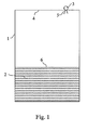
- a tank 1 is used for storing a medium 2.
- the medium can be a fluid, such as oil, refined products and gas in the liquid state, or a particulate material, i.e. a pulverized solid state substance.
- a radar 3 is arranged at the roof 4 of the tank 1, wherefrom a microwave beam is transmitted from the radar via an antenna 5 at the inside of the tank. The emitted beam is reflected from the surface 6 of the medium and received by the antenna 5.
- a determination of the surface 6 level of the medium can be made using known procedures.
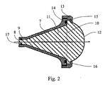
- FIG. 2 shows a first embodiment of the horn antenna in accordance with the present invention.
- the antenna displays a first conductive housing 7, preferably of metal.
- the housing 7 has a wave guide port 8 which is attachable to a wave guide. In the area of the wave guide port 8 the housing 7 may be equipped with a section 9 of constant cross-section which constitutes an extension of the wave guide.
- the antenna housing 7 displays a first aperture 10, which in the embodiment according to figure 2 is concentric with the wave guide port 8 and positioned axially spaced from the wave guide port 8 and a first divergent section between the wave guide port and the first aperture.
- a dielectric body 11 is arranged within and essentially filling the first conductive housing 7 and exhibits a free end 12 in the area of the first aperture 10.
- a locking device 13 is arranged around the first aperture, which locking device is arranged to fix the dielectric body 11 in the first housing 7.
- a flexible sealing element 16 between the dielectric body and the first housing 7.
- the flexible sealing element 16 is suitably constituted of one or several O-rings.
- the locking can, as is shown in figure 2 , be achieved through the first housing 7 exhibiting a radially outwards directed flange 14 around the first aperture 10 against which a complementary designed flange 15, at the free end 12 of the dielectric body is pressed by a ring 13, intended as locking device, which ring e.g.
- the flexible sealing element 16 in this embodiment is suitably placed between the flange 14 of the housing and the flange 15 of the dielectric body.
- the sealing element 16, between the dielectric body 11 and the first housing 7 according to figure 2 is arranged to receive pressure between the dielectric body 11 and the first housing 7, such that it is arranged to be pressurized further upon displacement of the dielectric body 11 relative to the first housing 7 caused by the pressure present in the tank.
- the sealing element 15 is preferably made of a material, e.g. a fluoroplastic material, which is resistant to chemical effects from the kind of mediums which are supposed to be stored in the tank where the antenna is supposed to be used.
- a further sealing element 17 may be arranged between the dielectric body 11 and the housing 7 in the area of the wave guide port 8. Also this sealing element 17 preferably consist of one or several O-rings.
- the free end 12 of the dielectric body is shaped as a lens, e.g. an essentially concave lens, as is shown in figure 2 .
- a possibly occurring phase error of the microwaves can be reduced, taking advantage of the propagation speed of the micro waves in the lens material, and transmission from the antenna of an essentially plane wave front can be achieved.
- the dielectric body 11 is suitably made from two different materials with a surface interface to each other, where the outermost layer of the free end of the body preferably is made from a fluoroplastic material having good resistance to chemicals while the rest of the body is made from a plastic material having, compared to the fluoroplastic material, better thermal properties but is less resistant to chemicals, such as a PPS-plastic.
- the fluoroplastic material layer suitably has a thickness corresponding to a quarter of the wavelength which the antenna is intended for, whereby the reflection from the antenna opening is reduced.
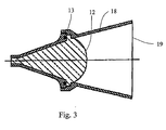
- FIG. 3 An additional embodiment, for use when the tank connection comprises a sleeve coupling as above, is shown in figure 4 .
- the antenna shown in figure 3 is essentially constituted as described with reference to figure 2 but with the addition that it, for increased antenna gain, displays a second divergent conductive housing 18.
- the second housing 18, in the embodiment according to figure 3 is concentric with the first housing 7 and extends the first housing 7 axially towards a second aperture 19, which is situated axially outside of the free end 12 of the dielectric body.
- the extension 20 can be realized cylindrical with a constant cross-section, with the purpose of extending the antenna past the extension of the coupling sleeve, such that interference from the coupling sleeve is avoided.
- a horn antenna being mechanically constituted such that the horn antenna can withstand the environment of the tank interior in the form of pressure variations and contaminating substances can be achieved through a method as follows.
- a first divergent conductive housing 7 is made and provided with a wave guide port 8, which is made attachable to a wave guide.
- the housing 7 is further provided with a first aperture 10, which is concentric with the wave guide port 8 and situated axially spaced from the wave guide port 8.
- the housing 7 is brought to connect the wave guide port 8 and the first aperture 10 through a divergent section being arranged there between.
- a dielectric body 11 is arranged inside of and essentially filling the first housing 7, such that a free end 12 of the body 11 appears in the area of the first aperture 10.
- Around the first aperture 10 is arranged a locking device 13, through which the dielectric body 11 is fixed in the first housing 7. Further is arranged, in the area of the locking device 13, at least one flexible sealing element 16 between the dielectric body 11 and the first housing 7.
- An additional sealing element 17 is suitably arranged between the dielectric body 11 and the first housing 7 in the area of the wave guide port 8.
- This sealing element 17 as well as the sealing element 16 in the area of the locking device 13, are suitably achieved through arranging one or several O-rings between the dielectric body 11 and the first housing 7.
- the free end 12 of the dielectric body is suitably shaped as a lens for correction of a possible phase error of the microwaves and achievement of an essentially plane wave front.
- the dielectric body 11 is suitably made from two different materials with a surface interface to each other, where the outermost layer of the free end of the dielectric body is made of a fluoroplastic material while the remainder of the dielectric body is made from a plastic material having better thermal properties, such as a PPS-plastic.
- the fluoroplastic material layer is hereby suitably given a thickness corresponding to a quarter of the wavelength for which the antenna is intended.
- a second conductive housing 18, 20 is suitably attached around the first aperture 10, concentrically with the first housing 7.
- the second conductive housing 20 is suitably made having a section of essentially constant cross-section between the first aperture 10 and the second aperture 19.
Landscapes
- Physics & Mathematics (AREA)
- Electromagnetism (AREA)
- Thermal Sciences (AREA)
- Fluid Mechanics (AREA)
- General Physics & Mathematics (AREA)
- Waveguide Aerials (AREA)
- Details Of Aerials (AREA)
- Aerials With Secondary Devices (AREA)
Claims (20)
- Antenne à cornet pour la transmission et la réception de micro-ondes lors du jaugeage d'un niveau d'une surface d'un milieu stocké dans un réservoir au moyen d'une unité de micro-ondes disposée sur le toit du réservoir, où l'antenne comprend :- un premier logement conducteur (7) comportant un port de guide d'ondes (8), qui peut être raccordé à un guide d'ondes, ledit premier logement conducteur (7) comportant une première ouverture (10), laquelle est séparée du port de guide d'ondes (8), une première section divergente entre le port de guide d'ondes (8) et la première ouverture (10), et un corps diélectrique (11) disposé à l'intérieur et remplissant essentiellement le premier logement conducteur (7), lequel corps (11) possède une extrémité libre (12) dans la zone de la première ouverture (10),
caractérisée en ce que- autour de la première ouverture (10) est disposé un dispositif de verrouillage (13),- le dispositif de verrouillage (13) est agencé afin de fixer le corps diélectrique (11) dans le premier logement (7), et- dans la zone du dispositif de verrouillage (13) est disposé au moins un élément d'étanchéité flexible (16) entre le corps diélectrique (11) et le premier logement (7), pour séparer les atmosphères à l'intérieur et à l'extérieur du réservoir. - Antenne à cornet selon la revendication 1, caractérisée en ce que l'élément de scellement (16) est disposé afin d'absorber une pression entre le corps diélectrique (11) et le premier logement (7), de sorte qu'il soit agencé afin d'être pressurisé en cas de déplacement du corps diélectrique (11) par rapport au premier logement (7) provoqué par une pression à l'intérieur du réservoir.
- Antenne à cornet selon la revendication 1, caractérisée en ce que dans la zone du port de guide d'ondes (8), il est disposé au moins un élément d'étanchéité (17) additionnel entre le corps diélectrique (11) et le premier logement (7).
- Antenne à cornet selon la revendication 1 ou 3, caractérisée en ce que au moins un des éléments de scellement (16,17) inclut au moins un joint torique.
- Antenne à cornet selon une quelconque des revendications 1 à 4, caractérisée en ce que l'extrémité libre (12) du corps diélectrique est façonnée comme une lentille à des fins de correction d'une erreur de phase éventuelle des micro-ondes, pour obtenir un front d'onde essentiellement plat.
- Antenne à cornet selon une quelconque des revendications 1 à 5, caractérisée en ce que le corps diélectrique (11) est composé de deux matériaux différents ayant une interface de surface l'un par rapport à l'autre.
- Antenne à cornet selon la revendication 6, caractérisée en ce que une couche la plus extérieure de l'extrémité libre du corps diélectrique est constituée d'un matériau fluoroplastique alors que le reste du corps diélectrique (11) est constitué d'un matériau plastique ayant de meilleures propriétés thermiques, comme du plastique PPS.
- Antenne à cornet selon la revendication 7, caractérisée en ce que une épaisseur du matériau fluoroplastique correspond à un quart de la longueur d'onde pour laquelle l'antenne est prévue.
- Antenne à cornet selon une quelconque des revendications 1 à 8, caractérisée en ce que, autour de la première ouverture (10), il est disposé un second logement conducteur (18, 20) qui étend le premier logement (7) dans la direction d'une seconde ouverture (19).
- Antenne à cornet selon la revendication 9, caractérisée en ce que le second logement conducteur (18) inclut une seconde portion divergente entre la première ouverture (10) et la seconde ouverture (19).
- Antenne à cornet selon la revendication 9, caractérisée en ce que le second logement conducteur (20) inclut une portion ayant une section transversale essentiellement constante entre la première ouverture (10) et la seconde ouverture (19).
- Procédé de fabrication d'une antenne à cornet pour la transmission et la réception de micro-ondes lors du jaugeage d'un niveau d'une surface d'un milieu stocké dans un réservoir au moyen d'une unité de micro-ondes disposée sur le toit du réservoir, lequel procédé comprend de : fabriquer un premier logement conducteur (7) comportant un port de guide d'ondes (8), lequel peut être raccordé à un guide d'ondes, une première ouverture (10) qui est séparée du port de guide d'ondes (8) et une section divergente entre le port de guide d'ondes (8) et la première ouverture (10) ; fixer un corps diélectrique (11) à l'intérieur dudit premier logement conducteur (7) de sorte qu'il remplisse essentiellement le premier logement (7) et de sorte que une extrémité libre (12) du corps diélectrique (11) soit située dans la zone de la première ouverture (10), agencer un dispositif de verrouillage (13) autour de la première ouverture (10), moyennant quoi le corps diélectrique (11) est fixé dans le premier logement conducteur (7) et agencer, dans la zone du dispositif de verrouillage (13), un élément d'étanchéité flexible (16) entre le corps diélectrique (11) et le premier logement (7), pour séparer les atmosphères à l'intérieur et à l'extérieur du réservoir.
- Procédé selon la revendication 12, comprenant en outre de : disposer, dans la zone du port de guide d'ondes (8), un élément d'étanchéité additionnel (17) entre le corps diélectrique (11) et le premier logement (7).
- Procédé selon la revendication 12 ou 13, comprenant en outre de : utiliser comme élément d'étanchéité (16, 17) au moins un joint torique.
- Procédé selon une quelconque des revendications 12 à 14, comprenant en outre de : façonner l'extrémité libre (12) du corps diélectrique comme une lentille à des fins de correction d'une erreur de phase éventuelle des micro-ondes pour obtenir un front d'onde essentiellement plat.
- Procédé selon une quelconque des revendications 12 à 15, comprenant en outre de : fabriquer le corps diélectrique (11) à partir de deux matériaux, où une couche la plus extérieure de l'extrémité libre du corps diélectrique est constituée d'un matériau fluoroplastique, alors que le reste du corps diélectrique (11) est fabriqué dans un matériau plastique ayant de meilleures propriétés thermiques, comme du plastique PPS.
- Procédé selon la revendication 16, comprenant en outre de : donner à la couche de matériau fluoroplastique une épaisseur correspondant à un quart de la longueur d'onde pour laquelle l'antenne est prévue.
- Procédé selon une quelconque des revendications 12 à 17, comprenant en outre de : disposer autour de la première ouverture (10) un second logement conducteur (18, 20), qui étend le premier logement (7) dans la direction d'une seconde ouverture (19).
- Procédé selon la revendication 18, comprenant en outre de : apposer un second logement conducteur (18), qui inclut une seconde section divergente entre la première ouverture (10) et la seconde ouverture (19).
- Procédé selon la revendication 18, comprenant en outre de : apposer un second logement conducteur (20), qui inclut une section ayant une section transversale essentiellement constante entre la première ouverture (10) et la seconde ouverture (19).
Applications Claiming Priority (3)
| Application Number | Priority Date | Filing Date | Title |
|---|---|---|---|
| SE0200792A SE0200792D0 (sv) | 2002-03-18 | 2002-03-18 | Hornantenn |
| SE0200792 | 2002-03-18 | ||
| PCT/SE2003/000452 WO2003078936A1 (fr) | 2002-03-18 | 2003-03-17 | Antenne a cornet |
Publications (2)
| Publication Number | Publication Date |
|---|---|
| EP1485683A1 EP1485683A1 (fr) | 2004-12-15 |
| EP1485683B1 true EP1485683B1 (fr) | 2009-12-02 |
Family
ID=20287281
Family Applications (1)
| Application Number | Title | Priority Date | Filing Date |
|---|---|---|---|
| EP03708803A Expired - Lifetime EP1485683B1 (fr) | 2002-03-18 | 2003-03-17 | Antenne a cornet remplie d'un dielectrique et comprenant un element d'etancheite |
Country Status (7)
| Country | Link |
|---|---|
| US (1) | US6859187B2 (fr) |
| EP (1) | EP1485683B1 (fr) |
| AT (1) | ATE450781T1 (fr) |
| AU (1) | AU2003212774A1 (fr) |
| DE (1) | DE60330318D1 (fr) |
| SE (1) | SE0200792D0 (fr) |
| WO (1) | WO2003078936A1 (fr) |
Cited By (1)
| Publication number | Priority date | Publication date | Assignee | Title |
|---|---|---|---|---|
| WO2015000656A1 (fr) | 2013-07-03 | 2015-01-08 | Endress+Hauser Gmbh+Co. Kg | Dispositif d'antenne pour appareil de mesure de niveau |
Families Citing this family (192)
| Publication number | Priority date | Publication date | Assignee | Title |
|---|---|---|---|---|
| FR2861899A1 (fr) * | 2003-10-31 | 2005-05-06 | Thomson Licensing Sa | Antenne-source constituee par une ouverture rayonnante compo rtant un insert |
| DE10354754A1 (de) * | 2003-11-21 | 2005-06-23 | Endress + Hauser Gmbh + Co. Kg | Hornantenne für ein Füllstandsmessgerät |
| DE102004022516B4 (de) * | 2004-05-05 | 2017-01-19 | Endress + Hauser Gmbh + Co. Kg | Hornantenne |
| DE102005022493A1 (de) * | 2005-05-11 | 2006-11-16 | Endress + Hauser Gmbh + Co. Kg | Vorrichtung zur Ermittlung und Überwachung des Füllstandes eines Mediums in einem Behälter |
| DE102005056042B4 (de) * | 2005-11-24 | 2015-11-05 | Vega Grieshaber Kg | Metallisierter Kunststoffantennentrichter für ein Füllstandradar |
| JP4733582B2 (ja) * | 2006-07-24 | 2011-07-27 | 古野電気株式会社 | アンテナ装置 |
| DE102007009363B4 (de) * | 2007-02-23 | 2013-09-19 | KROHNE Meßtechnik GmbH & Co. KG | Antenne für ein nach dem Radar-Prinzip arbeitendes Füllstandsmeßgerät |
| US7579997B2 (en) * | 2007-10-03 | 2009-08-25 | The Boeing Company | Advanced antenna integrated printed wiring board with metallic waveguide plate |
| DE102007049914B4 (de) * | 2007-10-18 | 2020-06-25 | Bayerische Motoren Werke Aktiengesellschaft | Antennenvorrichtung für ein Kraftfahrzeug |
| DE102008020036B4 (de) * | 2008-04-21 | 2010-04-01 | Krohne Meßtechnik GmbH & Co KG | Dielektrische Antenne |
| HUE041908T2 (hu) * | 2008-05-08 | 2019-06-28 | Grieshaber Vega Kg | Illesztõegység alkalmazása, mérõkészülék az illesztõegységgel és eljárás hullámvezetõ üzemeltetésére |
| DE102008046054A1 (de) * | 2008-09-08 | 2010-03-18 | Krohne Meßtechnik GmbH & Co KG | Wellenübergang und Hornantenne |
| EP2615690A3 (fr) | 2008-09-15 | 2014-03-26 | VEGA Grieshaber KG | Système modulaire pour un système d'antennes à radar de niveau de remplissage |
| EP2172749B1 (fr) | 2008-10-01 | 2015-07-01 | VEGA Grieshaber KG | Appareil de mesure du niveau de remplissage |
| DE102010005540A1 (de) * | 2010-01-23 | 2011-07-28 | hansaconsult Ingenieurgesellschaft mbH, 21465 | Vorrichtung und Verfahren zur Füllstandsmessung in einem Tank mit flexiblen Wänden |
| KR101140329B1 (ko) | 2010-02-24 | 2012-05-03 | 연세대학교 산학협력단 | 급전 프로브 보호를 위한 보호 장치 및 이를 포함하는 혼 안테나 |
| EP2469654B1 (fr) * | 2010-12-21 | 2014-08-27 | Siemens Aktiengesellschaft | Antenne à cornet pour dispositif radar |
| WO2012161612A1 (fr) | 2011-05-23 | 2012-11-29 | Autonomous Non-Commercial Organization "Research Institute "Sitronics Labs"" | Dispositif d'antenne à faisceau orientable électroniquement |
| JP5639015B2 (ja) * | 2011-07-06 | 2014-12-10 | 古野電気株式会社 | アンテナ装置、レーダ装置、及び誘電体部材の配置方法 |
| WO2013058673A1 (fr) | 2011-10-20 | 2013-04-25 | Limited Liability Company "Radio Gigabit" | Système et procédé de communication par stations relais avec ajustement électronique du faisceau |
| US9113347B2 (en) | 2012-12-05 | 2015-08-18 | At&T Intellectual Property I, Lp | Backhaul link for distributed antenna system |
| US10009065B2 (en) | 2012-12-05 | 2018-06-26 | At&T Intellectual Property I, L.P. | Backhaul link for distributed antenna system |
| RU2530330C1 (ru) | 2013-03-22 | 2014-10-10 | Общество с ограниченной ответственностью "Радио Гигабит" | Станция радиорелейной связи со сканирующей антенной |
| NL1040185C2 (en) * | 2013-04-26 | 2014-10-29 | Omniradar B V | Horn-like extension for integrated antenna. |
| EP3005481B1 (fr) * | 2013-05-27 | 2020-02-19 | Limited Liability Company "Radio Gigabit" | Antenne à lentille |
| US9525524B2 (en) | 2013-05-31 | 2016-12-20 | At&T Intellectual Property I, L.P. | Remote distributed antenna system |
| US9999038B2 (en) | 2013-05-31 | 2018-06-12 | At&T Intellectual Property I, L.P. | Remote distributed antenna system |
| US9246227B2 (en) * | 2013-07-28 | 2016-01-26 | Finetek Co., Ltd. | Horn antenna device and step-shaped signal feed-in apparatus thereof |
| DE102013108434B4 (de) * | 2013-08-05 | 2020-06-25 | Finetek Co., Ltd. | Hornantennenvorrichtung und stufenförmige Signaleinspeisevorrichtung hierfür |
| US8897697B1 (en) | 2013-11-06 | 2014-11-25 | At&T Intellectual Property I, Lp | Millimeter-wave surface-wave communications |
| DE102013113642A1 (de) * | 2013-12-06 | 2015-06-11 | Endress + Hauser Gmbh + Co. Kg | Vorrichtung zur Bestimmung des Füllstandes eines Füllguts in einem Behälter |
| US9209902B2 (en) | 2013-12-10 | 2015-12-08 | At&T Intellectual Property I, L.P. | Quasi-optical coupler |
| EP2947716B8 (fr) * | 2014-05-23 | 2023-08-09 | Progress Rail Signaling S.p.A. | Détecteur d'obstacle de radar pour croisement ferroviaire |
| US9692101B2 (en) | 2014-08-26 | 2017-06-27 | At&T Intellectual Property I, L.P. | Guided wave couplers for coupling electromagnetic waves between a waveguide surface and a surface of a wire |
| US9768833B2 (en) | 2014-09-15 | 2017-09-19 | At&T Intellectual Property I, L.P. | Method and apparatus for sensing a condition in a transmission medium of electromagnetic waves |
| US10063280B2 (en) | 2014-09-17 | 2018-08-28 | At&T Intellectual Property I, L.P. | Monitoring and mitigating conditions in a communication network |
| US9615269B2 (en) | 2014-10-02 | 2017-04-04 | At&T Intellectual Property I, L.P. | Method and apparatus that provides fault tolerance in a communication network |
| US9685992B2 (en) | 2014-10-03 | 2017-06-20 | At&T Intellectual Property I, L.P. | Circuit panel network and methods thereof |
| US9503189B2 (en) | 2014-10-10 | 2016-11-22 | At&T Intellectual Property I, L.P. | Method and apparatus for arranging communication sessions in a communication system |
| US9973299B2 (en) | 2014-10-14 | 2018-05-15 | At&T Intellectual Property I, L.P. | Method and apparatus for adjusting a mode of communication in a communication network |
| US9762289B2 (en) | 2014-10-14 | 2017-09-12 | At&T Intellectual Property I, L.P. | Method and apparatus for transmitting or receiving signals in a transportation system |
| US9520945B2 (en) | 2014-10-21 | 2016-12-13 | At&T Intellectual Property I, L.P. | Apparatus for providing communication services and methods thereof |
| US9577306B2 (en) | 2014-10-21 | 2017-02-21 | At&T Intellectual Property I, L.P. | Guided-wave transmission device and methods for use therewith |
| US9627768B2 (en) | 2014-10-21 | 2017-04-18 | At&T Intellectual Property I, L.P. | Guided-wave transmission device with non-fundamental mode propagation and methods for use therewith |
| US9312919B1 (en) | 2014-10-21 | 2016-04-12 | At&T Intellectual Property I, Lp | Transmission device with impairment compensation and methods for use therewith |
| US9653770B2 (en) | 2014-10-21 | 2017-05-16 | At&T Intellectual Property I, L.P. | Guided wave coupler, coupling module and methods for use therewith |
| US9769020B2 (en) | 2014-10-21 | 2017-09-19 | At&T Intellectual Property I, L.P. | Method and apparatus for responding to events affecting communications in a communication network |
| US9780834B2 (en) | 2014-10-21 | 2017-10-03 | At&T Intellectual Property I, L.P. | Method and apparatus for transmitting electromagnetic waves |
| US9461706B1 (en) | 2015-07-31 | 2016-10-04 | At&T Intellectual Property I, Lp | Method and apparatus for exchanging communication signals |
| US9954287B2 (en) | 2014-11-20 | 2018-04-24 | At&T Intellectual Property I, L.P. | Apparatus for converting wireless signals and electromagnetic waves and methods thereof |
| US9997819B2 (en) | 2015-06-09 | 2018-06-12 | At&T Intellectual Property I, L.P. | Transmission medium and method for facilitating propagation of electromagnetic waves via a core |
| US9800327B2 (en) | 2014-11-20 | 2017-10-24 | At&T Intellectual Property I, L.P. | Apparatus for controlling operations of a communication device and methods thereof |
| US10243784B2 (en) | 2014-11-20 | 2019-03-26 | At&T Intellectual Property I, L.P. | System for generating topology information and methods thereof |
| US9680670B2 (en) | 2014-11-20 | 2017-06-13 | At&T Intellectual Property I, L.P. | Transmission device with channel equalization and control and methods for use therewith |
| US10009067B2 (en) | 2014-12-04 | 2018-06-26 | At&T Intellectual Property I, L.P. | Method and apparatus for configuring a communication interface |
| US9654173B2 (en) | 2014-11-20 | 2017-05-16 | At&T Intellectual Property I, L.P. | Apparatus for powering a communication device and methods thereof |
| US10340573B2 (en) | 2016-10-26 | 2019-07-02 | At&T Intellectual Property I, L.P. | Launcher with cylindrical coupling device and methods for use therewith |
| US9544006B2 (en) | 2014-11-20 | 2017-01-10 | At&T Intellectual Property I, L.P. | Transmission device with mode division multiplexing and methods for use therewith |
| US9742462B2 (en) | 2014-12-04 | 2017-08-22 | At&T Intellectual Property I, L.P. | Transmission medium and communication interfaces and methods for use therewith |
| US10144036B2 (en) | 2015-01-30 | 2018-12-04 | At&T Intellectual Property I, L.P. | Method and apparatus for mitigating interference affecting a propagation of electromagnetic waves guided by a transmission medium |
| US9876570B2 (en) | 2015-02-20 | 2018-01-23 | At&T Intellectual Property I, Lp | Guided-wave transmission device with non-fundamental mode propagation and methods for use therewith |
| US9749013B2 (en) | 2015-03-17 | 2017-08-29 | At&T Intellectual Property I, L.P. | Method and apparatus for reducing attenuation of electromagnetic waves guided by a transmission medium |
| CN104752838A (zh) * | 2015-03-30 | 2015-07-01 | 东南大学 | 缝隙相位校准的封装夹层天线 |
| US9705561B2 (en) | 2015-04-24 | 2017-07-11 | At&T Intellectual Property I, L.P. | Directional coupling device and methods for use therewith |
| US10224981B2 (en) | 2015-04-24 | 2019-03-05 | At&T Intellectual Property I, Lp | Passive electrical coupling device and methods for use therewith |
| US9948354B2 (en) | 2015-04-28 | 2018-04-17 | At&T Intellectual Property I, L.P. | Magnetic coupling device with reflective plate and methods for use therewith |
| US9793954B2 (en) | 2015-04-28 | 2017-10-17 | At&T Intellectual Property I, L.P. | Magnetic coupling device and methods for use therewith |
| US9490869B1 (en) | 2015-05-14 | 2016-11-08 | At&T Intellectual Property I, L.P. | Transmission medium having multiple cores and methods for use therewith |
| US9871282B2 (en) | 2015-05-14 | 2018-01-16 | At&T Intellectual Property I, L.P. | At least one transmission medium having a dielectric surface that is covered at least in part by a second dielectric |
| US9748626B2 (en) | 2015-05-14 | 2017-08-29 | At&T Intellectual Property I, L.P. | Plurality of cables having different cross-sectional shapes which are bundled together to form a transmission medium |
| US10650940B2 (en) | 2015-05-15 | 2020-05-12 | At&T Intellectual Property I, L.P. | Transmission medium having a conductive material and methods for use therewith |
| US9917341B2 (en) | 2015-05-27 | 2018-03-13 | At&T Intellectual Property I, L.P. | Apparatus and method for launching electromagnetic waves and for modifying radial dimensions of the propagating electromagnetic waves |
| US10812174B2 (en) | 2015-06-03 | 2020-10-20 | At&T Intellectual Property I, L.P. | Client node device and methods for use therewith |
| US9866309B2 (en) | 2015-06-03 | 2018-01-09 | At&T Intellectual Property I, Lp | Host node device and methods for use therewith |
| US9912381B2 (en) | 2015-06-03 | 2018-03-06 | At&T Intellectual Property I, Lp | Network termination and methods for use therewith |
| US10103801B2 (en) | 2015-06-03 | 2018-10-16 | At&T Intellectual Property I, L.P. | Host node device and methods for use therewith |
| US9913139B2 (en) | 2015-06-09 | 2018-03-06 | At&T Intellectual Property I, L.P. | Signal fingerprinting for authentication of communicating devices |
| US10142086B2 (en) | 2015-06-11 | 2018-11-27 | At&T Intellectual Property I, L.P. | Repeater and methods for use therewith |
| US9608692B2 (en) | 2015-06-11 | 2017-03-28 | At&T Intellectual Property I, L.P. | Repeater and methods for use therewith |
| US9820146B2 (en) | 2015-06-12 | 2017-11-14 | At&T Intellectual Property I, L.P. | Method and apparatus for authentication and identity management of communicating devices |
| US9667317B2 (en) | 2015-06-15 | 2017-05-30 | At&T Intellectual Property I, L.P. | Method and apparatus for providing security using network traffic adjustments |
| US9640850B2 (en) | 2015-06-25 | 2017-05-02 | At&T Intellectual Property I, L.P. | Methods and apparatus for inducing a non-fundamental wave mode on a transmission medium |
| US9509415B1 (en) | 2015-06-25 | 2016-11-29 | At&T Intellectual Property I, L.P. | Methods and apparatus for inducing a fundamental wave mode on a transmission medium |
| US9865911B2 (en) | 2015-06-25 | 2018-01-09 | At&T Intellectual Property I, L.P. | Waveguide system for slot radiating first electromagnetic waves that are combined into a non-fundamental wave mode second electromagnetic wave on a transmission medium |
| US9847566B2 (en) | 2015-07-14 | 2017-12-19 | At&T Intellectual Property I, L.P. | Method and apparatus for adjusting a field of a signal to mitigate interference |
| US9836957B2 (en) | 2015-07-14 | 2017-12-05 | At&T Intellectual Property I, L.P. | Method and apparatus for communicating with premises equipment |
| US9853342B2 (en) | 2015-07-14 | 2017-12-26 | At&T Intellectual Property I, L.P. | Dielectric transmission medium connector and methods for use therewith |
| US10148016B2 (en) | 2015-07-14 | 2018-12-04 | At&T Intellectual Property I, L.P. | Apparatus and methods for communicating utilizing an antenna array |
| US9882257B2 (en) | 2015-07-14 | 2018-01-30 | At&T Intellectual Property I, L.P. | Method and apparatus for launching a wave mode that mitigates interference |
| US10205655B2 (en) | 2015-07-14 | 2019-02-12 | At&T Intellectual Property I, L.P. | Apparatus and methods for communicating utilizing an antenna array and multiple communication paths |
| US10033108B2 (en) | 2015-07-14 | 2018-07-24 | At&T Intellectual Property I, L.P. | Apparatus and methods for generating an electromagnetic wave having a wave mode that mitigates interference |
| US10170840B2 (en) | 2015-07-14 | 2019-01-01 | At&T Intellectual Property I, L.P. | Apparatus and methods for sending or receiving electromagnetic signals |
| US10044409B2 (en) | 2015-07-14 | 2018-08-07 | At&T Intellectual Property I, L.P. | Transmission medium and methods for use therewith |
| US10033107B2 (en) | 2015-07-14 | 2018-07-24 | At&T Intellectual Property I, L.P. | Method and apparatus for coupling an antenna to a device |
| US9722318B2 (en) | 2015-07-14 | 2017-08-01 | At&T Intellectual Property I, L.P. | Method and apparatus for coupling an antenna to a device |
| US10320586B2 (en) | 2015-07-14 | 2019-06-11 | At&T Intellectual Property I, L.P. | Apparatus and methods for generating non-interfering electromagnetic waves on an insulated transmission medium |
| US9628116B2 (en) | 2015-07-14 | 2017-04-18 | At&T Intellectual Property I, L.P. | Apparatus and methods for transmitting wireless signals |
| US10341142B2 (en) | 2015-07-14 | 2019-07-02 | At&T Intellectual Property I, L.P. | Apparatus and methods for generating non-interfering electromagnetic waves on an uninsulated conductor |
| US9608740B2 (en) | 2015-07-15 | 2017-03-28 | At&T Intellectual Property I, L.P. | Method and apparatus for launching a wave mode that mitigates interference |
| US9793951B2 (en) | 2015-07-15 | 2017-10-17 | At&T Intellectual Property I, L.P. | Method and apparatus for launching a wave mode that mitigates interference |
| US10090606B2 (en) | 2015-07-15 | 2018-10-02 | At&T Intellectual Property I, L.P. | Antenna system with dielectric array and methods for use therewith |
| US9749053B2 (en) | 2015-07-23 | 2017-08-29 | At&T Intellectual Property I, L.P. | Node device, repeater and methods for use therewith |
| US9948333B2 (en) | 2015-07-23 | 2018-04-17 | At&T Intellectual Property I, L.P. | Method and apparatus for wireless communications to mitigate interference |
| US10784670B2 (en) | 2015-07-23 | 2020-09-22 | At&T Intellectual Property I, L.P. | Antenna support for aligning an antenna |
| US9912027B2 (en) | 2015-07-23 | 2018-03-06 | At&T Intellectual Property I, L.P. | Method and apparatus for exchanging communication signals |
| US9871283B2 (en) | 2015-07-23 | 2018-01-16 | At&T Intellectual Property I, Lp | Transmission medium having a dielectric core comprised of plural members connected by a ball and socket configuration |
| US9967173B2 (en) | 2015-07-31 | 2018-05-08 | At&T Intellectual Property I, L.P. | Method and apparatus for authentication and identity management of communicating devices |
| US9735833B2 (en) | 2015-07-31 | 2017-08-15 | At&T Intellectual Property I, L.P. | Method and apparatus for communications management in a neighborhood network |
| US10020587B2 (en) | 2015-07-31 | 2018-07-10 | At&T Intellectual Property I, L.P. | Radial antenna and methods for use therewith |
| US9904535B2 (en) | 2015-09-14 | 2018-02-27 | At&T Intellectual Property I, L.P. | Method and apparatus for distributing software |
| US10009063B2 (en) | 2015-09-16 | 2018-06-26 | At&T Intellectual Property I, L.P. | Method and apparatus for use with a radio distributed antenna system having an out-of-band reference signal |
| US10079661B2 (en) | 2015-09-16 | 2018-09-18 | At&T Intellectual Property I, L.P. | Method and apparatus for use with a radio distributed antenna system having a clock reference |
| US10136434B2 (en) | 2015-09-16 | 2018-11-20 | At&T Intellectual Property I, L.P. | Method and apparatus for use with a radio distributed antenna system having an ultra-wideband control channel |
| US10009901B2 (en) | 2015-09-16 | 2018-06-26 | At&T Intellectual Property I, L.P. | Method, apparatus, and computer-readable storage medium for managing utilization of wireless resources between base stations |
| US9769128B2 (en) | 2015-09-28 | 2017-09-19 | At&T Intellectual Property I, L.P. | Method and apparatus for encryption of communications over a network |
| US9729197B2 (en) | 2015-10-01 | 2017-08-08 | At&T Intellectual Property I, L.P. | Method and apparatus for communicating network management traffic over a network |
| US9876264B2 (en) | 2015-10-02 | 2018-01-23 | At&T Intellectual Property I, Lp | Communication system, guided wave switch and methods for use therewith |
| US9882277B2 (en) | 2015-10-02 | 2018-01-30 | At&T Intellectual Property I, Lp | Communication device and antenna assembly with actuated gimbal mount |
| US10355367B2 (en) | 2015-10-16 | 2019-07-16 | At&T Intellectual Property I, L.P. | Antenna structure for exchanging wireless signals |
| US10665942B2 (en) | 2015-10-16 | 2020-05-26 | At&T Intellectual Property I, L.P. | Method and apparatus for adjusting wireless communications |
| EP3168581B1 (fr) * | 2015-11-13 | 2022-01-19 | VEGA Grieshaber KG | Antenne a cornet et appareil de mesure de niveau de remplissage radar dote d'une antenne a cornet |
| EP3168579A1 (fr) * | 2015-11-13 | 2017-05-17 | VEGA Grieshaber KG | Antenne a cornet |
| RU169524U1 (ru) * | 2016-07-18 | 2017-03-22 | федеральное государственное бюджетное образовательное учреждение высшего образования "Воронежский государственный университет" (ФГБОУ ВО "ВГУ") | Широкополосная тем-рупорная антенна с неоднородным диэлектрическим заполнением пространства раскрыва |
| US10320082B2 (en) * | 2016-07-29 | 2019-06-11 | At&T Mobility Ii Llc | High directivity slot antenna |
| DE102016114772B4 (de) * | 2016-08-09 | 2022-09-29 | Vega Grieshaber Kg | Hornantenne für ein Radarmessgerät sowie Radarmessgerät mit einer solchen Hornantenne |
| US9912419B1 (en) | 2016-08-24 | 2018-03-06 | At&T Intellectual Property I, L.P. | Method and apparatus for managing a fault in a distributed antenna system |
| US9860075B1 (en) | 2016-08-26 | 2018-01-02 | At&T Intellectual Property I, L.P. | Method and communication node for broadband distribution |
| US10291311B2 (en) | 2016-09-09 | 2019-05-14 | At&T Intellectual Property I, L.P. | Method and apparatus for mitigating a fault in a distributed antenna system |
| US11032819B2 (en) | 2016-09-15 | 2021-06-08 | At&T Intellectual Property I, L.P. | Method and apparatus for use with a radio distributed antenna system having a control channel reference signal |
| US10135147B2 (en) | 2016-10-18 | 2018-11-20 | At&T Intellectual Property I, L.P. | Apparatus and methods for launching guided waves via an antenna |
| US10135146B2 (en) | 2016-10-18 | 2018-11-20 | At&T Intellectual Property I, L.P. | Apparatus and methods for launching guided waves via circuits |
| US10340600B2 (en) | 2016-10-18 | 2019-07-02 | At&T Intellectual Property I, L.P. | Apparatus and methods for launching guided waves via plural waveguide systems |
| US10811767B2 (en) | 2016-10-21 | 2020-10-20 | At&T Intellectual Property I, L.P. | System and dielectric antenna with convex dielectric radome |
| US10374316B2 (en) | 2016-10-21 | 2019-08-06 | At&T Intellectual Property I, L.P. | System and dielectric antenna with non-uniform dielectric |
| US9991580B2 (en) | 2016-10-21 | 2018-06-05 | At&T Intellectual Property I, L.P. | Launcher and coupling system for guided wave mode cancellation |
| US9876605B1 (en) | 2016-10-21 | 2018-01-23 | At&T Intellectual Property I, L.P. | Launcher and coupling system to support desired guided wave mode |
| US10312567B2 (en) | 2016-10-26 | 2019-06-04 | At&T Intellectual Property I, L.P. | Launcher with planar strip antenna and methods for use therewith |
| US10225025B2 (en) | 2016-11-03 | 2019-03-05 | At&T Intellectual Property I, L.P. | Method and apparatus for detecting a fault in a communication system |
| US10224634B2 (en) | 2016-11-03 | 2019-03-05 | At&T Intellectual Property I, L.P. | Methods and apparatus for adjusting an operational characteristic of an antenna |
| US10498044B2 (en) | 2016-11-03 | 2019-12-03 | At&T Intellectual Property I, L.P. | Apparatus for configuring a surface of an antenna |
| US10291334B2 (en) | 2016-11-03 | 2019-05-14 | At&T Intellectual Property I, L.P. | System for detecting a fault in a communication system |
| US10340601B2 (en) | 2016-11-23 | 2019-07-02 | At&T Intellectual Property I, L.P. | Multi-antenna system and methods for use therewith |
| US10090594B2 (en) | 2016-11-23 | 2018-10-02 | At&T Intellectual Property I, L.P. | Antenna system having structural configurations for assembly |
| US10535928B2 (en) | 2016-11-23 | 2020-01-14 | At&T Intellectual Property I, L.P. | Antenna system and methods for use therewith |
| US10340603B2 (en) | 2016-11-23 | 2019-07-02 | At&T Intellectual Property I, L.P. | Antenna system having shielded structural configurations for assembly |
| US10178445B2 (en) | 2016-11-23 | 2019-01-08 | At&T Intellectual Property I, L.P. | Methods, devices, and systems for load balancing between a plurality of waveguides |
| US10305190B2 (en) | 2016-12-01 | 2019-05-28 | At&T Intellectual Property I, L.P. | Reflecting dielectric antenna system and methods for use therewith |
| US10361489B2 (en) | 2016-12-01 | 2019-07-23 | At&T Intellectual Property I, L.P. | Dielectric dish antenna system and methods for use therewith |
| US10727599B2 (en) | 2016-12-06 | 2020-07-28 | At&T Intellectual Property I, L.P. | Launcher with slot antenna and methods for use therewith |
| US10694379B2 (en) | 2016-12-06 | 2020-06-23 | At&T Intellectual Property I, L.P. | Waveguide system with device-based authentication and methods for use therewith |
| US10819035B2 (en) | 2016-12-06 | 2020-10-27 | At&T Intellectual Property I, L.P. | Launcher with helical antenna and methods for use therewith |
| US10382976B2 (en) | 2016-12-06 | 2019-08-13 | At&T Intellectual Property I, L.P. | Method and apparatus for managing wireless communications based on communication paths and network device positions |
| US10326494B2 (en) | 2016-12-06 | 2019-06-18 | At&T Intellectual Property I, L.P. | Apparatus for measurement de-embedding and methods for use therewith |
| US10755542B2 (en) | 2016-12-06 | 2020-08-25 | At&T Intellectual Property I, L.P. | Method and apparatus for surveillance via guided wave communication |
| US10020844B2 (en) | 2016-12-06 | 2018-07-10 | T&T Intellectual Property I, L.P. | Method and apparatus for broadcast communication via guided waves |
| US10637149B2 (en) | 2016-12-06 | 2020-04-28 | At&T Intellectual Property I, L.P. | Injection molded dielectric antenna and methods for use therewith |
| US10135145B2 (en) | 2016-12-06 | 2018-11-20 | At&T Intellectual Property I, L.P. | Apparatus and methods for generating an electromagnetic wave along a transmission medium |
| US10439675B2 (en) | 2016-12-06 | 2019-10-08 | At&T Intellectual Property I, L.P. | Method and apparatus for repeating guided wave communication signals |
| US9927517B1 (en) | 2016-12-06 | 2018-03-27 | At&T Intellectual Property I, L.P. | Apparatus and methods for sensing rainfall |
| US10359749B2 (en) | 2016-12-07 | 2019-07-23 | At&T Intellectual Property I, L.P. | Method and apparatus for utilities management via guided wave communication |
| US9893795B1 (en) | 2016-12-07 | 2018-02-13 | At&T Intellectual Property I, Lp | Method and repeater for broadband distribution |
| US10243270B2 (en) | 2016-12-07 | 2019-03-26 | At&T Intellectual Property I, L.P. | Beam adaptive multi-feed dielectric antenna system and methods for use therewith |
| US10446936B2 (en) | 2016-12-07 | 2019-10-15 | At&T Intellectual Property I, L.P. | Multi-feed dielectric antenna system and methods for use therewith |
| US10139820B2 (en) | 2016-12-07 | 2018-11-27 | At&T Intellectual Property I, L.P. | Method and apparatus for deploying equipment of a communication system |
| US10547348B2 (en) | 2016-12-07 | 2020-01-28 | At&T Intellectual Property I, L.P. | Method and apparatus for switching transmission mediums in a communication system |
| US10389029B2 (en) | 2016-12-07 | 2019-08-20 | At&T Intellectual Property I, L.P. | Multi-feed dielectric antenna system with core selection and methods for use therewith |
| US10027397B2 (en) | 2016-12-07 | 2018-07-17 | At&T Intellectual Property I, L.P. | Distributed antenna system and methods for use therewith |
| US10168695B2 (en) | 2016-12-07 | 2019-01-01 | At&T Intellectual Property I, L.P. | Method and apparatus for controlling an unmanned aircraft |
| US10103422B2 (en) | 2016-12-08 | 2018-10-16 | At&T Intellectual Property I, L.P. | Method and apparatus for mounting network devices |
| US9911020B1 (en) | 2016-12-08 | 2018-03-06 | At&T Intellectual Property I, L.P. | Method and apparatus for tracking via a radio frequency identification device |
| US10411356B2 (en) | 2016-12-08 | 2019-09-10 | At&T Intellectual Property I, L.P. | Apparatus and methods for selectively targeting communication devices with an antenna array |
| US10777873B2 (en) | 2016-12-08 | 2020-09-15 | At&T Intellectual Property I, L.P. | Method and apparatus for mounting network devices |
| US10326689B2 (en) | 2016-12-08 | 2019-06-18 | At&T Intellectual Property I, L.P. | Method and system for providing alternative communication paths |
| US9998870B1 (en) | 2016-12-08 | 2018-06-12 | At&T Intellectual Property I, L.P. | Method and apparatus for proximity sensing |
| US10916969B2 (en) | 2016-12-08 | 2021-02-09 | At&T Intellectual Property I, L.P. | Method and apparatus for providing power using an inductive coupling |
| US10389037B2 (en) | 2016-12-08 | 2019-08-20 | At&T Intellectual Property I, L.P. | Apparatus and methods for selecting sections of an antenna array and use therewith |
| US10069535B2 (en) | 2016-12-08 | 2018-09-04 | At&T Intellectual Property I, L.P. | Apparatus and methods for launching electromagnetic waves having a certain electric field structure |
| US10530505B2 (en) | 2016-12-08 | 2020-01-07 | At&T Intellectual Property I, L.P. | Apparatus and methods for launching electromagnetic waves along a transmission medium |
| US10938108B2 (en) | 2016-12-08 | 2021-03-02 | At&T Intellectual Property I, L.P. | Frequency selective multi-feed dielectric antenna system and methods for use therewith |
| US10601494B2 (en) | 2016-12-08 | 2020-03-24 | At&T Intellectual Property I, L.P. | Dual-band communication device and method for use therewith |
| US10264586B2 (en) | 2016-12-09 | 2019-04-16 | At&T Mobility Ii Llc | Cloud-based packet controller and methods for use therewith |
| US10340983B2 (en) | 2016-12-09 | 2019-07-02 | At&T Intellectual Property I, L.P. | Method and apparatus for surveying remote sites via guided wave communications |
| US9838896B1 (en) | 2016-12-09 | 2017-12-05 | At&T Intellectual Property I, L.P. | Method and apparatus for assessing network coverage |
| US9973940B1 (en) | 2017-02-27 | 2018-05-15 | At&T Intellectual Property I, L.P. | Apparatus and methods for dynamic impedance matching of a guided wave launcher |
| US10298293B2 (en) | 2017-03-13 | 2019-05-21 | At&T Intellectual Property I, L.P. | Apparatus of communication utilizing wireless network devices |
| US10969265B2 (en) * | 2018-10-11 | 2021-04-06 | Rosemount Tank Radar Ab | Gauging instrument intended to be sealingly mounted on a nozzle of a tank |
| WO2020103416A1 (fr) * | 2018-11-21 | 2020-05-28 | 北京古大仪表有限公司 | Antenne cornet et dispositif de mesure de niveau radar |
| US10826196B1 (en) * | 2019-04-11 | 2020-11-03 | The Boeing Company | Dielectric lens antenna |
| JP7157849B2 (ja) * | 2020-11-16 | 2022-10-20 | スマート レーダー システム,インコーポレイテッド | レーダー水位測定装置 |
| DE102021210122A1 (de) * | 2021-09-14 | 2023-03-16 | Robert Bosch Gesellschaft mit beschränkter Haftung | Hohlleiterbaugruppe mit Schaumstoff |
| CN118077103A (zh) * | 2021-10-27 | 2024-05-24 | 华为技术有限公司 | 喇叭天线设备 |
| EP4417943A1 (fr) * | 2023-02-15 | 2024-08-21 | Rosemount Tank Radar AB | Système de jauge de niveau radar avec un corps d'antenne diélectrique conique |
Family Cites Families (16)
| Publication number | Priority date | Publication date | Assignee | Title |
|---|---|---|---|---|
| GB1267802A (en) * | 1968-03-25 | 1972-03-22 | Post Office | Improvements in or relating to front-fed aerial systems |
| JPS5483740A (en) | 1977-12-17 | 1979-07-04 | Mitsubishi Electric Corp | Dielectric window of horn antenna |
| US4788553A (en) * | 1983-04-06 | 1988-11-29 | Trw Inc. | Doppler radar velocity measurement apparatus |
| SE456538B (sv) * | 1984-06-01 | 1988-10-10 | Saab Marine Electronics | Sett och anordning for nivametning med mikrovagor |
| DE9412243U1 (de) | 1994-07-29 | 1994-09-29 | Vega Grieshaber Kg, 77709 Wolfach | Antenneneinrichtung für ein Füllstandmeßgerät |
| JP3214548B2 (ja) | 1997-04-09 | 2001-10-02 | 日本電気株式会社 | レンズアンテナ |
| SE9702235L (sv) * | 1997-06-11 | 1998-06-22 | Saab Marine Electronics | Hornantenn |
| US5872494A (en) * | 1997-06-27 | 1999-02-16 | Rosemount Inc. | Level gage waveguide process seal having wavelength-based dimensions |
| EP0943902B1 (fr) * | 1998-03-18 | 2004-07-14 | VEGA Grieshaber KG | Capteur du niveau à microondes capable de fonctionner à températures hautes et/ou pressions hautes et/ou dans un environnement chimiquement agressif |
| JP3633392B2 (ja) * | 1999-08-23 | 2005-03-30 | トヨタ自動車株式会社 | 筒内噴射式火花点火内燃機関 |
| JP3613147B2 (ja) | 2000-06-22 | 2005-01-26 | 日本電気株式会社 | アンテナ装置 |
| DE10040943A1 (de) * | 2000-08-21 | 2002-03-07 | Endress Hauser Gmbh Co | Vorrichtung zur Bestimmung des Füllstandes eines Füllguts in einem Behälter |
| US6661389B2 (en) * | 2000-11-20 | 2003-12-09 | Vega Grieshaber Kg | Horn antenna for a radar device |
| DE10057441B4 (de) * | 2000-11-20 | 2014-02-13 | Vega Grieshaber Kg | Hornantenne für ein Radargerät |
| WO2002050954A2 (fr) * | 2000-12-21 | 2002-06-27 | Siemens Milltronics Process Instruments Inc. | Antenne cornet a hyperfrequence utilisee avec des systemes de mesure du niveau |
| US6891513B2 (en) * | 2001-11-26 | 2005-05-10 | Vega Greishaber, Kg | Antenna system for a level measurement apparatus |
-
2002
- 2002-03-18 SE SE0200792A patent/SE0200792D0/xx unknown
-
2003
- 2003-03-17 AT AT03708803T patent/ATE450781T1/de not_active IP Right Cessation
- 2003-03-17 AU AU2003212774A patent/AU2003212774A1/en not_active Abandoned
- 2003-03-17 EP EP03708803A patent/EP1485683B1/fr not_active Expired - Lifetime
- 2003-03-17 WO PCT/SE2003/000452 patent/WO2003078936A1/fr not_active Ceased
- 2003-03-17 DE DE60330318T patent/DE60330318D1/de not_active Expired - Lifetime
- 2003-03-17 US US10/388,763 patent/US6859187B2/en not_active Expired - Lifetime
Cited By (4)
| Publication number | Priority date | Publication date | Assignee | Title |
|---|---|---|---|---|
| WO2015000656A1 (fr) | 2013-07-03 | 2015-01-08 | Endress+Hauser Gmbh+Co. Kg | Dispositif d'antenne pour appareil de mesure de niveau |
| DE102013106978A1 (de) | 2013-07-03 | 2015-01-22 | Endress + Hauser Gmbh + Co. Kg | Antennenanordnung für ein Füllstandsmessgerät |
| US10224597B2 (en) | 2013-07-03 | 2019-03-05 | Endress+Hauser SE+Co. KG | Antenna arrangement for a fill-level measuring device |
| EP3017280B1 (fr) * | 2013-07-03 | 2019-09-25 | Endress+Hauser SE+Co. KG | Dispositif d'antenne pour appareil de mesure de niveau |
Also Published As
| Publication number | Publication date |
|---|---|
| SE0200792D0 (sv) | 2002-03-18 |
| WO2003078936A1 (fr) | 2003-09-25 |
| AU2003212774A1 (en) | 2003-09-29 |
| US20030179148A1 (en) | 2003-09-25 |
| DE60330318D1 (de) | 2010-01-14 |
| ATE450781T1 (de) | 2009-12-15 |
| EP1485683A1 (fr) | 2004-12-15 |
| US6859187B2 (en) | 2005-02-22 |
Similar Documents
| Publication | Publication Date | Title |
|---|---|---|
| US6859187B2 (en) | Horn antenna | |
| EP3529569B1 (fr) | Jauge de niveau radar comportant un joint de traitement à haute température et haute pression (hthp) | |
| US6401532B2 (en) | Fill level gauge | |
| US9417111B2 (en) | Parabolic antenna with an integrated sub reflector | |
| EP2972136B1 (fr) | Jauge de niveau à radar haute pression, haute température (hthp) | |
| EP2469654B1 (fr) | Antenne à cornet pour dispositif radar | |
| EP2584652B1 (fr) | Antenne à cornet pour dispositif radar | |
| US7328611B2 (en) | Level measurement arrangement | |
| AU2002221867B2 (en) | Horn antenna for a radar device | |
| US6393909B1 (en) | Fluid level measuring device measuring fluid level in a container at high temperatures and/or high pressures and/or in a chemically aggressive environment using microwaves | |
| US6672155B2 (en) | Apparatus for determining the filling level of a filling material in a container | |
| US20070008212A1 (en) | Horn antenna with a composite emitter for a radar-based level measurement system | |
| US20020126061A1 (en) | Horn antenna for a radar device | |
| US6097346A (en) | Antenna for a radar unit for level measurement | |
| EP3637065B1 (fr) | Instrument de jauge destiné à être monté à étanchéité sur une buse de réservoir | |
| US11846535B2 (en) | Radar level gauge with sealing dielectric filling member and structurally reinforced element | |
| EP4053517B1 (fr) | Structure de traversée de réservoir pour une jauge de niveau radar et procédé de fabrication d'un agencement de couplage pour une structure de traversée de réservoir | |
| EP3959488B1 (fr) | Joint d'étanchéité de réservoir hygiénique | |
| EP1546665B1 (fr) | Dispositif dans un systeme de jaugeage de niveau |
Legal Events
| Date | Code | Title | Description |
|---|---|---|---|
| PUAI | Public reference made under article 153(3) epc to a published international application that has entered the european phase |
Free format text: ORIGINAL CODE: 0009012 |
|
| 17P | Request for examination filed |
Effective date: 20040722 |
|
| AK | Designated contracting states |
Kind code of ref document: A1 Designated state(s): AT BE BG CH CY CZ DE DK EE ES FI FR GB GR HU IE IT LI LU MC NL PT RO SE SI SK TR |
|
| AX | Request for extension of the european patent |
Extension state: AL LT LV MK |
|
| RAP1 | Party data changed (applicant data changed or rights of an application transferred) |
Owner name: SAAB ROSEMOUNT TANK RADAR AB |
|
| RAP1 | Party data changed (applicant data changed or rights of an application transferred) |
Owner name: ROSEMOUNT TANK RADAR AB |
|
| 17Q | First examination report despatched |
Effective date: 20071228 |
|
| RTI1 | Title (correction) |
Free format text: HORN ANTENNA FILLED WITH A DIELECTRIC AND COMPRISING SEALING MEANS |
|
| GRAP | Despatch of communication of intention to grant a patent |
Free format text: ORIGINAL CODE: EPIDOSNIGR1 |
|
| GRAS | Grant fee paid |
Free format text: ORIGINAL CODE: EPIDOSNIGR3 |
|
| GRAA | (expected) grant |
Free format text: ORIGINAL CODE: 0009210 |
|
| AK | Designated contracting states |
Kind code of ref document: B1 Designated state(s): AT BE BG CH CY CZ DE DK EE ES FI FR GB GR HU IE IT LI LU MC NL PT RO SE SI SK TR |
|
| REG | Reference to a national code |
Ref country code: GB Ref legal event code: FG4D |
|
| REG | Reference to a national code |
Ref country code: CH Ref legal event code: EP |
|
| REG | Reference to a national code |
Ref country code: IE Ref legal event code: FG4D |
|
| REF | Corresponds to: |
Ref document number: 60330318 Country of ref document: DE Date of ref document: 20100114 Kind code of ref document: P |
|
| REG | Reference to a national code |
Ref country code: NL Ref legal event code: VDEP Effective date: 20091202 |
|
| PG25 | Lapsed in a contracting state [announced via postgrant information from national office to epo] |
Ref country code: SE Free format text: LAPSE BECAUSE OF FAILURE TO SUBMIT A TRANSLATION OF THE DESCRIPTION OR TO PAY THE FEE WITHIN THE PRESCRIBED TIME-LIMIT Effective date: 20091202 Ref country code: FI Free format text: LAPSE BECAUSE OF FAILURE TO SUBMIT A TRANSLATION OF THE DESCRIPTION OR TO PAY THE FEE WITHIN THE PRESCRIBED TIME-LIMIT Effective date: 20091202 |
|
| PG25 | Lapsed in a contracting state [announced via postgrant information from national office to epo] |
Ref country code: CY Free format text: LAPSE BECAUSE OF FAILURE TO SUBMIT A TRANSLATION OF THE DESCRIPTION OR TO PAY THE FEE WITHIN THE PRESCRIBED TIME-LIMIT Effective date: 20091202 Ref country code: SI Free format text: LAPSE BECAUSE OF FAILURE TO SUBMIT A TRANSLATION OF THE DESCRIPTION OR TO PAY THE FEE WITHIN THE PRESCRIBED TIME-LIMIT Effective date: 20091202 |
|
| PG25 | Lapsed in a contracting state [announced via postgrant information from national office to epo] |
Ref country code: AT Free format text: LAPSE BECAUSE OF FAILURE TO SUBMIT A TRANSLATION OF THE DESCRIPTION OR TO PAY THE FEE WITHIN THE PRESCRIBED TIME-LIMIT Effective date: 20091202 |
|
| PG25 | Lapsed in a contracting state [announced via postgrant information from national office to epo] |
Ref country code: EE Free format text: LAPSE BECAUSE OF FAILURE TO SUBMIT A TRANSLATION OF THE DESCRIPTION OR TO PAY THE FEE WITHIN THE PRESCRIBED TIME-LIMIT Effective date: 20091202 Ref country code: NL Free format text: LAPSE BECAUSE OF FAILURE TO SUBMIT A TRANSLATION OF THE DESCRIPTION OR TO PAY THE FEE WITHIN THE PRESCRIBED TIME-LIMIT Effective date: 20091202 Ref country code: ES Free format text: LAPSE BECAUSE OF FAILURE TO SUBMIT A TRANSLATION OF THE DESCRIPTION OR TO PAY THE FEE WITHIN THE PRESCRIBED TIME-LIMIT Effective date: 20100313 Ref country code: RO Free format text: LAPSE BECAUSE OF FAILURE TO SUBMIT A TRANSLATION OF THE DESCRIPTION OR TO PAY THE FEE WITHIN THE PRESCRIBED TIME-LIMIT Effective date: 20091202 Ref country code: PT Free format text: LAPSE BECAUSE OF FAILURE TO SUBMIT A TRANSLATION OF THE DESCRIPTION OR TO PAY THE FEE WITHIN THE PRESCRIBED TIME-LIMIT Effective date: 20100402 Ref country code: BG Free format text: LAPSE BECAUSE OF FAILURE TO SUBMIT A TRANSLATION OF THE DESCRIPTION OR TO PAY THE FEE WITHIN THE PRESCRIBED TIME-LIMIT Effective date: 20100302 |
|
| PG25 | Lapsed in a contracting state [announced via postgrant information from national office to epo] |
Ref country code: CZ Free format text: LAPSE BECAUSE OF FAILURE TO SUBMIT A TRANSLATION OF THE DESCRIPTION OR TO PAY THE FEE WITHIN THE PRESCRIBED TIME-LIMIT Effective date: 20091202 Ref country code: SK Free format text: LAPSE BECAUSE OF FAILURE TO SUBMIT A TRANSLATION OF THE DESCRIPTION OR TO PAY THE FEE WITHIN THE PRESCRIBED TIME-LIMIT Effective date: 20091202 Ref country code: BE Free format text: LAPSE BECAUSE OF FAILURE TO SUBMIT A TRANSLATION OF THE DESCRIPTION OR TO PAY THE FEE WITHIN THE PRESCRIBED TIME-LIMIT Effective date: 20091202 |
|
| PLBE | No opposition filed within time limit |
Free format text: ORIGINAL CODE: 0009261 |
|
| STAA | Information on the status of an ep patent application or granted ep patent |
Free format text: STATUS: NO OPPOSITION FILED WITHIN TIME LIMIT |
|
| PG25 | Lapsed in a contracting state [announced via postgrant information from national office to epo] |
Ref country code: GR Free format text: LAPSE BECAUSE OF FAILURE TO SUBMIT A TRANSLATION OF THE DESCRIPTION OR TO PAY THE FEE WITHIN THE PRESCRIBED TIME-LIMIT Effective date: 20100303 Ref country code: MC Free format text: LAPSE BECAUSE OF NON-PAYMENT OF DUE FEES Effective date: 20100331 |
|
| REG | Reference to a national code |
Ref country code: CH Ref legal event code: PL |
|
| 26N | No opposition filed |
Effective date: 20100903 |
|
| GBPC | Gb: european patent ceased through non-payment of renewal fee |
Effective date: 20100317 |
|
| REG | Reference to a national code |
Ref country code: FR Ref legal event code: ST Effective date: 20101130 |
|
| PG25 | Lapsed in a contracting state [announced via postgrant information from national office to epo] |
Ref country code: FR Free format text: LAPSE BECAUSE OF NON-PAYMENT OF DUE FEES Effective date: 20100331 Ref country code: IE Free format text: LAPSE BECAUSE OF NON-PAYMENT OF DUE FEES Effective date: 20100317 Ref country code: DK Free format text: LAPSE BECAUSE OF FAILURE TO SUBMIT A TRANSLATION OF THE DESCRIPTION OR TO PAY THE FEE WITHIN THE PRESCRIBED TIME-LIMIT Effective date: 20091202 |
|
| PG25 | Lapsed in a contracting state [announced via postgrant information from national office to epo] |
Ref country code: CH Free format text: LAPSE BECAUSE OF NON-PAYMENT OF DUE FEES Effective date: 20100331 Ref country code: LI Free format text: LAPSE BECAUSE OF NON-PAYMENT OF DUE FEES Effective date: 20100331 |
|
| PG25 | Lapsed in a contracting state [announced via postgrant information from national office to epo] |
Ref country code: GB Free format text: LAPSE BECAUSE OF NON-PAYMENT OF DUE FEES Effective date: 20100317 Ref country code: IT Free format text: LAPSE BECAUSE OF FAILURE TO SUBMIT A TRANSLATION OF THE DESCRIPTION OR TO PAY THE FEE WITHIN THE PRESCRIBED TIME-LIMIT Effective date: 20091202 |
|
| PG25 | Lapsed in a contracting state [announced via postgrant information from national office to epo] |
Ref country code: LU Free format text: LAPSE BECAUSE OF NON-PAYMENT OF DUE FEES Effective date: 20100317 Ref country code: HU Free format text: LAPSE BECAUSE OF FAILURE TO SUBMIT A TRANSLATION OF THE DESCRIPTION OR TO PAY THE FEE WITHIN THE PRESCRIBED TIME-LIMIT Effective date: 20100603 |
|
| PG25 | Lapsed in a contracting state [announced via postgrant information from national office to epo] |
Ref country code: TR Free format text: LAPSE BECAUSE OF FAILURE TO SUBMIT A TRANSLATION OF THE DESCRIPTION OR TO PAY THE FEE WITHIN THE PRESCRIBED TIME-LIMIT Effective date: 20091202 |
|
| PGFP | Annual fee paid to national office [announced via postgrant information from national office to epo] |
Ref country code: DE Payment date: 20220217 Year of fee payment: 20 |
|
| REG | Reference to a national code |
Ref country code: DE Ref legal event code: R071 Ref document number: 60330318 Country of ref document: DE |