EP1486005B1 - Verfahren und vorrichtung mit basisbandtransformation zur verbesserung von senderleistung - Google Patents
Verfahren und vorrichtung mit basisbandtransformation zur verbesserung von senderleistung Download PDFInfo
- Publication number
- EP1486005B1 EP1486005B1 EP03745074A EP03745074A EP1486005B1 EP 1486005 B1 EP1486005 B1 EP 1486005B1 EP 03745074 A EP03745074 A EP 03745074A EP 03745074 A EP03745074 A EP 03745074A EP 1486005 B1 EP1486005 B1 EP 1486005B1
- Authority
- EP
- European Patent Office
- Prior art keywords
- signals
- output
- output signals
- base band
- coupled
- Prior art date
- Legal status (The legal status is an assumption and is not a legal conclusion. Google has not performed a legal analysis and makes no representation as to the accuracy of the status listed.)
- Expired - Lifetime
Links
- 238000000034 method Methods 0.000 title claims abstract description 40
- 230000009466 transformation Effects 0.000 title description 5
- 238000012545 processing Methods 0.000 claims abstract description 39
- 239000011159 matrix material Substances 0.000 claims abstract description 30
- 238000004422 calculation algorithm Methods 0.000 claims abstract description 14
- 230000008569 process Effects 0.000 claims description 11
- 230000005540 biological transmission Effects 0.000 claims description 7
- 238000001914 filtration Methods 0.000 claims description 6
- 230000008878 coupling Effects 0.000 claims description 5
- 238000010168 coupling process Methods 0.000 claims description 5
- 238000005859 coupling reaction Methods 0.000 claims description 5
- 230000000694 effects Effects 0.000 claims description 5
- 230000003321 amplification Effects 0.000 abstract description 2
- 238000003199 nucleic acid amplification method Methods 0.000 abstract description 2
- 230000006870 function Effects 0.000 description 72
- 238000004891 communication Methods 0.000 description 13
- 238000012937 correction Methods 0.000 description 12
- 238000010586 diagram Methods 0.000 description 7
- 230000006872 improvement Effects 0.000 description 6
- 208000019300 CLIPPERS Diseases 0.000 description 5
- 230000008901 benefit Effects 0.000 description 5
- 208000021930 chronic lymphocytic inflammation with pontine perivascular enhancement responsive to steroids Diseases 0.000 description 5
- 230000009467 reduction Effects 0.000 description 5
- 208000021907 Central cloudy dystrophy of François Diseases 0.000 description 4
- 238000013459 approach Methods 0.000 description 4
- 238000012546 transfer Methods 0.000 description 4
- 239000000969 carrier Substances 0.000 description 3
- 238000006243 chemical reaction Methods 0.000 description 3
- 238000005315 distribution function Methods 0.000 description 3
- 238000001228 spectrum Methods 0.000 description 3
- 238000000844 transformation Methods 0.000 description 3
- 230000009471 action Effects 0.000 description 2
- 230000003044 adaptive effect Effects 0.000 description 2
- 230000008859 change Effects 0.000 description 2
- 230000001186 cumulative effect Effects 0.000 description 2
- 239000000463 material Substances 0.000 description 2
- 238000005070 sampling Methods 0.000 description 2
- 238000004088 simulation Methods 0.000 description 2
- 230000003595 spectral effect Effects 0.000 description 2
- 238000012360 testing method Methods 0.000 description 2
- 101100112673 Rattus norvegicus Ccnd2 gene Proteins 0.000 description 1
- 230000009286 beneficial effect Effects 0.000 description 1
- 238000004364 calculation method Methods 0.000 description 1
- 230000015556 catabolic process Effects 0.000 description 1
- 230000001413 cellular effect Effects 0.000 description 1
- 230000000295 complement effect Effects 0.000 description 1
- 230000006835 compression Effects 0.000 description 1
- 238000007906 compression Methods 0.000 description 1
- 238000006731 degradation reaction Methods 0.000 description 1
- 238000013461 design Methods 0.000 description 1
- 238000005516 engineering process Methods 0.000 description 1
- 238000003780 insertion Methods 0.000 description 1
- 230000037431 insertion Effects 0.000 description 1
- 238000004519 manufacturing process Methods 0.000 description 1
- 230000010363 phase shift Effects 0.000 description 1
- 230000004044 response Effects 0.000 description 1
- 238000012552 review Methods 0.000 description 1
- 238000007493 shaping process Methods 0.000 description 1
- 230000003068 static effect Effects 0.000 description 1
- 230000007704 transition Effects 0.000 description 1
Images




Classifications
-
- H—ELECTRICITY
- H03—ELECTRONIC CIRCUITRY
- H03F—AMPLIFIERS
- H03F1/00—Details of amplifiers with only discharge tubes, only semiconductor devices or only unspecified devices as amplifying elements
- H03F1/32—Modifications of amplifiers to reduce non-linear distortion
- H03F1/3241—Modifications of amplifiers to reduce non-linear distortion using predistortion circuits
- H03F1/3252—Modifications of amplifiers to reduce non-linear distortion using predistortion circuits using multiple parallel paths between input and output
-
- H—ELECTRICITY
- H03—ELECTRONIC CIRCUITRY
- H03F—AMPLIFIERS
- H03F1/00—Details of amplifiers with only discharge tubes, only semiconductor devices or only unspecified devices as amplifying elements
- H03F1/32—Modifications of amplifiers to reduce non-linear distortion
- H03F1/3241—Modifications of amplifiers to reduce non-linear distortion using predistortion circuits
- H03F1/3294—Acting on the real and imaginary components of the input signal
-
- H—ELECTRICITY
- H04—ELECTRIC COMMUNICATION TECHNIQUE
- H04B—TRANSMISSION
- H04B1/00—Details of transmission systems, not covered by a single one of groups H04B3/00 - H04B13/00; Details of transmission systems not characterised by the medium used for transmission
- H04B1/02—Transmitters
- H04B1/04—Circuits
- H04B1/0483—Transmitters with multiple parallel paths
Definitions
- This invention relates in general to communication systems, and more specifically to a method and apparatus that uses base band transformations to improve transmitter performance.
- Transmitters and particularly higher power transmitters are one of the more expensive and more highly stressed, from a power perspective, components of a communications system.
- PAs power amplifiers
- PAs power amplifiers
- transmitters or power amplifiers are subject to or often experience relatively higher failure rates than some system components.
- These higher power transmitters are typically found in base stations. Base stations, such as those found in cellular or like communications system are a key link in providing satisfactory service for hundreds and possibly thousands of customers.
- FTMs radio frequency Fourier Transform Matrices
- the present disclosure concerns communications systems that utilize transmitters to provide service to communications units or more specifically user thereof operating therein. More particularly various inventive concepts and principles embodied in methods and apparatus for the use of base band transformation in order to improve performance of multi-channel amplifiers employing analog Fourier Transform Matrices for load sharing and redundancy are discussed and disclosed.
- the communications systems of particular interest are those being deployed and developed such as GSM, GPRS, CDMA, WIDEN, 2.5G, and 3G systems that use modulation formats such as QPSK, DQPSK, OQPSK, BPSK, QAM, and spread spectrum or variations and evolutions thereof that require cost effective high availability linear transmitters.
- FIG. 1 shows a base station 101 inter-coupled to an antenna system 103 to provide coverage to users within the general coverage area 105.
- the antenna system 103 depicted, is a sector gain system with 3 sectors 107, 109, 111 depicted, each covering, nominally, 120 degrees, although other arrangements such as 6 sectors, or multiple antennas forming an array within a coverage area, etc. would be appropriate.
- the base station will supply entirely different signals to each sector of the antenna and possibly multiple signals to one or more of the sectors. Even when an omni directional antenna is used the station will often need to supply multiple signals to the omni directional structure.
- the base station is further coupled at 113 to a base site controller and switch and eventually the Public Switched Telephone System typically via a dedicated link such as a T1 terrestrial link or the like.
- the base station handles the radio links to and from subscriber devices or users of portable or mobile equipment and the land or terrestrial based portions of the systems or networks.
- the base stations can be thought of as including and inter-coupled a communications and control function 119, a receiver function 117 and a transmitter function 115.
- Each of these functions can be quite complex in its own right and comprise a redundant system.
- the receiver and transmitter functions or blocks will inevitably include tens of receivers and transmitters.
- These stations and antenna systems are generally known and available from multiple suppliers, such as Motorola, etc., and when the transmitters are modified and constructed according to the principles and concepts disclosed herein improved performance and cost advantages can be realized.
- the improved performance results from either reduced peak power requirement, accomplished by limiting the peak to average ratios (PARs) of base band signals that in turn produce the signals that are presented to the amplifiers, then amplified, and thus the amplified signals, or from pre-distortion of the base band signals in order to provide an input signal to the amplifiers that offsets undesired results from the amplifier, or conceivably other base band processing techniques.
- PARs peak to average ratios
- One additional element of the base band processing is a compensation function that compensates the base band signals to account for variability in various signal paths to the amplifiers or through the transmitters. The processing is done at base band but rather than processing the input signals as is traditional they are first passed through a base band TM, processed, and passed through a second base band TM, each preferably a digital base band FTM.
- the multi-channel transmitter using analog Fourier Transform Matrices for power amplifier redundancy and having improved performance includes an apparatus 201 for processing base band signals to provide appropriate low level signals for driving the amplifier stages of the multi-channel transmitter.
- This apparatus includes a Transform Matrix (TM), preferably a digital Fourier TM (FTM) 203 that is coupled to at least one input signals and from there coupled to a processing unit 205 that performs base band processing to provide modified signals to a second TM, preferably a second FTM 207 that is the inverse of the FTM 203 that decomposes the peak limited output signals to provide output base band signals to a mixer 209.
- TM Transform Matrix
- FTM digital Fourier TM
- the mixer 209 converts these base band signals to radio frequency signals that are coupled to a first analog or RF FTM 211 that provides amplifier input signals comprising combinations of phase shifted versions of the radio frequency signals.
- These amplifier input signals are amplified by an amplifier 213 and then the amplified output signals are decomposed or perhaps more accurately re-composed at or by a radio frequency or second analog FTM 215 to provide transmit signals 251 for driving an antenna structure such as 103.
- the TMs used at base band and the TMs used at the radio frequency, such as FTM 211, 215 are FTMs as that is a preferred embodiment.
- FTM 211, 215 FTMs
- TMs there are various other forms of TMs that will work equally well.
- a known Butler Matrix will work equally well.
- the base band TM is driven, input for input and therefore produces signals, output for output, that correspond with the way the RF TMs are driven, input for input, and thus transmit signals they produce, output for output.
- a typical example would be a plurality of input signals each comprising a code division, time division, or frequency division multiple access base band signal intended for transmission, on one or more carrier frequencies, within one sector of a plurality of sectors, such as 107, 109, or 111.
- FTMs may have more available inputs than available input signals. In that instance the remaining or extra inputs are simply terminated with the appropriate impedance. In this case the output FTM will have more outputs that output signals and again the extra outputs are terminated.
- 4x4 matrices implying four inputs and four outputs. In this case if the transmitter was driving a three-sector antenna system such as 103 one input and one output of each FTM in the lineup would be terminated with the other three coupled to or providing actual signals.
- CDMA lineup may be typical the principles and concepts herein discussed will have application and be equally advantageous, regardless of the particular form of modulation and channel access employed provided of course that the modulation can withstand or to the extent that the modulation can withstand the distortion that results from the base band processing, such as peak limiting or pre-distortion.
- base band signals used variously for GSM, GPRS, EDGE, TETRA, iDEN, CDMA, W-CDMA, CDMA2000,2.5G, or 3G will work equally well.
- the apparatus 201 and specifically processing unit 205 further includes a plurality of base band processing functions that are each coupled to one of the plurality of output signals 221.
- the processing unit operates to process and modify according to a predetermined algorithm each of the output signals from the FTM 203 in a manner that makes them more compatible with or less demanding on a linear power amplifier. Examples of such processing, include limiting a peak value or all peak values for each of the plurality of FTM output signals or pre-distorting the plurality of output signals using predetermined algorithms to provide a plurality of modified output signals 225.
- the modified output signals 225 are, preferably, coupled either directly or through a compensation function 206 and thus the compensated modified output signals 227 to the second FTM 207 that operates to decompose the modified output signals to provide at least one and preferably a plurality of output base band signals 229, each corresponding one for one and respectively to the input signals 219 - 217, where the reversal in order is a result of the FTM processes.
- the second FTM 207 that operates to decompose the modified output signals to provide at least one and preferably a plurality of output base band signals 229, each corresponding one for one and respectively to the input signals 219 - 217, where the reversal in order is a result of the FTM processes.
- the compensated modified output signals 227 to the second FTM 207 that operates to decompose the modified output signals to provide at least one and preferably a plurality of output base band signals 229, each corresponding one for one and respectively to the input signals 219 - 217, where the re
- the compensation function 206 preferably a correction matrix, is arranged and inter-coupled to one of either the plurality of modified output signals as depicted in Fig. 2 or the output base band signals from the second FTM 207 (not shown) and operable to compensate, preferably according to a feedback signal 226, the group of signals that it is coupled to comprising either the plurality of modified output signals or the output base band signals.
- the compensation function 206 is inter-coupled between the processing unit 205 and the second FTM 207, as depicted, it is arranged to be operable to compensate the plurality of modified output signals, preferably according to the feedback signal 226, for variations in a plurality of paths between the compensation function and a sampler, discussed below.
- the compensation function When the compensation function is coupled to the output base band signals (not shown) and prior to the mixer 209 it is operable to compensate the output base band signals, preferably according to the feedback signal 226, for variations in a plurality of paths between the compensation function, as here coupled, and the sampler.
- the compensation function can range from a relatively simple situation, such as where gain and phase compensation, fixed or variable via feedback signals, is applied to each of the signals from the one of the plurality of modified output signals and the output base band signals depending on where the compensation is located to relatively complex situations with feedback information and conceivably feed forward information as to type of modulation, symbol rates, base band processing and so on.
- the output base band signals are coupled to the mixer 209 where they are converted to a plurality of radio frequency signals 231.
- the mixer 209 is comprised of a plurality of mixer lineups each coupled to one of the output base band signals from the second FTM or the compensation function in the alternative arrangement and each providing a corresponding one of the radio frequency signals 231.
- the output base band signal is converted to an analog signal by digital to analog converter 233 followed by appropriate filtering (not specifically shown) and this analog signal and a LO signal 235 are applied to a generally known mixer 237 for up-conversion of the frequency of the analog signal to a radio frequency suitable for transmission and this is followed by a frequency selective gain stage 239 all as generally known and so as to generate and provide radio frequency signal 231.
- Each of the output base band signals is converted from a base band frequency or bit rate of a megabit or so per second to an analog signal at a transmission radio frequency of, for example, either 800 to 1000 MHz or 1.8GHz to 2.2GHz or more.
- the first analog FTM 211 which is coupled to the at least one and preferably plurality of radio frequency signals 231 and operable to provide a plurality of amplifier input signals 241, each comprising a combination of phase shifted versions of the one or more radio frequency signals.
- the power amplifier 213 that includes a plurality of amplifiers coupled to the plurality of amplifier input signals 241, each amplifier having an input coupled to one of the amplifier input signals where each of these signals, preferably, corresponds to one of the modified output signals 225.
- Each amplifier is operable to amplify the amplifier input signal and provide an amplified output signal, wherein the plurality of amplifiers provide a plurality of amplified output signals 249.
- a sampler 245 that is arranged for coupling a plurality of portions of a group comprised of either the plurality of the amplifier input signals 241 (as depicted) or the plurality of the amplified output signals 249 (not shown), each of the portions representative of one of the input or one of the output signals within the one of the plurality of the amplifier input signals 241 and the plurality of the amplified output signals 249, back to the compensation function, where the plurality of portions correspond to the feedback signal.
- the sampler comprised of lightly coupled strip lines for instance can be located on either the input or output side of the amplifiers or for that matter at the output of the second RF FTM 215 and thus coupled to either the amplifier input signals 241 as shown or the amplified output signals 249, or the transmit signals 251, not shown. Wherever located, these plurality of portions are coupled to mixers 253 and down converted by a Local Oscillator (LO) to base band where they are converted to a digital signal by analog to digital converters 255. These digital signals collectively comprise the feedback signal 226.
- LO Local Oscillator
- the output matrix 243 is the output of the first RF FTM 211 (labeled Y in FIG. 2 )
- the input matrix 223 is the output of the processing unit 205 (labeled X in FIG. 2 ).
- the matrix A or unknown matrix 247 is the combination of the second baseband FTM 207, the up-conversion path (233, 237, 239) etc., and the first RF FTM 211 (labeled A in FIG. 2 ).
- the compensation function 206 or correction matrix (labeled A -1 in FIG. 2 ) compensates for both the frequency response of the up-conversion path and the imbalance in the first RF FTM as the base band FTM 207 contributes little if any error that requires compensation.
- This compensation function or correction matrix may be found experimentally by actually testing a system using an appropriate test signal. In practice small pilot tones would be an appropriate signal to use for characterizing the various paths.
- One last element of the transmitter is the radio frequency or analog FTM 215 that is coupled to the plurality of amplified output signals 249 to provide at least one transmit signal corresponding one to one with the at least one input signal 217 and preferably a plurality of transmit signals for driving a plurality of antennas 251 corresponding one to one and respectively with the input signals 217 - 219.
- the analog FTM 215 decomposes the combinations of phase shifted versions of the radio frequency signals that have been amplified back into their respective original content. Note that as signals traverse two FTMs they will also be reversed in order. It is important as is known that the signals applied to the analog or RF FTMs be ordered in the same fashion as the input signals 217 to 219.
- Analog FTMs are known and available in various dimensions such as 4x4 matrix from suppliers such as Anaren Microwave.
- the FTM is a series of hybrid combiners that combines the input signals at specific phase angles.
- the typical bandwidth for the matrix is 200 MHz with an insertion loss of 0.5 dB.
- the multi-channel transmitter is preferably arranged and constructed for transmitting code division, time division, or frequency division multiple access signals on multiple sectors.
- the input FTM and output FTM are, preferably, digital FTMs with one or more base band input signals at the input FTM, while the processing unit includes, preferably, a windowed clipping function or pre-distortion function or a combination of both, and the radio frequency FTMs 211, 215 are analog or RF FTMs.
- the base band signals are processed at base band in a form that represents the signals input to the plurality of radio frequency amplifiers in order to limit the demands on the plurality of power amplifiers or provide a pre-distorted signal to the amplifiers that offsets undesired signals created by the amplifiers thus, respectively, reducing the peak power requirements or offsetting undesired results thereby improving performance for the multi-channel amplifier.
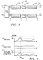
- FIG. 3 a block diagram of a preferred embodiment of a portion of an apparatus 201 for processing base band signals to provide low level signals for amplification that will improve performance of a multi-channel transmitter and more particularly reduce peak to average ratios or peak power requirements that is suitable for use in the transmitter described above will now be discussed and described.
- the apparatus depicted and described is largely or substantially all suitable for and preferably implemented in integrated circuit form, for example in an ASIC including a DSP and supporting hardware and the like.
- the apparatus 201 described here reduces peak power requirements of a multi-channel transmitter and it does so by reducing Peak to Average Ratios (PARs) of signals that are representative in amplitude characteristics of the signals that will be applied to each power amplifier in the multi-channel transmitter.
- PARs Peak to Average Ratios
- This particular embodiment of apparatus 201 may be used together with or in combination with a pre-distortion function such as described above or in lieu thereof.
- the apparatus includes the Transform Matrix (TM), mentioned above, that is coupled to at least one input signal 217 and preferably a plurality of input signals 217 - 219.
- the TM is, preferably a digital FTM 203, for providing a plurality of output signals 221 where each comprises a combination of phase shifted versions of the one or more input signals.
- the processing unit 205 that is coupled to the plurality of output signals 221 and is operable for modifying according to a predetermined algorithm each of the output signals to provide a plurality of modified output signals. More particularly in the depicted embodiment the processing unit is for limiting peak values for each of the plurality of output signals.
- the modified output signals are coupled to the inputs of a second TM preferably a second digital FTM 207, (see FIG.
Landscapes
- Engineering & Computer Science (AREA)
- Physics & Mathematics (AREA)
- Nonlinear Science (AREA)
- Power Engineering (AREA)
- Computer Networks & Wireless Communication (AREA)
- Signal Processing (AREA)
- Amplifiers (AREA)
- Transmitters (AREA)
- Reduction Or Emphasis Of Bandwidth Of Signals (AREA)
Claims (8)
- Ein Mehrkanal-Sender (200), der analoge Fourier-Transformationsmatrizen für die Endverstärkerredundanz verwendet und eine verbesserte Leistungsfähigkeit aufweist, wobei der Mehrkanal-Sender in Kombination folgendes umfasst:ein Gerät zur Verarbeitung von Basisbandsignalen, das ferner folgendes umfasst: eine erste Fourier-Transformationsmatrix (FTM) (203), die mit mindestens einem Eingangssignal (217, 219) zur Bereitstellung einer Vielzahl von Ausgangssignalen (221) gekoppelt ist, wobei jedes eine Kombination von phasenverschobenen Versionen der Eingangssignale umfasst; eine Verarbeitungseinheit (205, 206), die mit den Ausgangssignalen gekoppelt ist, damit gemäß einem vorbestimmten Algorithmus jedes Ausgangssignal modifiziert wird, um eine Vielzahl von modifizierten Ausgangssignalen bereitzustellen; eine zweite FTM (207), die mit der Vielzahl der modifizierten Ausgangssignale zur Zerlegung der modifizierten Ausgangssignale gekoppelt ist, um mindestens ein Ausgang-Basisbandsignal bereitzustellen, wobei jedes Ausgang-Basisbandsignal einem der Eingangssignale entspricht; und eine Kompensationsfunktion, die ausgelegt und mit einem aus der Vielzahl von modifizierten Ausgangssignalen und Ausgang-Basisbandsignalen gekoppelt ist, um gemäß einem Rückführsignal eines aus der Vielzahl von modifizierten Ausgangssignalen und Ausgang-Basisbandsignalen zu kompensieren;einen Mischer (209) zur Umwandlung jedes Ausgang-Basisbandsignals in ein Hochfrequenzsignal, um mindestens ein Hochfrequenzsignal bereitzustellen;eine erste analoge FTM (211) zur Bereitstellung einer Vielzahl von Verstärker-Eingangssignalen, wobei jedes eine Kombination von phasenverschobenen Versionen der Hochfrequenzsignale umfasst;einen Endverstärker (213) mit einer Vielzahl von Verstärkern zur Bereitstellung einer Vielzahl von verstärkten Ausgangssignalen, wobei jeder Verstärker einen Eingang aufweist, der mit einem aus der Vielzahl von Verstärker-Eingangssignalen gekoppelt ist und eines aus der Vielzahl von verstärkten Ausgangssignalen bereitstellt;einen Sampler (245) zur Rückkopplung einer Vielzahl von Teilen eines aus der Vielzahl von Verstärker-Eingangssignalen und der Vielzahl von verstärkten Ausgangssignalen, von denen jedes eines aus der Vielzahl von Verstärker-Eingangssignalen und der Vielzahl von verstärkten Ausgangssignalen darstellt, zu der Kompensationsfunktion, wobei die Vielzahl von Teilen dem Rückführsignal entspricht; undeine zweite analoge FTM (215), die mit der Vielzahl von verstärkten Ausgangssignalen gekoppelt ist, um mindestens ein Sendesignal bereitzustellen, das eins zu eins den Ausgang-Basisbandsignalen entspricht.
- Der Mehrkanal-Sender nach Anspruch 1, wobei die Verarbeitungseinheit ferner folgendes umfasst:eine Begrenzungsfunktion (301), die betrieben wird, um Spitzenwerte jedes Ausgangssignals gemäß einer vorbestimmten Funktion einzuschränken, die die Wahrscheinlichkeit senkt, dass die Spitzenwerte einen vorbestimmten Wert für jedes modifizierte Ausgangssignal übersteigen; undeinen Filter (303), der mit der Begrenzungsfunktion gekoppelt ist, um unerwünschte Signale zu verringern, die aus der Begrenzungsfunktion resultieren.
- Der Mehrkanal-Sender nach Anspruch 1 , wobei die Kompensationsfunktion eine Kompensation gemäß dem Rückführsignal für Variationen in einer Vielzahl von Pfaden zwischen der Kompensationsfunktion und dem Sampler bereitstellt.
- Der Mehrkanal-Sender nach Anspruch 1, wobei die Verarbeitungseinheit ferner eine Vorverzerrungsfunktion umfasst, die jedes Ausgangssignal gemäß einer vorbestimmten Funktion vorverzerrt, die die Effekte auf die Sendesignale verringert, die aus einer Nichtlinearität jedes Verstärkers resultieren.
- Ein Verfahren zur Verbesserung der Leistungsfähigkeit in einem Mehrkanal-Sender unter Verwendung von analogen Fourier-Transformationsmatrizen für die Endverstärkerredundanz, wobei das Verfahren die folgenden Schritte einschließt:Bereitstellen einer Vielzahl von Ausgangssignalen, wobei jedes eine Kombination von phasenverschobenen Versionen mindestens eines Eingangssignals umfasst;Modifizieren gemäß einem vorbestimmten Algorithmus jedes Ausgangssignals, um eine Vielzahl von modifizierten Ausgangssignalen bereitzustellen;Zerlegen der modifizierten Ausgangssignale, um mindestens ein Ausgang-Basisbandsignal bereitzustellen, wobei jedes Ausgang-Basisbandsignal einem der Eingangssignale entspricht;Kompensieren gemäß einem Rückführsignal eines aus der Vielzahl von modifizierten Ausgangssignalen und Ausgang-Basisbandsignalen;Umwandeln jedes Ausgang-Basisbandsignals in ein Hochfrequenzsignal, um mindestens ein Hochfrequenzsignal bereitzustellen;Erzeugen einer Vielzahl von Verstärker-Eingangssignalen, von denen jedes eine Kombination von phasenverschobenen Versionen der Hochfrequenzsignale umfasst, wobei die Verstärker-Eingangssignale den modifizierten Ausgangssignalen entsprechen;Verstärken der Vielzahl von Verstärker-Eingangssignalen, um eine Vielzahl von verstärkten Ausgangssignalen unter Verwendung eines Endverstärkers mit einer Vielzahl von Verstärkern bereitzustellen, wobei jeder Verstärker einen Eingang aufweist, der mit einem aus der Vielzahl von Verstärker-Eingangssignalen gekoppelt ist und eines aus der Vielzahl von verstärkten Ausgangssignalen bereitstellt;Rückkoppeln einer Vielzahl von Teilen eines aus der Vielzahl von Verstärker-Eingangssignalen und der Vielzahl von verstärkten Ausgangssignalen, von denen jedes eines aus der Vielzahl von Verstärker-Eingangssignalen und der Vielzahl von verstärkten Ausgangssignalen darstellt, zu der Kompensationsfunktion, wobei die Vielzahl von Teilen dem Rückführsignal entspricht; undZerlegen der Vielzahl von verstärkten Ausgangssignalen, um mindestens ein Sendesignal bereitzustellen, das eins zu eins den Ausgang-Basisbandsignalen entspricht.
- Das Verfahren nach Anspruch 5, wobei das Bereitstellen einer Vielzahl von Ausgangssignalen eine erste digitale FTM verwendet und das Zerlegen der modifizierten Ausgangssignale eine zweite digitale FTM verwendet, wobei die erste digitale FTM mit einer Vielzahl der Eingangssignale gekoppelt ist, von denen jedes ein Codemultiplex-, ein Zeitmultiplex- und ein Frequenzmultiplex-Basisbandsignal für die Sendung auf einem Funkkanal umfasst.
- Das Verfahren nach Anspruch 5, wobei das Modifizieren gemäß dem vorbestimmten Algorithmus jedes Ausgangssignals ferner folgendes umfasst:Begrenzen jedes Ausgangssignals gemäß einer vorbestimmten Funktion, die die Wahrscheinlichkeit senkt, dass ein Spitzenwert einen vorbestimmten Wert für jedes modifizierte Ausgangssignal übersteigt; undFiltern, nach dem Begrenzen, jedes Ausgangssignals, um unerwünschte Signale zu verringern, die aus der Begrenzung resultieren.
- Das Verfahren nach Anspruch 5, wobei das Kompensieren ferner das Kompensieren eines aus der Vielzahl von modifizierten Ausgangssignalen und Ausgang-Basisbandsignalen gemäß dem Rückführsignal für Variationen in einer Vielzahl von Signalpfaden und Prozessen zwischen den modifizierten Ausgangssignalen und verstärkten Ausgangssignalen einschließt.
Applications Claiming Priority (3)
| Application Number | Priority Date | Filing Date | Title |
|---|---|---|---|
| US101903 | 2002-03-19 | ||
| US10/101,903 US6983026B2 (en) | 2002-03-19 | 2002-03-19 | Method and apparatus using base band transformation to improve transmitter performance |
| PCT/US2003/003876 WO2003081792A1 (en) | 2002-03-19 | 2003-02-07 | Method and apparatus using base band transformation to improve transmitter performance |
Publications (2)
| Publication Number | Publication Date |
|---|---|
| EP1486005A1 EP1486005A1 (de) | 2004-12-15 |
| EP1486005B1 true EP1486005B1 (de) | 2010-04-28 |
Family
ID=28040094
Family Applications (1)
| Application Number | Title | Priority Date | Filing Date |
|---|---|---|---|
| EP03745074A Expired - Lifetime EP1486005B1 (de) | 2002-03-19 | 2003-02-07 | Verfahren und vorrichtung mit basisbandtransformation zur verbesserung von senderleistung |
Country Status (9)
| Country | Link |
|---|---|
| US (1) | US6983026B2 (de) |
| EP (1) | EP1486005B1 (de) |
| JP (1) | JP4261367B2 (de) |
| KR (1) | KR100958046B1 (de) |
| CN (1) | CN100373782C (de) |
| AT (1) | ATE466413T1 (de) |
| AU (1) | AU2003216211A1 (de) |
| DE (1) | DE60332332D1 (de) |
| WO (1) | WO2003081792A1 (de) |
Families Citing this family (62)
| Publication number | Priority date | Publication date | Assignee | Title |
|---|---|---|---|---|
| US6983026B2 (en) | 2002-03-19 | 2006-01-03 | Motorola, Inc. | Method and apparatus using base band transformation to improve transmitter performance |
| US8472897B1 (en) | 2006-12-22 | 2013-06-25 | Dali Systems Co. Ltd. | Power amplifier predistortion methods and apparatus |
| US6985704B2 (en) | 2002-05-01 | 2006-01-10 | Dali Yang | System and method for digital memorized predistortion for wireless communication |
| US8064850B2 (en) * | 2002-05-01 | 2011-11-22 | Dali Systems Co., Ltd. | High efficiency linearization power amplifier for wireless communication |
| US8380143B2 (en) | 2002-05-01 | 2013-02-19 | Dali Systems Co. Ltd | Power amplifier time-delay invariant predistortion methods and apparatus |
| US8811917B2 (en) | 2002-05-01 | 2014-08-19 | Dali Systems Co. Ltd. | Digital hybrid mode power amplifier system |
| JP3913139B2 (ja) * | 2002-08-19 | 2007-05-09 | 沖電気工業株式会社 | Cdma送信装置、cdma多重送信装置、cdma受信装置及びcdma通信システム |
| JP4063612B2 (ja) * | 2002-08-26 | 2008-03-19 | 株式会社エヌ・ティ・ティ・ドコモ | 送信機 |
| US7248656B2 (en) * | 2002-12-02 | 2007-07-24 | Nortel Networks Limited | Digital convertible radio SNR optimization |
| US20040219889A1 (en) * | 2003-04-29 | 2004-11-04 | Walter Honcharenko | Phase-combined transmitter module and modular transmitter system |
| US20050111576A1 (en) * | 2003-11-24 | 2005-05-26 | Kiomars Anvari | Peak-to-average reduction technique for multi-carrier power amplifiers |
| US20050118966A1 (en) * | 2003-12-01 | 2005-06-02 | Kiomars Anvari | Simple Crest Factor reduction technique for multi-carrier signals |
| US7738573B2 (en) * | 2004-10-07 | 2010-06-15 | Microelectronics Technology Inc. | System and method for crest factor reduction |
| WO2006051507A1 (en) * | 2004-11-12 | 2006-05-18 | Koninklijke Philips Electronics N.V. | Radio communication system, receiver and transmitter |
| EP1659703A1 (de) * | 2004-11-17 | 2006-05-24 | Alcatel | Verfahren und Vorrichtung zur Verringerung des Verhältnisses von Spitzen- zu Durchschnittsleistung in Mobiltelephonen |
| US20060105723A1 (en) * | 2004-11-17 | 2006-05-18 | Kiomars Anvari | Simple crest factor reduction technique for non-constant envelope signals |
| US7668266B2 (en) * | 2005-03-18 | 2010-02-23 | Georgia Tech Research Corporation | Crest factor reduction in OFDM using blind selected pilot tone modulation |
| US7586995B1 (en) * | 2005-04-18 | 2009-09-08 | Altera Corporation | Peak windowing for crest factor reduction |
| US8145251B2 (en) * | 2006-01-23 | 2012-03-27 | Motorola Mobility, Inc. | Power control in schedulable wireless communication terminal |
| US20070173260A1 (en) * | 2006-01-23 | 2007-07-26 | Love Robert T | Wireless communication network scheduling |
| JP4680077B2 (ja) * | 2006-02-02 | 2011-05-11 | 三菱電機株式会社 | Ofdm通信器 |
| JP4750592B2 (ja) * | 2006-03-17 | 2011-08-17 | 富士通株式会社 | ピーク抑圧方法、ピーク抑圧装置、無線送信装置 |
| US7738594B2 (en) * | 2006-06-30 | 2010-06-15 | Intel Corporation | Method to maintain RF power amplifier linearity in varying load VSWR conditions without isolator |
| US9622190B2 (en) | 2006-07-25 | 2017-04-11 | Google Technology Holdings LLC | Spectrum emission level variation in schedulable wireless communication terminal |
| US20080025254A1 (en) * | 2006-07-25 | 2008-01-31 | Motorola Inc | Spectrum emission level variation in schedulable wireless communication terminal |
| US7480346B2 (en) * | 2006-09-13 | 2009-01-20 | Motorola, Inc. | Method and apparatus for improving sector to sector isolation in a Fourier transform matrix system |
| US8411709B1 (en) | 2006-11-27 | 2013-04-02 | Marvell International Ltd. | Use of previously buffered state information to decode in an hybrid automatic repeat request (H-ARQ) transmission mode |
| US9026067B2 (en) | 2007-04-23 | 2015-05-05 | Dali Systems Co. Ltd. | Remotely reconfigurable power amplifier system and method |
| KR20100014339A (ko) * | 2006-12-26 | 2010-02-10 | 달리 시스템즈 씨오. 엘티디. | 다중 채널 광대역 통신 시스템에서의 기저 대역 전치 왜곡 선형화를 위한 방법 및 시스템 |
| US8274332B2 (en) | 2007-04-23 | 2012-09-25 | Dali Systems Co. Ltd. | N-way Doherty distributed power amplifier with power tracking |
| US8224266B2 (en) * | 2007-08-30 | 2012-07-17 | Dali Systems Co., Ltd. | Power amplifier predistortion methods and apparatus using envelope and phase detector |
| US8897393B1 (en) | 2007-10-16 | 2014-11-25 | Marvell International Ltd. | Protected codebook selection at receiver for transmit beamforming |
| US8542725B1 (en) | 2007-11-14 | 2013-09-24 | Marvell International Ltd. | Decision feedback equalization for signals having unequally distributed patterns |
| KR101669173B1 (ko) | 2007-12-07 | 2016-10-25 | 달리 시스템즈 씨오. 엘티디. | 베이스밴드-도출형 광대역 rf 디지털 전치 왜곡 시스템 |
| US8140606B2 (en) * | 2007-12-17 | 2012-03-20 | Motorola Mobility, Inc. | Method and apparatus for a fail safe fourier transform matrix |
| US8565325B1 (en) | 2008-03-18 | 2013-10-22 | Marvell International Ltd. | Wireless device communication in the 60GHz band |
| US8498342B1 (en) | 2008-07-29 | 2013-07-30 | Marvell International Ltd. | Deblocking filtering |
| US8761261B1 (en) | 2008-07-29 | 2014-06-24 | Marvell International Ltd. | Encoding using motion vectors |
| US8345533B1 (en) | 2008-08-18 | 2013-01-01 | Marvell International Ltd. | Frame synchronization techniques |
| US8681893B1 (en) | 2008-10-08 | 2014-03-25 | Marvell International Ltd. | Generating pulses using a look-up table |
| US8761834B2 (en) * | 2008-12-31 | 2014-06-24 | Motorola Mobility Llc | Method and apparatus for antenna selection and power control in a multiple input multiple output wireless communication system |
| US8520771B1 (en) * | 2009-04-29 | 2013-08-27 | Marvell International Ltd. | WCDMA modulation |
| US8532215B2 (en) * | 2009-09-14 | 2013-09-10 | Her Majesty The Queen In Right Of Canada, As Represented By The Minister Of Industry, Through The Communications Research Centre Canada | Multi-carrier amplifier linearization system and method |
| US8351877B2 (en) | 2010-12-21 | 2013-01-08 | Dali Systems Co. Ltfd. | Multi-band wideband power amplifier digital predistorition system and method |
| JP5744910B2 (ja) * | 2009-12-21 | 2015-07-08 | ダリ システムズ カンパニー リミテッド | 無線通信のための高効率、リモートで再構成可能なリモート無線ヘッドユニットのシステム及び方法 |
| EP3110231B1 (de) | 2009-12-21 | 2018-05-02 | Dali Systems Co. Ltd. | Effizientes fernkonfigurierbares fernfunkkopfsystem und verfahren für die drahtlose kommunikation |
| CN106160674A (zh) | 2009-12-21 | 2016-11-23 | 大力系统有限公司 | 用于改善发射机与接收机之间的隔离的系统 |
| US8542768B2 (en) | 2009-12-21 | 2013-09-24 | Dali Systems Co. Ltd. | High efficiency, remotely reconfigurable remote radio head unit system and method for wireless communications |
| US8351543B2 (en) * | 2009-12-21 | 2013-01-08 | Ubidyne, Inc. | Active antenna array with modulator-based pre-distortion |
| US8817771B1 (en) | 2010-07-16 | 2014-08-26 | Marvell International Ltd. | Method and apparatus for detecting a boundary of a data frame in a communication network |
| KR102136940B1 (ko) | 2010-09-14 | 2020-07-23 | 달리 시스템즈 씨오. 엘티디. | 원격으로 재구성가능한 분산 안테나 시스템 및 방법 |
| US8750410B2 (en) * | 2010-09-22 | 2014-06-10 | Texas Instruments Incorporated | Multi-band power amplifier digital predistortion system and method |
| US9565655B2 (en) | 2011-04-13 | 2017-02-07 | Google Technology Holdings LLC | Method and apparatus to detect the transmission bandwidth configuration of a channel in connection with reducing interference between channels in wireless communication systems |
| US8934500B2 (en) | 2011-04-13 | 2015-01-13 | Motorola Mobility Llc | Method and apparatus using two radio access technologies for scheduling resources in wireless communication systems |
| US9077571B2 (en) * | 2011-09-09 | 2015-07-07 | Nxp B.V. | Adaptive equalizer and/or antenna tuning |
| US8576943B2 (en) * | 2011-09-09 | 2013-11-05 | Telefonaktiebolaget L M Ericsson (Publ) | Linearization for a single power amplifier in a multi-band transmitter |
| JP5794163B2 (ja) * | 2012-02-03 | 2015-10-14 | アイコム株式会社 | 通信機および通信方法 |
| CN102594749A (zh) * | 2012-02-28 | 2012-07-18 | 中兴通讯股份有限公司 | 一种数字预失真处理方法及装置 |
| US9191041B2 (en) * | 2013-06-05 | 2015-11-17 | Telefonaktiebolaget L M Ericsson (Publ) | Digital predistortion of wideband power amplifiers with reduced observation bandwidth |
| KR102140299B1 (ko) * | 2014-01-27 | 2020-07-31 | 한국전자통신연구원 | 논리 레벨에 대응하는 전기 특성 값을 조절하는 송신 장치 및 그것의 신호 전송 방법 |
| WO2018224161A1 (en) * | 2017-06-09 | 2018-12-13 | Nokia Technologies Oy | Reducing distortions in amplified signals to be radiated by an antenna |
| US10594530B2 (en) * | 2018-05-29 | 2020-03-17 | Qualcomm Incorporated | Techniques for successive peak reduction crest factor reduction |
Family Cites Families (13)
| Publication number | Priority date | Publication date | Assignee | Title |
|---|---|---|---|---|
| US5287387A (en) | 1992-03-06 | 1994-02-15 | Motorola, Inc. | Low splatter peak-to-average signal reduction |
| US5574967A (en) | 1994-01-11 | 1996-11-12 | Ericsson Ge Mobile Communications, Inc. | Waste energy control and management in power amplifiers |
| US5638403A (en) | 1995-04-28 | 1997-06-10 | Motorola, Inc. | Low-splatter peak-to-average signal reduction with interpolation |
| US5862457A (en) | 1995-12-21 | 1999-01-19 | Lucent Technologies, Inc. | Multichannel predistortion linearizer |
| US5732333A (en) * | 1996-02-14 | 1998-03-24 | Glenayre Electronics, Inc. | Linear transmitter using predistortion |
| GB2313525B (en) * | 1996-05-24 | 2000-06-07 | Motorola Ltd | Filter for multicarrier communication system and method for peak power control therein |
| US5920808A (en) * | 1996-12-12 | 1999-07-06 | Glenayre Electronics, Inc. | Method and apparatus for reducing key-up distortion by pre-heating transistors |
| US5886573A (en) | 1998-03-06 | 1999-03-23 | Fujant, Inc. | Amplification using amplitude reconstruction of amplitude and/or angle modulated carrier |
| US6381212B1 (en) * | 1998-06-17 | 2002-04-30 | Radio Frequency Systems, Inc. | Power sharing amplifier system for amplifying multiple input signals with shared power amplifiers |
| US6236837B1 (en) | 1998-07-30 | 2001-05-22 | Motorola, Inc. | Polynomial Predistortion linearizing device, method, phone and base station |
| US6304140B1 (en) | 2000-06-12 | 2001-10-16 | Motorola, Inc. | Digital predistortion for amplifiers |
| US7065154B2 (en) * | 2000-12-29 | 2006-06-20 | Nokia Corporation | Baseband predistortion method for multicarrier transmitters |
| US6983026B2 (en) | 2002-03-19 | 2006-01-03 | Motorola, Inc. | Method and apparatus using base band transformation to improve transmitter performance |
-
2002
- 2002-03-19 US US10/101,903 patent/US6983026B2/en not_active Expired - Lifetime
-
2003
- 2003-02-07 WO PCT/US2003/003876 patent/WO2003081792A1/en not_active Ceased
- 2003-02-07 CN CNB038062771A patent/CN100373782C/zh not_active Expired - Lifetime
- 2003-02-07 KR KR1020047014701A patent/KR100958046B1/ko not_active Expired - Lifetime
- 2003-02-07 DE DE60332332T patent/DE60332332D1/de not_active Expired - Lifetime
- 2003-02-07 EP EP03745074A patent/EP1486005B1/de not_active Expired - Lifetime
- 2003-02-07 JP JP2003579378A patent/JP4261367B2/ja not_active Expired - Lifetime
- 2003-02-07 AT AT03745074T patent/ATE466413T1/de not_active IP Right Cessation
- 2003-02-07 AU AU2003216211A patent/AU2003216211A1/en not_active Abandoned
Also Published As
| Publication number | Publication date |
|---|---|
| US20030179829A1 (en) | 2003-09-25 |
| CN100373782C (zh) | 2008-03-05 |
| WO2003081792A1 (en) | 2003-10-02 |
| EP1486005A1 (de) | 2004-12-15 |
| AU2003216211A1 (en) | 2003-10-08 |
| DE60332332D1 (de) | 2010-06-10 |
| US6983026B2 (en) | 2006-01-03 |
| KR100958046B1 (ko) | 2010-05-17 |
| JP2006509378A (ja) | 2006-03-16 |
| CN1647395A (zh) | 2005-07-27 |
| KR20040091764A (ko) | 2004-10-28 |
| ATE466413T1 (de) | 2010-05-15 |
| JP4261367B2 (ja) | 2009-04-30 |
Similar Documents
| Publication | Publication Date | Title |
|---|---|---|
| US6983026B2 (en) | Method and apparatus using base band transformation to improve transmitter performance | |
| US11418155B2 (en) | Digital hybrid mode power amplifier system | |
| EP1485997B1 (de) | Vorrichtung zur reduktion von senderleistungsbedarf unter verwendung von dualen matrizen , und verfahren dazu | |
| US9432228B2 (en) | Digital pre-distortion filter system and method | |
| US7259630B2 (en) | Elimination of peak clipping and improved efficiency for RF power amplifiers with a predistorter | |
| JP5591106B2 (ja) | デジタルハイブリッドモード電力増幅器システム | |
| EP1486044B1 (de) | Vorrichtung zur verbesserung der senderredundanz , und verfahren dazu | |
| CN102948071B (zh) | 调制不可知的数字混合模式功率放大器系统及方法 | |
| US6963242B2 (en) | Predistorter for phase modulated signals with low peak to average ratios | |
| US20040136470A1 (en) | Uncorrelated adaptive predistorter | |
| US20040057533A1 (en) | System and method for performing predistortion at intermediate frequency | |
| Guo et al. | Enhanced power efficiency of mobile OFDM radio using predistortion and post-compensation | |
| Kwan et al. | High performance wideband digital predistortion platform for 3G+ applications with better than 55dBc over 40 MHz bandwidth | |
| Woo et al. | Wideband predistortion linearization system for RF power amplifiers using an envelope modulation technique | |
| Goswami et al. | Satellite Digital Channelizer with Predistorted High-Power Amplifier |
Legal Events
| Date | Code | Title | Description |
|---|---|---|---|
| PUAI | Public reference made under article 153(3) epc to a published international application that has entered the european phase |
Free format text: ORIGINAL CODE: 0009012 |
|
| 17P | Request for examination filed |
Effective date: 20041013 |
|
| AK | Designated contracting states |
Kind code of ref document: A1 Designated state(s): AT BE BG CH CY CZ DE DK EE ES FI FR GB GR HU IE IT LI LU MC NL PT SE SI SK TR |
|
| AX | Request for extension of the european patent |
Extension state: AL LT LV MK RO |
|
| 17Q | First examination report despatched |
Effective date: 20081028 |
|
| GRAP | Despatch of communication of intention to grant a patent |
Free format text: ORIGINAL CODE: EPIDOSNIGR1 |
|
| GRAS | Grant fee paid |
Free format text: ORIGINAL CODE: EPIDOSNIGR3 |
|
| GRAA | (expected) grant |
Free format text: ORIGINAL CODE: 0009210 |
|
| AK | Designated contracting states |
Kind code of ref document: B1 Designated state(s): AT BE BG CH CY CZ DE DK EE ES FI FR GB GR HU IE IT LI LU MC NL PT SE SI SK TR |
|
| REG | Reference to a national code |
Ref country code: GB Ref legal event code: FG4D |
|
| REG | Reference to a national code |
Ref country code: CH Ref legal event code: EP |
|
| REG | Reference to a national code |
Ref country code: IE Ref legal event code: FG4D |
|
| REF | Corresponds to: |
Ref document number: 60332332 Country of ref document: DE Date of ref document: 20100610 Kind code of ref document: P |
|
| REG | Reference to a national code |
Ref country code: SE Ref legal event code: TRGR |
|
| REG | Reference to a national code |
Ref country code: NL Ref legal event code: VDEP Effective date: 20100428 |
|
| PG25 | Lapsed in a contracting state [announced via postgrant information from national office to epo] |
Ref country code: ES Free format text: LAPSE BECAUSE OF FAILURE TO SUBMIT A TRANSLATION OF THE DESCRIPTION OR TO PAY THE FEE WITHIN THE PRESCRIBED TIME-LIMIT Effective date: 20100808 Ref country code: NL Free format text: LAPSE BECAUSE OF FAILURE TO SUBMIT A TRANSLATION OF THE DESCRIPTION OR TO PAY THE FEE WITHIN THE PRESCRIBED TIME-LIMIT Effective date: 20100428 |
|
| PG25 | Lapsed in a contracting state [announced via postgrant information from national office to epo] |
Ref country code: AT Free format text: LAPSE BECAUSE OF FAILURE TO SUBMIT A TRANSLATION OF THE DESCRIPTION OR TO PAY THE FEE WITHIN THE PRESCRIBED TIME-LIMIT Effective date: 20100428 Ref country code: FI Free format text: LAPSE BECAUSE OF FAILURE TO SUBMIT A TRANSLATION OF THE DESCRIPTION OR TO PAY THE FEE WITHIN THE PRESCRIBED TIME-LIMIT Effective date: 20100428 Ref country code: SI Free format text: LAPSE BECAUSE OF FAILURE TO SUBMIT A TRANSLATION OF THE DESCRIPTION OR TO PAY THE FEE WITHIN THE PRESCRIBED TIME-LIMIT Effective date: 20100428 |
|
| PG25 | Lapsed in a contracting state [announced via postgrant information from national office to epo] |
Ref country code: GR Free format text: LAPSE BECAUSE OF FAILURE TO SUBMIT A TRANSLATION OF THE DESCRIPTION OR TO PAY THE FEE WITHIN THE PRESCRIBED TIME-LIMIT Effective date: 20100729 Ref country code: CY Free format text: LAPSE BECAUSE OF FAILURE TO SUBMIT A TRANSLATION OF THE DESCRIPTION OR TO PAY THE FEE WITHIN THE PRESCRIBED TIME-LIMIT Effective date: 20100428 |
|
| PG25 | Lapsed in a contracting state [announced via postgrant information from national office to epo] |
Ref country code: EE Free format text: LAPSE BECAUSE OF FAILURE TO SUBMIT A TRANSLATION OF THE DESCRIPTION OR TO PAY THE FEE WITHIN THE PRESCRIBED TIME-LIMIT Effective date: 20100428 Ref country code: DK Free format text: LAPSE BECAUSE OF FAILURE TO SUBMIT A TRANSLATION OF THE DESCRIPTION OR TO PAY THE FEE WITHIN THE PRESCRIBED TIME-LIMIT Effective date: 20100428 Ref country code: PT Free format text: LAPSE BECAUSE OF FAILURE TO SUBMIT A TRANSLATION OF THE DESCRIPTION OR TO PAY THE FEE WITHIN THE PRESCRIBED TIME-LIMIT Effective date: 20100830 |
|
| REG | Reference to a national code |
Ref country code: GB Ref legal event code: 732E Free format text: REGISTERED BETWEEN 20110127 AND 20110202 |
|
| PG25 | Lapsed in a contracting state [announced via postgrant information from national office to epo] |
Ref country code: SK Free format text: LAPSE BECAUSE OF FAILURE TO SUBMIT A TRANSLATION OF THE DESCRIPTION OR TO PAY THE FEE WITHIN THE PRESCRIBED TIME-LIMIT Effective date: 20100428 Ref country code: BE Free format text: LAPSE BECAUSE OF FAILURE TO SUBMIT A TRANSLATION OF THE DESCRIPTION OR TO PAY THE FEE WITHIN THE PRESCRIBED TIME-LIMIT Effective date: 20100428 Ref country code: CZ Free format text: LAPSE BECAUSE OF FAILURE TO SUBMIT A TRANSLATION OF THE DESCRIPTION OR TO PAY THE FEE WITHIN THE PRESCRIBED TIME-LIMIT Effective date: 20100428 |
|
| PLBE | No opposition filed within time limit |
Free format text: ORIGINAL CODE: 0009261 |
|
| STAA | Information on the status of an ep patent application or granted ep patent |
Free format text: STATUS: NO OPPOSITION FILED WITHIN TIME LIMIT |
|
| PG25 | Lapsed in a contracting state [announced via postgrant information from national office to epo] |
Ref country code: IT Free format text: LAPSE BECAUSE OF FAILURE TO SUBMIT A TRANSLATION OF THE DESCRIPTION OR TO PAY THE FEE WITHIN THE PRESCRIBED TIME-LIMIT Effective date: 20100428 |
|
| 26N | No opposition filed |
Effective date: 20110131 |
|
| PG25 | Lapsed in a contracting state [announced via postgrant information from national office to epo] |
Ref country code: MC Free format text: LAPSE BECAUSE OF NON-PAYMENT OF DUE FEES Effective date: 20110228 |
|
| REG | Reference to a national code |
Ref country code: CH Ref legal event code: PL |
|
| PG25 | Lapsed in a contracting state [announced via postgrant information from national office to epo] |
Ref country code: LI Free format text: LAPSE BECAUSE OF NON-PAYMENT OF DUE FEES Effective date: 20110228 Ref country code: CH Free format text: LAPSE BECAUSE OF NON-PAYMENT OF DUE FEES Effective date: 20110228 |
|
| REG | Reference to a national code |
Ref country code: FR Ref legal event code: ST Effective date: 20111102 |
|
| REG | Reference to a national code |
Ref country code: IE Ref legal event code: MM4A |
|
| REG | Reference to a national code |
Ref country code: DE Ref legal event code: R119 Ref document number: 60332332 Country of ref document: DE Effective date: 20110901 |
|
| PG25 | Lapsed in a contracting state [announced via postgrant information from national office to epo] |
Ref country code: FR Free format text: LAPSE BECAUSE OF NON-PAYMENT OF DUE FEES Effective date: 20110228 Ref country code: IE Free format text: LAPSE BECAUSE OF NON-PAYMENT OF DUE FEES Effective date: 20110207 |
|
| PG25 | Lapsed in a contracting state [announced via postgrant information from national office to epo] |
Ref country code: LU Free format text: LAPSE BECAUSE OF NON-PAYMENT OF DUE FEES Effective date: 20110207 |
|
| PG25 | Lapsed in a contracting state [announced via postgrant information from national office to epo] |
Ref country code: DE Free format text: LAPSE BECAUSE OF NON-PAYMENT OF DUE FEES Effective date: 20110901 |
|
| PG25 | Lapsed in a contracting state [announced via postgrant information from national office to epo] |
Ref country code: BG Free format text: LAPSE BECAUSE OF FAILURE TO SUBMIT A TRANSLATION OF THE DESCRIPTION OR TO PAY THE FEE WITHIN THE PRESCRIBED TIME-LIMIT Effective date: 20100728 Ref country code: TR Free format text: LAPSE BECAUSE OF FAILURE TO SUBMIT A TRANSLATION OF THE DESCRIPTION OR TO PAY THE FEE WITHIN THE PRESCRIBED TIME-LIMIT Effective date: 20100428 |
|
| PG25 | Lapsed in a contracting state [announced via postgrant information from national office to epo] |
Ref country code: HU Free format text: LAPSE BECAUSE OF FAILURE TO SUBMIT A TRANSLATION OF THE DESCRIPTION OR TO PAY THE FEE WITHIN THE PRESCRIBED TIME-LIMIT Effective date: 20100428 |
|
| REG | Reference to a national code |
Ref country code: GB Ref legal event code: 732E Free format text: REGISTERED BETWEEN 20170831 AND 20170906 |
|
| PGFP | Annual fee paid to national office [announced via postgrant information from national office to epo] |
Ref country code: SE Payment date: 20190227 Year of fee payment: 17 |
|
| REG | Reference to a national code |
Ref country code: SE Ref legal event code: EUG |
|
| PG25 | Lapsed in a contracting state [announced via postgrant information from national office to epo] |
Ref country code: SE Free format text: LAPSE BECAUSE OF NON-PAYMENT OF DUE FEES Effective date: 20200208 |
|
| PGFP | Annual fee paid to national office [announced via postgrant information from national office to epo] |
Ref country code: GB Payment date: 20220225 Year of fee payment: 20 |
|
| REG | Reference to a national code |
Ref country code: GB Ref legal event code: PE20 Expiry date: 20230206 |
|
| PG25 | Lapsed in a contracting state [announced via postgrant information from national office to epo] |
Ref country code: GB Free format text: LAPSE BECAUSE OF EXPIRATION OF PROTECTION Effective date: 20230206 |