EP1486253A1 - Appareillage de reformage avec un absorbant pour hydrocarbures - Google Patents
Appareillage de reformage avec un absorbant pour hydrocarbures Download PDFInfo
- Publication number
- EP1486253A1 EP1486253A1 EP04013642A EP04013642A EP1486253A1 EP 1486253 A1 EP1486253 A1 EP 1486253A1 EP 04013642 A EP04013642 A EP 04013642A EP 04013642 A EP04013642 A EP 04013642A EP 1486253 A1 EP1486253 A1 EP 1486253A1
- Authority
- EP
- European Patent Office
- Prior art keywords
- fuel
- hydrocarbon
- reformer
- temperature
- absorber
- Prior art date
- Legal status (The legal status is an assumption and is not a legal conclusion. Google has not performed a legal analysis and makes no representation as to the accuracy of the status listed.)
- Withdrawn
Links
Images

Classifications
-
- B—PERFORMING OPERATIONS; TRANSPORTING
- B01—PHYSICAL OR CHEMICAL PROCESSES OR APPARATUS IN GENERAL
- B01D—SEPARATION
- B01D53/00—Separation of gases or vapours; Recovering vapours of volatile solvents from gases; Chemical or biological purification of waste gases, e.g. engine exhaust gases, smoke, fumes, flue gases, aerosols
- B01D53/02—Separation of gases or vapours; Recovering vapours of volatile solvents from gases; Chemical or biological purification of waste gases, e.g. engine exhaust gases, smoke, fumes, flue gases, aerosols by adsorption, e.g. preparative gas chromatography
- B01D53/04—Separation of gases or vapours; Recovering vapours of volatile solvents from gases; Chemical or biological purification of waste gases, e.g. engine exhaust gases, smoke, fumes, flue gases, aerosols by adsorption, e.g. preparative gas chromatography with stationary adsorbents
- B01D53/0407—Constructional details of adsorbing systems
-
- B—PERFORMING OPERATIONS; TRANSPORTING
- B01—PHYSICAL OR CHEMICAL PROCESSES OR APPARATUS IN GENERAL
- B01J—CHEMICAL OR PHYSICAL PROCESSES, e.g. CATALYSIS OR COLLOID CHEMISTRY; THEIR RELEVANT APPARATUS
- B01J8/00—Chemical or physical processes in general, conducted in the presence of fluids and solid particles; Apparatus for such processes
- B01J8/02—Chemical or physical processes in general, conducted in the presence of fluids and solid particles; Apparatus for such processes with stationary particles, e.g. in fixed beds
- B01J8/04—Chemical or physical processes in general, conducted in the presence of fluids and solid particles; Apparatus for such processes with stationary particles, e.g. in fixed beds the fluid passing successively through two or more beds
- B01J8/0403—Chemical or physical processes in general, conducted in the presence of fluids and solid particles; Apparatus for such processes with stationary particles, e.g. in fixed beds the fluid passing successively through two or more beds the fluid flow within the beds being predominantly horizontal
- B01J8/0423—Chemical or physical processes in general, conducted in the presence of fluids and solid particles; Apparatus for such processes with stationary particles, e.g. in fixed beds the fluid passing successively through two or more beds the fluid flow within the beds being predominantly horizontal through two or more otherwise shaped beds
- B01J8/0442—Chemical or physical processes in general, conducted in the presence of fluids and solid particles; Apparatus for such processes with stationary particles, e.g. in fixed beds the fluid passing successively through two or more beds the fluid flow within the beds being predominantly horizontal through two or more otherwise shaped beds the beds being placed in separate reactors
-
- C—CHEMISTRY; METALLURGY
- C01—INORGANIC CHEMISTRY
- C01B—NON-METALLIC ELEMENTS; COMPOUNDS THEREOF; METALLOIDS OR COMPOUNDS THEREOF NOT COVERED BY SUBCLASS C01C
- C01B3/00—Hydrogen; Gaseous mixtures containing hydrogen; Separation of hydrogen from mixtures containing it; Purification of hydrogen; Reversible storage of hydrogen
- C01B3/02—Production of hydrogen; Production of gaseous mixtures containing hydrogen
- C01B3/32—Production of hydrogen; Production of gaseous mixtures containing hydrogen by reaction of gaseous or liquid organic compounds with gasifying agents, e.g. water, carbon dioxide or air
- C01B3/34—Production of hydrogen; Production of gaseous mixtures containing hydrogen by reaction of gaseous or liquid organic compounds with gasifying agents, e.g. water, carbon dioxide or air by reaction of hydrocarbons with gasifying agents
- C01B3/38—Production of hydrogen; Production of gaseous mixtures containing hydrogen by reaction of gaseous or liquid organic compounds with gasifying agents, e.g. water, carbon dioxide or air by reaction of hydrocarbons with gasifying agents using catalysts
-
- C—CHEMISTRY; METALLURGY
- C01—INORGANIC CHEMISTRY
- C01B—NON-METALLIC ELEMENTS; COMPOUNDS THEREOF; METALLOIDS OR COMPOUNDS THEREOF NOT COVERED BY SUBCLASS C01C
- C01B3/00—Hydrogen; Gaseous mixtures containing hydrogen; Separation of hydrogen from mixtures containing it; Purification of hydrogen; Reversible storage of hydrogen
- C01B3/50—Separation of hydrogen or hydrogen-containing gases from gaseous mixtures, e.g. purification
- C01B3/56—Separation of hydrogen or hydrogen-containing gases from gaseous mixtures, e.g. purification by contacting with solids; Regeneration of used solids
-
- H—ELECTRICITY
- H01—ELECTRIC ELEMENTS
- H01M—PROCESSES OR MEANS, e.g. BATTERIES, FOR THE DIRECT CONVERSION OF CHEMICAL ENERGY INTO ELECTRICAL ENERGY
- H01M8/00—Fuel cells; Manufacture thereof
- H01M8/06—Combination of fuel cells with means for production of reactants or for treatment of residues
- H01M8/0606—Combination of fuel cells with means for production of reactants or for treatment of residues with means for production of gaseous reactants
- H01M8/0612—Combination of fuel cells with means for production of reactants or for treatment of residues with means for production of gaseous reactants from carbon-containing material
-
- H—ELECTRICITY
- H01—ELECTRIC ELEMENTS
- H01M—PROCESSES OR MEANS, e.g. BATTERIES, FOR THE DIRECT CONVERSION OF CHEMICAL ENERGY INTO ELECTRICAL ENERGY
- H01M8/00—Fuel cells; Manufacture thereof
- H01M8/06—Combination of fuel cells with means for production of reactants or for treatment of residues
- H01M8/0662—Treatment of gaseous reactants or gaseous residues, e.g. cleaning
- H01M8/0668—Removal of carbon monoxide or carbon dioxide
-
- B—PERFORMING OPERATIONS; TRANSPORTING
- B01—PHYSICAL OR CHEMICAL PROCESSES OR APPARATUS IN GENERAL
- B01D—SEPARATION
- B01D2253/00—Adsorbents used in seperation treatment of gases and vapours
- B01D2253/10—Inorganic adsorbents
- B01D2253/106—Silica or silicates
- B01D2253/108—Zeolites
-
- B—PERFORMING OPERATIONS; TRANSPORTING
- B01—PHYSICAL OR CHEMICAL PROCESSES OR APPARATUS IN GENERAL
- B01D—SEPARATION
- B01D2256/00—Main component in the product gas stream after treatment
- B01D2256/16—Hydrogen
-
- B—PERFORMING OPERATIONS; TRANSPORTING
- B01—PHYSICAL OR CHEMICAL PROCESSES OR APPARATUS IN GENERAL
- B01D—SEPARATION
- B01D2257/00—Components to be removed
- B01D2257/70—Organic compounds not provided for in groups B01D2257/00 - B01D2257/602
- B01D2257/702—Hydrocarbons
-
- B—PERFORMING OPERATIONS; TRANSPORTING
- B01—PHYSICAL OR CHEMICAL PROCESSES OR APPARATUS IN GENERAL
- B01D—SEPARATION
- B01D2259/00—Type of treatment
- B01D2259/40—Further details for adsorption processes and devices
- B01D2259/40083—Regeneration of adsorbents in processes other than pressure or temperature swing adsorption
- B01D2259/40088—Regeneration of adsorbents in processes other than pressure or temperature swing adsorption by heating
-
- B—PERFORMING OPERATIONS; TRANSPORTING
- B01—PHYSICAL OR CHEMICAL PROCESSES OR APPARATUS IN GENERAL
- B01D—SEPARATION
- B01D2259/00—Type of treatment
- B01D2259/45—Gas separation or purification devices adapted for specific applications
- B01D2259/4566—Gas separation or purification devices adapted for specific applications for use in transportation means
-
- B—PERFORMING OPERATIONS; TRANSPORTING
- B01—PHYSICAL OR CHEMICAL PROCESSES OR APPARATUS IN GENERAL
- B01J—CHEMICAL OR PHYSICAL PROCESSES, e.g. CATALYSIS OR COLLOID CHEMISTRY; THEIR RELEVANT APPARATUS
- B01J2208/00—Processes carried out in the presence of solid particles; Reactors therefor
- B01J2208/00008—Controlling the process
- B01J2208/00017—Controlling the temperature
- B01J2208/00504—Controlling the temperature by means of a burner
-
- B—PERFORMING OPERATIONS; TRANSPORTING
- B01—PHYSICAL OR CHEMICAL PROCESSES OR APPARATUS IN GENERAL
- B01J—CHEMICAL OR PHYSICAL PROCESSES, e.g. CATALYSIS OR COLLOID CHEMISTRY; THEIR RELEVANT APPARATUS
- B01J2208/00—Processes carried out in the presence of solid particles; Reactors therefor
- B01J2208/00008—Controlling the process
- B01J2208/00017—Controlling the temperature
- B01J2208/0053—Controlling multiple zones along the direction of flow, e.g. pre-heating and after-cooling
-
- B—PERFORMING OPERATIONS; TRANSPORTING
- B01—PHYSICAL OR CHEMICAL PROCESSES OR APPARATUS IN GENERAL
- B01J—CHEMICAL OR PHYSICAL PROCESSES, e.g. CATALYSIS OR COLLOID CHEMISTRY; THEIR RELEVANT APPARATUS
- B01J2208/00—Processes carried out in the presence of solid particles; Reactors therefor
- B01J2208/00008—Controlling the process
- B01J2208/00716—Means for reactor start-up
-
- B—PERFORMING OPERATIONS; TRANSPORTING
- B01—PHYSICAL OR CHEMICAL PROCESSES OR APPARATUS IN GENERAL
- B01J—CHEMICAL OR PHYSICAL PROCESSES, e.g. CATALYSIS OR COLLOID CHEMISTRY; THEIR RELEVANT APPARATUS
- B01J2219/00—Chemical, physical or physico-chemical processes in general; Their relevant apparatus
- B01J2219/00002—Chemical plants
- B01J2219/00004—Scale aspects
- B01J2219/00006—Large-scale industrial plants
-
- B—PERFORMING OPERATIONS; TRANSPORTING
- B01—PHYSICAL OR CHEMICAL PROCESSES OR APPARATUS IN GENERAL
- B01J—CHEMICAL OR PHYSICAL PROCESSES, e.g. CATALYSIS OR COLLOID CHEMISTRY; THEIR RELEVANT APPARATUS
- B01J2219/00—Chemical, physical or physico-chemical processes in general; Their relevant apparatus
- B01J2219/00049—Controlling or regulating processes
- B01J2219/00191—Control algorithm
- B01J2219/00211—Control algorithm comparing a sensed parameter with a pre-set value
- B01J2219/00218—Dynamically variable (in-line) parameter values
-
- B—PERFORMING OPERATIONS; TRANSPORTING
- B01—PHYSICAL OR CHEMICAL PROCESSES OR APPARATUS IN GENERAL
- B01J—CHEMICAL OR PHYSICAL PROCESSES, e.g. CATALYSIS OR COLLOID CHEMISTRY; THEIR RELEVANT APPARATUS
- B01J2219/00—Chemical, physical or physico-chemical processes in general; Their relevant apparatus
- B01J2219/00049—Controlling or regulating processes
- B01J2219/00191—Control algorithm
- B01J2219/00222—Control algorithm taking actions
- B01J2219/00227—Control algorithm taking actions modifying the operating conditions
- B01J2219/00238—Control algorithm taking actions modifying the operating conditions of the heat exchange system
-
- C—CHEMISTRY; METALLURGY
- C01—INORGANIC CHEMISTRY
- C01B—NON-METALLIC ELEMENTS; COMPOUNDS THEREOF; METALLOIDS OR COMPOUNDS THEREOF NOT COVERED BY SUBCLASS C01C
- C01B2203/00—Integrated processes for the production of hydrogen or synthesis gas
-
- C—CHEMISTRY; METALLURGY
- C01—INORGANIC CHEMISTRY
- C01B—NON-METALLIC ELEMENTS; COMPOUNDS THEREOF; METALLOIDS OR COMPOUNDS THEREOF NOT COVERED BY SUBCLASS C01C
- C01B2203/00—Integrated processes for the production of hydrogen or synthesis gas
- C01B2203/02—Processes for making hydrogen or synthesis gas
- C01B2203/0205—Processes for making hydrogen or synthesis gas containing a reforming step
- C01B2203/0211—Processes for making hydrogen or synthesis gas containing a reforming step containing a non-catalytic reforming step
-
- C—CHEMISTRY; METALLURGY
- C01—INORGANIC CHEMISTRY
- C01B—NON-METALLIC ELEMENTS; COMPOUNDS THEREOF; METALLOIDS OR COMPOUNDS THEREOF NOT COVERED BY SUBCLASS C01C
- C01B2203/00—Integrated processes for the production of hydrogen or synthesis gas
- C01B2203/02—Processes for making hydrogen or synthesis gas
- C01B2203/0205—Processes for making hydrogen or synthesis gas containing a reforming step
- C01B2203/0227—Processes for making hydrogen or synthesis gas containing a reforming step containing a catalytic reforming step
-
- C—CHEMISTRY; METALLURGY
- C01—INORGANIC CHEMISTRY
- C01B—NON-METALLIC ELEMENTS; COMPOUNDS THEREOF; METALLOIDS OR COMPOUNDS THEREOF NOT COVERED BY SUBCLASS C01C
- C01B2203/00—Integrated processes for the production of hydrogen or synthesis gas
- C01B2203/02—Processes for making hydrogen or synthesis gas
- C01B2203/0283—Processes for making hydrogen or synthesis gas containing a CO-shift step, i.e. a water gas shift step
- C01B2203/0288—Processes for making hydrogen or synthesis gas containing a CO-shift step, i.e. a water gas shift step containing two CO-shift steps
-
- C—CHEMISTRY; METALLURGY
- C01—INORGANIC CHEMISTRY
- C01B—NON-METALLIC ELEMENTS; COMPOUNDS THEREOF; METALLOIDS OR COMPOUNDS THEREOF NOT COVERED BY SUBCLASS C01C
- C01B2203/00—Integrated processes for the production of hydrogen or synthesis gas
- C01B2203/04—Integrated processes for the production of hydrogen or synthesis gas containing a purification step for the hydrogen or the synthesis gas
- C01B2203/0415—Purification by absorption in liquids
-
- C—CHEMISTRY; METALLURGY
- C01—INORGANIC CHEMISTRY
- C01B—NON-METALLIC ELEMENTS; COMPOUNDS THEREOF; METALLOIDS OR COMPOUNDS THEREOF NOT COVERED BY SUBCLASS C01C
- C01B2203/00—Integrated processes for the production of hydrogen or synthesis gas
- C01B2203/04—Integrated processes for the production of hydrogen or synthesis gas containing a purification step for the hydrogen or the synthesis gas
- C01B2203/0435—Catalytic purification
- C01B2203/044—Selective oxidation of carbon monoxide
-
- C—CHEMISTRY; METALLURGY
- C01—INORGANIC CHEMISTRY
- C01B—NON-METALLIC ELEMENTS; COMPOUNDS THEREOF; METALLOIDS OR COMPOUNDS THEREOF NOT COVERED BY SUBCLASS C01C
- C01B2203/00—Integrated processes for the production of hydrogen or synthesis gas
- C01B2203/04—Integrated processes for the production of hydrogen or synthesis gas containing a purification step for the hydrogen or the synthesis gas
- C01B2203/0465—Composition of the impurity
- C01B2203/047—Composition of the impurity the impurity being carbon monoxide
-
- C—CHEMISTRY; METALLURGY
- C01—INORGANIC CHEMISTRY
- C01B—NON-METALLIC ELEMENTS; COMPOUNDS THEREOF; METALLOIDS OR COMPOUNDS THEREOF NOT COVERED BY SUBCLASS C01C
- C01B2203/00—Integrated processes for the production of hydrogen or synthesis gas
- C01B2203/04—Integrated processes for the production of hydrogen or synthesis gas containing a purification step for the hydrogen or the synthesis gas
- C01B2203/0465—Composition of the impurity
- C01B2203/048—Composition of the impurity the impurity being an organic compound
-
- C—CHEMISTRY; METALLURGY
- C01—INORGANIC CHEMISTRY
- C01B—NON-METALLIC ELEMENTS; COMPOUNDS THEREOF; METALLOIDS OR COMPOUNDS THEREOF NOT COVERED BY SUBCLASS C01C
- C01B2203/00—Integrated processes for the production of hydrogen or synthesis gas
- C01B2203/06—Integration with other chemical processes
- C01B2203/066—Integration with other chemical processes with fuel cells
-
- C—CHEMISTRY; METALLURGY
- C01—INORGANIC CHEMISTRY
- C01B—NON-METALLIC ELEMENTS; COMPOUNDS THEREOF; METALLOIDS OR COMPOUNDS THEREOF NOT COVERED BY SUBCLASS C01C
- C01B2203/00—Integrated processes for the production of hydrogen or synthesis gas
- C01B2203/08—Methods of heating or cooling
- C01B2203/0872—Methods of cooling
- C01B2203/0883—Methods of cooling by indirect heat exchange
-
- C—CHEMISTRY; METALLURGY
- C01—INORGANIC CHEMISTRY
- C01B—NON-METALLIC ELEMENTS; COMPOUNDS THEREOF; METALLOIDS OR COMPOUNDS THEREOF NOT COVERED BY SUBCLASS C01C
- C01B2203/00—Integrated processes for the production of hydrogen or synthesis gas
- C01B2203/12—Feeding the process for making hydrogen or synthesis gas
- C01B2203/1205—Composition of the feed
- C01B2203/1211—Organic compounds or organic mixtures used in the process for making hydrogen or synthesis gas
- C01B2203/1217—Alcohols
- C01B2203/1223—Methanol
-
- C—CHEMISTRY; METALLURGY
- C01—INORGANIC CHEMISTRY
- C01B—NON-METALLIC ELEMENTS; COMPOUNDS THEREOF; METALLOIDS OR COMPOUNDS THEREOF NOT COVERED BY SUBCLASS C01C
- C01B2203/00—Integrated processes for the production of hydrogen or synthesis gas
- C01B2203/12—Feeding the process for making hydrogen or synthesis gas
- C01B2203/1205—Composition of the feed
- C01B2203/1211—Organic compounds or organic mixtures used in the process for making hydrogen or synthesis gas
- C01B2203/1235—Hydrocarbons
- C01B2203/1247—Higher hydrocarbons
-
- C—CHEMISTRY; METALLURGY
- C01—INORGANIC CHEMISTRY
- C01B—NON-METALLIC ELEMENTS; COMPOUNDS THEREOF; METALLOIDS OR COMPOUNDS THEREOF NOT COVERED BY SUBCLASS C01C
- C01B2203/00—Integrated processes for the production of hydrogen or synthesis gas
- C01B2203/12—Feeding the process for making hydrogen or synthesis gas
- C01B2203/1276—Mixing of different feed components
-
- C—CHEMISTRY; METALLURGY
- C01—INORGANIC CHEMISTRY
- C01B—NON-METALLIC ELEMENTS; COMPOUNDS THEREOF; METALLOIDS OR COMPOUNDS THEREOF NOT COVERED BY SUBCLASS C01C
- C01B2203/00—Integrated processes for the production of hydrogen or synthesis gas
- C01B2203/12—Feeding the process for making hydrogen or synthesis gas
- C01B2203/1288—Evaporation of one or more of the different feed components
-
- C—CHEMISTRY; METALLURGY
- C01—INORGANIC CHEMISTRY
- C01B—NON-METALLIC ELEMENTS; COMPOUNDS THEREOF; METALLOIDS OR COMPOUNDS THEREOF NOT COVERED BY SUBCLASS C01C
- C01B2203/00—Integrated processes for the production of hydrogen or synthesis gas
- C01B2203/14—Details of the flowsheet
- C01B2203/146—At least two purification steps in series
- C01B2203/147—Three or more purification steps in series
-
- C—CHEMISTRY; METALLURGY
- C01—INORGANIC CHEMISTRY
- C01B—NON-METALLIC ELEMENTS; COMPOUNDS THEREOF; METALLOIDS OR COMPOUNDS THEREOF NOT COVERED BY SUBCLASS C01C
- C01B2203/00—Integrated processes for the production of hydrogen or synthesis gas
- C01B2203/16—Controlling the process
- C01B2203/1604—Starting up the process
-
- C—CHEMISTRY; METALLURGY
- C01—INORGANIC CHEMISTRY
- C01B—NON-METALLIC ELEMENTS; COMPOUNDS THEREOF; METALLOIDS OR COMPOUNDS THEREOF NOT COVERED BY SUBCLASS C01C
- C01B2203/00—Integrated processes for the production of hydrogen or synthesis gas
- C01B2203/16—Controlling the process
- C01B2203/1614—Controlling the temperature
- C01B2203/1619—Measuring the temperature
-
- C—CHEMISTRY; METALLURGY
- C01—INORGANIC CHEMISTRY
- C01B—NON-METALLIC ELEMENTS; COMPOUNDS THEREOF; METALLOIDS OR COMPOUNDS THEREOF NOT COVERED BY SUBCLASS C01C
- C01B2203/00—Integrated processes for the production of hydrogen or synthesis gas
- C01B2203/16—Controlling the process
- C01B2203/1642—Controlling the product
- C01B2203/1647—Controlling the amount of the product
- C01B2203/1652—Measuring the amount of product
-
- H—ELECTRICITY
- H01—ELECTRIC ELEMENTS
- H01M—PROCESSES OR MEANS, e.g. BATTERIES, FOR THE DIRECT CONVERSION OF CHEMICAL ENERGY INTO ELECTRICAL ENERGY
- H01M8/00—Fuel cells; Manufacture thereof
- H01M8/04—Auxiliary arrangements, e.g. for control of pressure or for circulation of fluids
- H01M8/04082—Arrangements for control of reactant parameters, e.g. pressure or concentration
- H01M8/04089—Arrangements for control of reactant parameters, e.g. pressure or concentration of gaseous reactants
- H01M8/04097—Arrangements for control of reactant parameters, e.g. pressure or concentration of gaseous reactants with recycling of the reactants
-
- H—ELECTRICITY
- H01—ELECTRIC ELEMENTS
- H01M—PROCESSES OR MEANS, e.g. BATTERIES, FOR THE DIRECT CONVERSION OF CHEMICAL ENERGY INTO ELECTRICAL ENERGY
- H01M8/00—Fuel cells; Manufacture thereof
- H01M8/06—Combination of fuel cells with means for production of reactants or for treatment of residues
- H01M8/0662—Treatment of gaseous reactants or gaseous residues, e.g. cleaning
-
- Y—GENERAL TAGGING OF NEW TECHNOLOGICAL DEVELOPMENTS; GENERAL TAGGING OF CROSS-SECTIONAL TECHNOLOGIES SPANNING OVER SEVERAL SECTIONS OF THE IPC; TECHNICAL SUBJECTS COVERED BY FORMER USPC CROSS-REFERENCE ART COLLECTIONS [XRACs] AND DIGESTS
- Y02—TECHNOLOGIES OR APPLICATIONS FOR MITIGATION OR ADAPTATION AGAINST CLIMATE CHANGE
- Y02E—REDUCTION OF GREENHOUSE GAS [GHG] EMISSIONS, RELATED TO ENERGY GENERATION, TRANSMISSION OR DISTRIBUTION
- Y02E60/00—Enabling technologies; Technologies with a potential or indirect contribution to GHG emissions mitigation
- Y02E60/30—Hydrogen technology
- Y02E60/50—Fuel cells
Definitions
- This invention relates to a reformate purifying system for fuels and more particularly relates to a reformate system for purifying hydrogen fuel for fuel cells.
- Fuel cells have been developed as alternative power sources such as for electrical vehicles.
- a fuel cell is a demand-type power system in which the fuel cell operates in response to the load imposed across the fuel cell.
- a liquid hydrogen containing fuel for example, gasoline, methanol, diesel, naphtha, etc. serves as a fuel supply for the fuel cell after the fuel has been converted into a gaseous stream containing hydrogen.
- the conversion to the gaseous steam is usually accomplished by passing the fuel through a fuel reformer to convert the liquid fuel to a hydrogen gas stream that usually contains other gases such as carbon monoxide, carbon dioxide, methane, water vapor, oxygen, and unburned fuel.
- the hydrogen is then used by the fuel cell as a fuel in the generation of electricity for the vehicle.
- a typical problem in such fuel reforming systems is to produce a fuel to be supplied to the fuel cell in sufficient purity to allow the fuel cell to operate at a high efficiency.
- there is incomplete combustion in the reformer so that the gases emanating from the reformer are subjected to a water shift reaction by which carbon monoxide and hydrogen rich gas is further reacted to increase the percentage of hydrogen present.
- Even with this conversion however, there remains a need to increase the purity of the gases being delivered to the fuel cell to increase the hydrogen content which increases the efficiency of the fuel cell.
- a further object of the invention is to provide a reformate purifying system which is effective to substantially purify the gases from the reformer so as to increase the concentration of hydrogen in the gases being fed to the fuel cell, especially during the start-up phase of the fuel cell system.
- a further object of the invention is to provide a reformate purifying system by which hydrocarbon fuels can be substantially reformed to produce a gas having a high concentration of hydrogen, which system is adapted for use as an on-board system in a vehicle in combination with a fuel cell.
- the present invention provides a fuel reforming system for reforming hydrocarbon fuel in a fuel cell system to produce a gaseous stream having a high concentration of hydrogen to be supplied to a fuel cell stack.
- the fuel reforming system preferably comprises a fuel reformer, a water shift gas reactor, an absorber for absorbing hydrocarbons generated by the fuel reformer under a first set of conditions, e.g., a first temperature, and subsequent release of the hydrocarbon gases under a second set of conditions, e.g., a second temperature; and a burner to purify the released hydrocarbons.
- the fuel reforming system of the invention is adapted for use as an on-board fuel cell in a vehicle.
- the absorber is an inorganic porous zeolite material.
- the present invention also provides an automated system for processing of hydrocarbon gases in the refuel reformer purifying system.
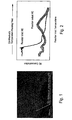
- Fig. 1 illustrates a zeolite material for use as an absorber which has a three-dimensional molecular cell structure
- Fig. 2 is a graph which shows hydrocarbon concentration at the outlet as the gas flow temperature rises when hydrocarbon fuel is passed through a reactor coated with a zeolite;
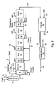
- Fig. 3 is a flow diagram showing one embodiment of the invention for reforming hydrocarbon fuel and treatment of the reformed material with a water shift reactor followed by zeolite treatment for introduction of reformed fuel into a fuel cell.
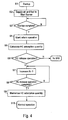
- Fig. 4 is a flowchart illustrating operation of the process of Fig. 3 from start-up to normal operation
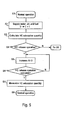
- Fig. 5 is a flowchart showing operation of the process of Fig. 3 during normal operation.
- Fig. 6 is a flow diagram of a second embodiment of the invention showing the operation of the fuel reformer with the hydrocarbon absorption function to provide fuel to the fuel cell.
- the present invention is concerned with operation of a fuel cell, and more particularly with improvements to fuel reformers which supply hydrogen to a fuel cell system.
- the combination of the fuel reformer with an absorber for absorbing hydrocarbon (HC) from the gas stream generated by the reformer with the subsequent release and burning of the hydrocarbon serves to substantially purify the mixture of gases recovered from the reformer prior to introduction of the gases into a fuel cell system, especially during operating temperatures lower than normal.
- the fuel cell purifying system of the present invention is particularly adapted for small scale operation and optimally serves as reforming system in a fuel cell generating device used in vehicles such as automobiles.
- a reformer In fuel cell systems, a reformer is provided which is effective to reform hydrocarbon fuels into a hydrogen rich fuel for introduction into the fuel cell.
- a reformer is combined with a shift reaction section to perform a water gas shift reaction for further conversion.
- the hydrogen rich gas emanating from the reformer is reacted with water to shift the carbon monoxide in the gas to hydrogen and carbon dioxide, and thereby increase hydrogen content of the hydrogen rich gas.
- the present invention provides a novel fuel reformer system, the combination of the fuel reformer system with a fuel cell and the methods for treating hydrocarbon fuels to substantially increase the hydrogen content in the gas stream and improve the efficiency of the fuel cell system.
- the absorbent of the present invention is particularly effective during warm-up of the reformer system when operating temperatures are lower. At these lower temperatures of below about 200°C., at startup and in initial reform operation, unconverted or unreformed fuel flows out of the reformer as unreacted hydrocarbon downstream of the reformer without being completely reformed because the ideal mix of fuel, air, and water cannot be obtained. Since there is a discrepancy between the target supply quantities of fuel, air, and water in the actual supply quantities, there is substantial unreacted hydrocarbon in the system. The out flowing hydrocarbon flows out of the system without being purified by oxidation, since the downstream reactor burner is not sufficiently warmed up. In reform operation, since there are amounts of outflow hydrocarbon, sufficient hydrocarbon conversation efficiency cannot be acquired in the early stages of the reformer operation.
- the present invention solves this startup problem by providing an absorber downstream of the reformer.
- the absorber functions to absorb unreacted hydrocarbon contained in the gases emanating from the reformer at the lower startup temperatures. Once the system reaches operating temperatures of above 200°C., the hydrocarbon gases are released by the absorber to the system. The released hydrocarbons are preferably further reacted with oxygen to produce additional hydrogen for introduction into the fuel cell.
- the absorption section is provided wherein an absorbent material is maintained which is suitable to absorb unreacted hydrocarbon from the fuel reforming system.
- the preferred absorber is a zeolite material.
- Fig. 1 illustrates a typical zeolite structure.
- Zeolites are well known and are generally hydrous aluminum-sodium silicates in the form of porous granules.
- the zeolites are also known as molecular sieves which contain pores in the Angstrom size.
- the preferred zeolite of the present invention has a three dimensional molecular structure of a size physically suitable to absorb hydrocarbon gases emanating from the reforming system.
- the zeolite is also durable when used in a fuel reforming system and is preferably provided as a coating in a honeycomb substrate reactor.
- the hydrocarbons from the reforming system are temporarily absorbed in the zeolitic molecular structure at low temperature and are subsequently released from the absorbent by thermal motion when the environment reaches an elevated or higher temperature.
- the absorbent such as a zeolite is a complex oxide containing silica and aluminum as its main constituents, and contains substantially no precious metals or transition material, no reaction of the gases of consequence occurs within the absorbent to affect the reform reaction.
- the hydrocarbon concentration at the outlet falls due to absorption at low temperature and the hydrocarbon is then released as the temperature rises.
- the outlet concentration of the hydrocarbon becomes higher than the inlet concentration due to the release of the hydrocarbon.
- the hydrocarbon recovered from the absorbent reactor is then purified by combustion using a burner located downstream of the absorbent material. This serves to substantially increase the hydrogen concentration in the gases for introduction into the fuel cell.
- Fig. 3 is a flow sheet illustrating operation of one embodiment of the reforming purifying system of this invention, including use of the absorber section.
- the system provides a reformer 10, a water shift reactor 20, the absorbent reactor 30 (HC Trap), fuel cell 40, and the anode burner 50.
- the fuel 1 from line 1 and air from line 2 are introduced into start burner 3 initiate the reaction.
- the fuel is principally gasoline, but as is well known in the art, other fuels can be reformed to form hydrogen gas in such reformer reactions.
- Typical fuels include gasoline, methanol, diesel, and naphtha, all of which are well known.
- Fuels are typically used which can be subjected to a reformer reaction to produce a mixture containing sufficient hydrogen to serve as fuel for a fuel cell.
- gases from the start burner 3 are introduced by line 4 into premixing chamber 5 of the reformer.
- additional fuel 2 gasoline
- Reformer 10 may be of any desired structure as is well known in the art. It is preferred that the reformer be provided with a reforming chamber which may or may not contain a catalyst as is well known to the art.
- the fuel such as gasoline is reformed to produce hydrogen rich gas by reaction at a high temperature of at least 650°C.
- the product from the reformer is a mixture of gases including a substantial amount of hydrogen as is known in the art.
- the reformer is the reactor that reforms the fuel primarily to carbon monoxide and hydrogen by addition of small quantities of oxygen, air and water to the fuel and causing the reaction to occur under high temperatures.
- Preferred operating temperatures in the reformer are above 650°C and preferably between 650°C and 900°C.
- the reformer may be either a catalytic reformer utilizing a metallic catalyst or a may be a non-catalytic reformer. At startup however, reformer temperatures will be substantially below the preferred operating temperature of 650°C, e.g., in the range of 150°C. to 650°C.
- the vapors produced by the reformer are then transferred to the water shift reactor to promote the shift reaction of carbon monoxide and water to carbon dioxide and hydrogen.
- the operating temperature for the water-shift reactor is in the range of 300°C to 500°C for the high temperature shift reactor (HTS) and 200°C to 350°C for the low temperature shift reactor (LTS).
- HTS is the high temperature shift 21
- LTS is the low temperature shift 22.
- Water 2 from line 23 is introduced into each of the high temperature shift reactor 21 and low temperature shift reactor 22 after vaporization at heaters 24 and 25, respectively.
- the mixture of gases leaving the low temperature reactor are then reduced in temperature by passing through heat exchanger 27 (HEX) in preparation for introduction into preferential oxidizer 29 (PrOx1). Air or oxygen (Air3) is then introduced to the oxidizer 29 by line 28.
- HEX heat exchanger 27
- Air or oxygen Air3
- the operating temperature in the preferential oxidizer is in the range of about 120 to180°C. for the reaction with oxygen which can be detected by temperature sensor 33.
- Hydrocarbon trap 30 is basically a reactor comprising a substrate containing zeolite material.
- the structure of this reactor may be of any desired type although a preferred reactor is a honeycomb structure containing a zeolite coating thereon.
- Any type of absorbent zeolite may be used, but the zeolite is preferably a three-dimensional mass structure having suitable cavities for absorption of the hydrocarbon and will function to absorb the hydrocarbon at a first temperature and release the hydrocarbon at a second temperature.
- a preferred first temperature for the zeolite absorbent is in the range of 100 to 150°C.
- a preferred second or desorption temperature is in the range of 200 to 300°C., preferably about 225-250°C.
- the structure of the zeolite absorbent is complex but is generally a three-dimensional mass structure which comprises holes or cavities and windows which connect the cavities. These cavities are sufficiently large for the zeolite of the invention to absorb a few hydrocarbon molecules although a large amount of diffusion resistance is produced as these absorbed molecules pass through the window portion. This resistance defines the hydrocarbon absorbency and desorption force of the zeolite.
- an MFI type zeolite has a structure of straight pores (0.51 x 0.55nm) and zigzag pores (0.54 x 0.56nm) which cross each other.
- the preferred zeolites for use in the invention are the MFI type zeolites and beta-type zeolites, all of which are well known in the art.
- Zeolites have sufficient durability to function as a fuel reforming material. Heat deterioration is a key issue with durability.
- Zeolites have the basic component molecules SiO 2 and Al 2 O 3 which are combined in a certain manner which form the zeolite structure. SiO 2 and Al 2 O 3 have a high heat resistance of at least 700°C.
- the zeolite structure has a base of SiO 2 but a small amount of Si is replaced with Al which thus provides higher durability against heat.
- the operation temperature for the absorption is at 300°C. or lower so that zeolite absorbent durability is excellent in this environment.
- the zeolite not exhibit any substantial reaction with the components of the fuel. It is known of course, that nobel metals or transition metals can be provided in zeolites as a catalytic material to promote fuel reformation and reaction, shift reactions and preferential oxidizer reactions. However, the zeolite used in the hydrocarbon trap in this invention should not contain any substantial amount of such catalytic metals or other catalysts.
- the MFI-type zeolite developed by Mobil Oil Corporation, is an alumina silica zeolite with a high silica and low aluminum content.
- This type of zeolite is also known as ZSM-5 zeolites. Its structure is based on channels with intersecting tunnels. The aluminum sites are very acidic. It has been discovered according to the present invention that utilization of a zeolite such as the ZSM type or beta type zeolites in general provide excellent advantages as absorbers in the hydrocarbon trap system of this invention.
- the gases in preferential oxidizer (PrOx) 29 are in the temperature range of about 120 to 180°C.
- hydrocarbon trap 30 which contains the absorbent
- unreacted hydrocarbon in the gases is absorbed into the zeolite absorbent during the startup phase at temperatures below about 200°C., usually about 100 to 150°C.
- the hydrocarbons are absorbed by the zeolite.
- the hydrocarbons are absorbed by the zeolite, usually at about 230-280°C. for the preferred zeolite absorbers.
- the hydrocarbons are absorbed in the zeolite at 30.
- the non-absorbed gases then pass through heat exchanger 31 and are introduced into the second preferential oxidizer 37 (PrOx2).
- air is introduced via line 33 (Air 4) to oxidize additional CO in the hydrogen-rich atmosphere.
- the gaseous stream from oxidizer 37 which is rich in hydrogen and low in unreacted hydrocarbons, is then passed by line 38 to fuel cell 40 where it is mixed with air from line 41 (Air 5) to power the fuel cell stack. Waste gases are removed from the fuel cell by line 42.
- the anode exhaust from fuel cell 40 is sent via line 43 to anode burner 50 where the gases are burned in the presence of air from line 44 (Air 6) and exhausted to the atmosphere at 45.
- the absorber will desorb the hydrocarbon from its pores for further conversion of the hydrocarbon in oxidizer 37 by reaction with oxygen. Additional hydrogen formed then further enriches the hydrogen gas fuel to fuel cell 40.
- the hydrocarbon will be desorbed from the zeolite at a temperature in the range of about 250°C. Obviously, this desorption temperature will vary depending on the pore and/or window size of the zeolite.
- the absorber or HC Trap 30 is provided with a temperature sensor 26 for such purposes. Since the hydrocarbon is usually desorbed at a temperature in the range of 200-280°C., it may need to be cooled by heat exchanger 31 for introduction into oxidizer 37 where the oxygen reaction is conducted at a temperature in the range of about 120° to 180°C.
- Fig. 4 The operation of the fuel reformer with the absorption function of Fig. 3 is illustrated in Fig. 4. As may be understood, this operation is computer controlled for optimum results in operation.
- start-up operation begins at S1 where fuel and air are supplied to the start burner 3 at S2.
- the start up is judged complete when the target temperature is reached as far as the anode burner.
- the start reform operation is then initiated at S4 at which time the supply of fuel 1 and air 1 is stopped and fuel 2, air 2-6 and water 1 and 2 are supplied in response to the operation request to initiate the reformer operation at 10.
- the hydrocarbon release quantity per start up is predetermined by experiment and the data entered.
- the hydrocarbon absorption quantity is calculated by adding the present hydrocarbon release quantity to the previously used hydrocarbon absorption quantity stored in memory.
- the supply of air 3 is increased (S7) thus causing oxygen and air to react with the hydrogen and carbon monoxide in the reformed gas, and raising the inlet temperature of the hydrocarbon absorption material to 250°C.
- the quantity of air supply increase is predetermined by experiment and the data entered.
- the necessary time for hydrocarbon release is judged by the computer.
- the necessary time for hydrocarbon release is predetermined by experiment in the lab and the lapse of a fixed time is measured.
- the released hydrocarbon is thereafter purified in the anode burner and the hydrocarbon absorption quantity is memorized as 0 at S9. The operation then shifts to normal operation at S10.
- Fig. 5 normal operation starts at S1 and at S2, fuel 2, air 2-6 and water 1 and 2 are supplied in response to operation request.
- counter T measures the elapsed time since normal operation of the system started, and advances the count by 1 per unit time. For example, if unit time is one second, counter T advances by 1 second.
- the quantity of hydrocarbon released per unit time in normal operation is predetermined by experiment and the data entered. The hydrocarbon absorption quantity is calculated based on the predetermined hydrocarbon absorption quantity and the time elapsed in normal operation as obtained from counter T, and is added to the previous hydrocarbon absorption quantity stored in memory.
- the supply of air 3 through line 28 is increased, thereby raising the inlet temperature of the hydrocarbon absorption material to 250°C.
- the quality of air supply increase is predetermined by experiment and stored in memory.
- the necessary time for hydrocarbon release is judged by the computer as in the present case, necessary time for hydrocarbon release is predetermined by experiment and lapse of fixed time is measured.
- the released hydrocarbon is purified in the anode burner.
- the hydrocarbon absorption quantity is memorized as 0 and at the same time, the counter time is memorized as 0 and normal operation is continued at S8.
- Fig. 6 provides an alternative operation of the invention and where like numerals in Fig. 6, make reference to the same elements in Fig. 5.
- the absorbent or hydrocarbon trap (HCTrap) is provided in the second oxidizer 37 (PrOx2) rather than preferential oxidizer 24 (PrOx1).
- additional hydrocarbon is converted to hydrogen and other gases in preferential oxidizer 24 as described for Figure 3 after which the gases are cooled in heat exchanger 31 and then passed to PrOx2 oxidizer 37 where the absorbent 30 (HC Trap) is located.
- hydrocarbon gases are trapped and stored in the zeolite absorbent contained in the HCTrap in oxidizer 37.
- gasoline is the hydrocarbon fuel and the hydrocarbon absorption reactor is provided downstream of the preferential oxidizer 1 as in Figure 3 to trap hydrocarbon generated due to the fact that at start up or during normal operation, the actual incoming quantities of fuel, air and water are different from the targeted supply quantities.
- the gasoline fuel is reformed in reactor 10 in the presence of oxygen to reform the fuel mainly to CO and H 2 by the addition of small quantities of oxygen and water to the fuel and cause a reaction at a high operating temperature, preferably above 650°C.
- the resulting mixture of gases is then subjected to the water-shift reaction to promote shift reaction of CO plus H 2 0 to ⁇ CO 2 plus H 2 .
- the operating temperature is 300°C to 500°C for the high temperature shift 21 and 200° to 350°C for the low temperature shift 22, as shown in Figure 3.
- the gases from the water shift reactor then passed through cooling heat exchanger 23 to preferential oxidizer 24 where the gases are mixed with air 3 from line 25.
- This oxidizer selectively oxidizes the CO that did not react in the water-shift reactor by using oxygen in hydrogen rich conditions.
- the operating temperature in this oxidizer is about 120° to 180°C.
- the warm up temperature of PrOx 2 oxidizer 37 is 150°C and the hydrocarbon absorption temperature of the zeolite is 230°C, hydrocarbon that is absorbed during warm up or normal operation is not released.
- the zeolite used in the absorber is an MFI type zeolite as described above in the form of a zeolite coating on a metal honeycomb substrate.
- Example 1 the operation is as in Example 1 except that the zeolite coating as the absorbent is contained in preferential oxidizer 37 so that this oxidizer also acts as a hydrocarbon absorption reactor, as described with respect to Example 1 for the first preferential oxidizer 24. Otherwise, the operation is the same as in Example 1.
- the present invention solves the problems in start up and reform operations when fuel flows out as hydrocarbon downstream to the reformer without being completely reformed because the ideal mix of fuel, air and water cannot be obtained in the startup phase.
- This invention solves the problem of the discrepancy between the target supply quantity of fuel, air and water and the actual supply of quantities of these reactants.
- the outflowing hydrocarbon flows out of the reformer system without being purified by oxidation since the downstream burner is not sufficiently warmed up. Further in the reform operation, since there are required balances of outflow of hydrocarbon, sufficient hydrocarbon conversion efficiency cannot be acquired.
- the present invention overcomes these problems.
Landscapes
- Chemical & Material Sciences (AREA)
- Chemical Kinetics & Catalysis (AREA)
- Engineering & Computer Science (AREA)
- Organic Chemistry (AREA)
- General Chemical & Material Sciences (AREA)
- Electrochemistry (AREA)
- Combustion & Propulsion (AREA)
- Inorganic Chemistry (AREA)
- Life Sciences & Earth Sciences (AREA)
- Manufacturing & Machinery (AREA)
- Sustainable Development (AREA)
- Sustainable Energy (AREA)
- Physics & Mathematics (AREA)
- Fluid Mechanics (AREA)
- Analytical Chemistry (AREA)
- Oil, Petroleum & Natural Gas (AREA)
- Health & Medical Sciences (AREA)
- General Health & Medical Sciences (AREA)
- Hydrogen, Water And Hydrids (AREA)
- Fuel Cell (AREA)
- Separation Of Gases By Adsorption (AREA)
- Solid-Sorbent Or Filter-Aiding Compositions (AREA)
Applications Claiming Priority (2)
| Application Number | Priority Date | Filing Date | Title |
|---|---|---|---|
| US10/458,625 US20040253493A1 (en) | 2003-06-11 | 2003-06-11 | Reformate purifying system for fuel processing systems |
| US458625 | 2003-06-11 |
Publications (1)
| Publication Number | Publication Date |
|---|---|
| EP1486253A1 true EP1486253A1 (fr) | 2004-12-15 |
Family
ID=33299647
Family Applications (1)
| Application Number | Title | Priority Date | Filing Date |
|---|---|---|---|
| EP04013642A Withdrawn EP1486253A1 (fr) | 2003-06-11 | 2004-06-09 | Appareillage de reformage avec un absorbant pour hydrocarbures |
Country Status (3)
| Country | Link |
|---|---|
| US (1) | US20040253493A1 (fr) |
| EP (1) | EP1486253A1 (fr) |
| JP (1) | JP2005050788A (fr) |
Cited By (2)
| Publication number | Priority date | Publication date | Assignee | Title |
|---|---|---|---|---|
| WO2007042278A1 (fr) * | 2005-10-13 | 2007-04-19 | Bayerische Motoren Werke Aktiengesellschaft | Systeme reformeur et procede de reformage |
| WO2007140848A1 (fr) * | 2006-06-03 | 2007-12-13 | Bayerische Motoren Werke Aktiengesellschaft | Procédé de fonctionnement pour un système constitué d'un reformeur et d'un dispositif de post-traitement catalytique des gaz d'échappement |
Families Citing this family (7)
| Publication number | Priority date | Publication date | Assignee | Title |
|---|---|---|---|---|
| DE102004053460A1 (de) * | 2004-11-05 | 2006-05-11 | Emitec Gesellschaft Für Emissionstechnologie Mbh | Schutzelement für einen Messfühler, sowie entsprechender Messfühler und Wabenkörper |
| US8101306B2 (en) * | 2005-08-02 | 2012-01-24 | Samsung Sdi Co., Ltd. | Fuel cell system with fuel reforming units |
| JP5006776B2 (ja) * | 2007-12-10 | 2012-08-22 | 本田技研工業株式会社 | 燃料改質装置 |
| WO2010109863A1 (fr) * | 2009-03-27 | 2010-09-30 | パナソニック株式会社 | Système de pile à combustible |
| EP2432061A4 (fr) * | 2009-05-12 | 2013-10-30 | Panasonic Corp | Système de pile à combustible |
| WO2010131447A1 (fr) * | 2009-05-12 | 2010-11-18 | パナソニック株式会社 | Système de pile à combustible |
| JP5869137B2 (ja) | 2011-10-14 | 2016-02-24 | サウジ アラビアン オイル カンパニー | 補助電源ユニット用途における水素化脱硫ユニットおよび固体酸化物形燃料電池システムの組み合わせへの送達のための非触媒水素発生プロセス |
Citations (5)
| Publication number | Priority date | Publication date | Assignee | Title |
|---|---|---|---|---|
| EP0270177A1 (fr) * | 1986-12-02 | 1988-06-08 | Shell Internationale Researchmaatschappij B.V. | Procédé et dispositif de conversion d'hydrocarbures |
| US5093102A (en) * | 1988-05-27 | 1992-03-03 | Institut Francais Du Petrole | Process for the production of high purity hydrogen by catalytic reforming of methanol |
| US20020040549A1 (en) * | 2000-10-06 | 2002-04-11 | Yasuo Kondo | Hydrogen supply device |
| US20030113257A1 (en) * | 2001-12-14 | 2003-06-19 | Hisashi Kobayashi | Method for producing hydrogen |
| DE10350318A1 (de) * | 2002-10-29 | 2004-05-27 | Toyota Jidosha Kabushiki Kaisha, Toyota | Gerät zur Brennstoffreformierung und Brennstoffzellensystem |
Family Cites Families (12)
| Publication number | Priority date | Publication date | Assignee | Title |
|---|---|---|---|---|
| US3441393A (en) * | 1966-01-19 | 1969-04-29 | Pullman Inc | Process for the production of hydrogen-rich gas |
| JPS51138223A (en) * | 1975-05-27 | 1976-11-29 | Nissan Motor Co Ltd | Gas generator |
| US4495154A (en) * | 1982-05-28 | 1985-01-22 | Energy Research Corporation | Fuel reformer |
| US5043232A (en) * | 1990-05-10 | 1991-08-27 | International Fuel Cells Corporation | Fuel Preheating for a fuel processing system of a fuel cell power plant |
| JPH0869808A (ja) * | 1994-08-30 | 1996-03-12 | Toyota Motor Corp | 改質装置と燃料電池システム |
| US6282902B1 (en) * | 1997-10-28 | 2001-09-04 | Hitachi, Ltd. | Waste processing system and fuel reformer used in the waste processing system |
| JP2000203804A (ja) * | 1999-01-14 | 2000-07-25 | Toyota Motor Corp | 燃料改質装置および燃料改質方法 |
| JP2001295707A (ja) * | 1999-06-03 | 2001-10-26 | Toyota Motor Corp | 車両搭載用の燃料改質装置 |
| US6210157B1 (en) * | 2000-04-07 | 2001-04-03 | Praxair Technology, Inc. | Fuel reformer combustion process |
| US6329091B1 (en) * | 2000-04-14 | 2001-12-11 | Ford Global Technologies, Inc. | Fuel reformer system for a fuel cell |
| US6541142B1 (en) * | 2000-10-04 | 2003-04-01 | General Motors Corporation | Fuel cell system having a methanol decomposition reactor |
| US6833126B2 (en) * | 2001-03-30 | 2004-12-21 | Industries Co., Ltd. | Method and apparatus for reforming fuel |
-
2003
- 2003-06-11 US US10/458,625 patent/US20040253493A1/en not_active Abandoned
-
2004
- 2004-06-09 EP EP04013642A patent/EP1486253A1/fr not_active Withdrawn
- 2004-06-10 JP JP2004172116A patent/JP2005050788A/ja not_active Abandoned
Patent Citations (5)
| Publication number | Priority date | Publication date | Assignee | Title |
|---|---|---|---|---|
| EP0270177A1 (fr) * | 1986-12-02 | 1988-06-08 | Shell Internationale Researchmaatschappij B.V. | Procédé et dispositif de conversion d'hydrocarbures |
| US5093102A (en) * | 1988-05-27 | 1992-03-03 | Institut Francais Du Petrole | Process for the production of high purity hydrogen by catalytic reforming of methanol |
| US20020040549A1 (en) * | 2000-10-06 | 2002-04-11 | Yasuo Kondo | Hydrogen supply device |
| US20030113257A1 (en) * | 2001-12-14 | 2003-06-19 | Hisashi Kobayashi | Method for producing hydrogen |
| DE10350318A1 (de) * | 2002-10-29 | 2004-05-27 | Toyota Jidosha Kabushiki Kaisha, Toyota | Gerät zur Brennstoffreformierung und Brennstoffzellensystem |
Cited By (3)
| Publication number | Priority date | Publication date | Assignee | Title |
|---|---|---|---|---|
| WO2007042278A1 (fr) * | 2005-10-13 | 2007-04-19 | Bayerische Motoren Werke Aktiengesellschaft | Systeme reformeur et procede de reformage |
| WO2007140848A1 (fr) * | 2006-06-03 | 2007-12-13 | Bayerische Motoren Werke Aktiengesellschaft | Procédé de fonctionnement pour un système constitué d'un reformeur et d'un dispositif de post-traitement catalytique des gaz d'échappement |
| US8015803B2 (en) | 2006-06-03 | 2011-09-13 | Bayerische Motoren Werke Aktiengellschaft | Operating method for a system composed of a reformer and a catalytic exhaust gas aftertreatment device |
Also Published As
| Publication number | Publication date |
|---|---|
| JP2005050788A (ja) | 2005-02-24 |
| US20040253493A1 (en) | 2004-12-16 |
Similar Documents
| Publication | Publication Date | Title |
|---|---|---|
| JP3890020B2 (ja) | 水吸着を用いる燃料プロセッサの迅速な始動 | |
| JP4714691B2 (ja) | 温度揺動式改質および固体酸化物燃料電池を使用した電気製造方法 | |
| US6562088B2 (en) | Method for operating a hydrogen generating apparatus | |
| CN1863730B (zh) | 用于燃料电池系统的变压转化 | |
| US7226490B2 (en) | Fuel processor for producing a hydrogen rich gas | |
| KR100801861B1 (ko) | 탄화수소의 자기발열 접촉 증기 개질법 | |
| US6869580B2 (en) | Pyrolysis-based fuel processing method and apparatus | |
| US20060183009A1 (en) | Fuel cell fuel processor with hydrogen buffering | |
| EP1231663A1 (fr) | Methode et dispositif pour la purification de gaz dans des dispositifs de transformation d'énérgie | |
| JP2004536006A (ja) | 単一チャンバーのコンパクトな燃料処理装置 | |
| US7247258B2 (en) | Compact partial oxidation reactor assemblage with fast start-up capability | |
| CA2672208A1 (fr) | Chambre de combustion hybride pour application de conversion des combustibles | |
| CA2671466A1 (fr) | Procedes d'utilisation d'un pre-bruleur catalytique dans des applications de traitement de combustible | |
| US20040005268A1 (en) | Method and multi-stage shift reactor for reducing the carbon monoxide content in a hydrogen-containing gas stream, and reformer installation | |
| CN1989068A (zh) | 重整燃料的方法和设备 | |
| EP1486253A1 (fr) | Appareillage de reformage avec un absorbant pour hydrocarbures | |
| EP1468722A2 (fr) | Système et procédé pour la réduction des émissions des moteurs | |
| US20060168887A1 (en) | Method for producing a fuel gas containing hydrogen for electrochemical cells and associated device | |
| US7435275B2 (en) | System and method of heating an exhaust treatment device | |
| JP3916485B2 (ja) | 水素含有ガス生成装置の前処理方法 | |
| US20020001740A1 (en) | Method for improving the light-off performance of mobile fuel cell systems | |
| JP2003048702A (ja) | 改質ガス中の一酸化炭素を低減する一酸化炭素除去装置 | |
| Pfefferle | A Compact, Lightweight, Fast-Response Preferential Oxidation Reactor for PEM Automotive Fuel Cell Applications. | |
| JP2003026401A (ja) | 水素精製装置 |
Legal Events
| Date | Code | Title | Description |
|---|---|---|---|
| PUAI | Public reference made under article 153(3) epc to a published international application that has entered the european phase |
Free format text: ORIGINAL CODE: 0009012 |
|
| 17P | Request for examination filed |
Effective date: 20040609 |
|
| AK | Designated contracting states |
Kind code of ref document: A1 Designated state(s): AT BE BG CH CY CZ DE DK EE ES FI FR GB GR HU IE IT LI LU MC NL PL PT RO SE SI SK TR |
|
| AX | Request for extension of the european patent |
Extension state: AL HR LT LV MK |
|
| AKX | Designation fees paid |
Designated state(s): DE FR GB |
|
| 17Q | First examination report despatched |
Effective date: 20071130 |
|
| RAP1 | Party data changed (applicant data changed or rights of an application transferred) |
Owner name: NISSAN MOTOR CO., LTD. |
|
| STAA | Information on the status of an ep patent application or granted ep patent |
Free format text: STATUS: THE APPLICATION IS DEEMED TO BE WITHDRAWN |
|
| 18D | Application deemed to be withdrawn |
Effective date: 20100105 |