EP1486258A2 - Système de fixation de réservoirs jetables pour pulvérisateur alimenté par gravité - Google Patents
Système de fixation de réservoirs jetables pour pulvérisateur alimenté par gravité Download PDFInfo
- Publication number
- EP1486258A2 EP1486258A2 EP04009885A EP04009885A EP1486258A2 EP 1486258 A2 EP1486258 A2 EP 1486258A2 EP 04009885 A EP04009885 A EP 04009885A EP 04009885 A EP04009885 A EP 04009885A EP 1486258 A2 EP1486258 A2 EP 1486258A2
- Authority
- EP
- European Patent Office
- Prior art keywords
- container
- liner
- fluid
- paint
- walled
- Prior art date
- Legal status (The legal status is an assumption and is not a legal conclusion. Google has not performed a legal analysis and makes no representation as to the accuracy of the status listed.)
- Withdrawn
Links
- 239000003973 paint Substances 0.000 title description 107
- 239000012530 fluid Substances 0.000 claims abstract description 100
- 238000000034 method Methods 0.000 claims abstract description 33
- 238000000465 moulding Methods 0.000 claims abstract description 15
- 238000011068 loading method Methods 0.000 claims abstract description 12
- 238000004519 manufacturing process Methods 0.000 claims abstract description 8
- 238000010102 injection blow moulding Methods 0.000 claims description 6
- 238000005507 spraying Methods 0.000 claims description 4
- 239000012528 membrane Substances 0.000 claims description 3
- 238000000071 blow moulding Methods 0.000 claims 2
- 230000005484 gravity Effects 0.000 description 9
- 238000003860 storage Methods 0.000 description 9
- 239000000463 material Substances 0.000 description 8
- XLYOFNOQVPJJNP-UHFFFAOYSA-N water Substances O XLYOFNOQVPJJNP-UHFFFAOYSA-N 0.000 description 5
- 238000011109 contamination Methods 0.000 description 4
- -1 polyethylene Polymers 0.000 description 4
- 239000002904 solvent Substances 0.000 description 4
- 238000002347 injection Methods 0.000 description 3
- 239000007924 injection Substances 0.000 description 3
- 238000010422 painting Methods 0.000 description 3
- 239000004033 plastic Substances 0.000 description 3
- 229920003023 plastic Polymers 0.000 description 3
- 239000004698 Polyethylene Substances 0.000 description 2
- 239000004743 Polypropylene Substances 0.000 description 2
- 239000000654 additive Substances 0.000 description 2
- 239000000853 adhesive Substances 0.000 description 2
- 230000001070 adhesive effect Effects 0.000 description 2
- 238000004140 cleaning Methods 0.000 description 2
- 239000012535 impurity Substances 0.000 description 2
- 229920001684 low density polyethylene Polymers 0.000 description 2
- 239000004702 low-density polyethylene Substances 0.000 description 2
- 229920000573 polyethylene Polymers 0.000 description 2
- 229920001155 polypropylene Polymers 0.000 description 2
- 239000000243 solution Substances 0.000 description 2
- 239000007921 spray Substances 0.000 description 2
- 230000000712 assembly Effects 0.000 description 1
- 238000000429 assembly Methods 0.000 description 1
- 238000000889 atomisation Methods 0.000 description 1
- 235000013361 beverage Nutrition 0.000 description 1
- 230000015572 biosynthetic process Effects 0.000 description 1
- 235000013409 condiments Nutrition 0.000 description 1
- 238000010276 construction Methods 0.000 description 1
- 230000001419 dependent effect Effects 0.000 description 1
- 238000009792 diffusion process Methods 0.000 description 1
- 238000002845 discoloration Methods 0.000 description 1
- 238000006073 displacement reaction Methods 0.000 description 1
- 238000001035 drying Methods 0.000 description 1
- 239000000428 dust Substances 0.000 description 1
- 239000000839 emulsion Substances 0.000 description 1
- 238000001125 extrusion Methods 0.000 description 1
- 230000009969 flowable effect Effects 0.000 description 1
- 235000013305 food Nutrition 0.000 description 1
- 235000003642 hunger Nutrition 0.000 description 1
- 229930195733 hydrocarbon Natural products 0.000 description 1
- 150000002430 hydrocarbons Chemical class 0.000 description 1
- 238000001746 injection moulding Methods 0.000 description 1
- 238000009434 installation Methods 0.000 description 1
- 235000008960 ketchup Nutrition 0.000 description 1
- 239000007788 liquid Substances 0.000 description 1
- 238000002156 mixing Methods 0.000 description 1
- 239000002991 molded plastic Substances 0.000 description 1
- 239000003348 petrochemical agent Substances 0.000 description 1
- 230000002028 premature Effects 0.000 description 1
- 238000001175 rotational moulding Methods 0.000 description 1
- 230000037351 starvation Effects 0.000 description 1
- 239000000758 substrate Substances 0.000 description 1
Images


Classifications
-
- B—PERFORMING OPERATIONS; TRANSPORTING
- B05—SPRAYING OR ATOMISING IN GENERAL; APPLYING FLUENT MATERIALS TO SURFACES, IN GENERAL
- B05B—SPRAYING APPARATUS; ATOMISING APPARATUS; NOZZLES
- B05B7/00—Spraying apparatus for discharge of liquids or other fluent materials from two or more sources, e.g. of liquid and air, of powder and gas
- B05B7/24—Spraying apparatus for discharge of liquids or other fluent materials from two or more sources, e.g. of liquid and air, of powder and gas with means, e.g. a container, for supplying liquid or other fluent material to a discharge device
- B05B7/2402—Apparatus to be carried on or by a person, e.g. by hand; Apparatus comprising containers fixed to the discharge device
- B05B7/2478—Gun with a container which, in normal use, is located above the gun
-
- B—PERFORMING OPERATIONS; TRANSPORTING
- B05—SPRAYING OR ATOMISING IN GENERAL; APPLYING FLUENT MATERIALS TO SURFACES, IN GENERAL
- B05B—SPRAYING APPARATUS; ATOMISING APPARATUS; NOZZLES
- B05B7/00—Spraying apparatus for discharge of liquids or other fluent materials from two or more sources, e.g. of liquid and air, of powder and gas
- B05B7/24—Spraying apparatus for discharge of liquids or other fluent materials from two or more sources, e.g. of liquid and air, of powder and gas with means, e.g. a container, for supplying liquid or other fluent material to a discharge device
- B05B7/2402—Apparatus to be carried on or by a person, e.g. by hand; Apparatus comprising containers fixed to the discharge device
- B05B7/2405—Apparatus to be carried on or by a person, e.g. by hand; Apparatus comprising containers fixed to the discharge device using an atomising fluid as carrying fluid for feeding, e.g. by suction or pressure, a carried liquid from the container to the nozzle
- B05B7/2408—Apparatus to be carried on or by a person, e.g. by hand; Apparatus comprising containers fixed to the discharge device using an atomising fluid as carrying fluid for feeding, e.g. by suction or pressure, a carried liquid from the container to the nozzle characterised by the container or its attachment means to the spray apparatus
-
- B—PERFORMING OPERATIONS; TRANSPORTING
- B05—SPRAYING OR ATOMISING IN GENERAL; APPLYING FLUENT MATERIALS TO SURFACES, IN GENERAL
- B05B—SPRAYING APPARATUS; ATOMISING APPARATUS; NOZZLES
- B05B7/00—Spraying apparatus for discharge of liquids or other fluent materials from two or more sources, e.g. of liquid and air, of powder and gas
- B05B7/24—Spraying apparatus for discharge of liquids or other fluent materials from two or more sources, e.g. of liquid and air, of powder and gas with means, e.g. a container, for supplying liquid or other fluent material to a discharge device
- B05B7/2402—Apparatus to be carried on or by a person, e.g. by hand; Apparatus comprising containers fixed to the discharge device
- B05B7/2481—Apparatus to be carried on or by a person, e.g. by hand; Apparatus comprising containers fixed to the discharge device with a flexible container for liquid or other fluent material
-
- B—PERFORMING OPERATIONS; TRANSPORTING
- B05—SPRAYING OR ATOMISING IN GENERAL; APPLYING FLUENT MATERIALS TO SURFACES, IN GENERAL
- B05B—SPRAYING APPARATUS; ATOMISING APPARATUS; NOZZLES
- B05B11/00—Single-unit hand-held apparatus in which flow of contents is produced by the muscular force of the operator at the moment of use
- B05B11/01—Single-unit hand-held apparatus in which flow of contents is produced by the muscular force of the operator at the moment of use characterised by the means producing the flow
- B05B11/02—Membranes or pistons acting on the contents inside the container, e.g. follower pistons
- B05B11/026—Membranes separating the content remaining in the container from the atmospheric air to compensate underpressure inside the container
- B05B11/027—Membranes separating the content remaining in the container from the atmospheric air to compensate underpressure inside the container inverted during outflow of content
-
- Y—GENERAL TAGGING OF NEW TECHNOLOGICAL DEVELOPMENTS; GENERAL TAGGING OF CROSS-SECTIONAL TECHNOLOGIES SPANNING OVER SEVERAL SECTIONS OF THE IPC; TECHNICAL SUBJECTS COVERED BY FORMER USPC CROSS-REFERENCE ART COLLECTIONS [XRACs] AND DIGESTS
- Y10—TECHNICAL SUBJECTS COVERED BY FORMER USPC
- Y10S—TECHNICAL SUBJECTS COVERED BY FORMER USPC CROSS-REFERENCE ART COLLECTIONS [XRACs] AND DIGESTS
- Y10S239/00—Fluid sprinkling, spraying, and diffusing
- Y10S239/14—Paint sprayers
Definitions
- the present invention is directed to a fluid supply cup for a fluid applicator, more particularly to a paint supply cup for a paint sprayer.
- Fluid is typically delivered to fluid applicators, such as paint sprayers, in one of three ways.
- the fluid may be fed through a hose connected to a remote pressurized source.
- the fluid is generally placed in a cup attached to the sprayer.
- the cup is suspended below a front end of a body on the sprayer and the fluid is fed to a nozzle by suction or aspiration induced by atomization air flow through the sprayer.
- This type of sprayer is commonly referred to as a suction feed sprayer.
- the cup may be pressurized to increase the fluid application rate.
- a cup is sometimes mounted above the sprayer body to feed the fluid via gravity to the sprayer so that less air pressure is needed to aspirate the paint, usually referred to as a gravity feed sprayer.
- Disposable cups and liners have been developed to avoid contamination between batches and to minimize the amount of cleaning needed between applications.
- U.S. Patent 5,816,501 to LoPresti et al. teaches a disposable collapsible liner for a suction feed sprayer, wherein the liner is within a paint jar and paint is drawn through a feed tube. However, the liner is subject to being drawn into the tube opening via suction, which can block the flow of paint through the tube.
- U.S. Patent 5,582,350 to Kosmyna et al. teaches a non-disposable gravity feed paint cup with a disposable liner.
- the liner requires the installation of a port with a special tool and takes considerable time and effort. Further, the liner is hard to remove without spilling paint into the paint cup, which requires cleaning of the cup.
- a novel fluid supply cup comprises a flexible liner integral with a container having an opening and a vent.
- a novel method of manufacturing a lined container includes the steps of molding a container having a vented mick-walled portion and an integral flexible thin-walled liner, and folding the thin-walled liner into the thick-walled portion.
- an improved method of applying a fluid comprises the steps of providing a flexible liner integral with a container having an opening and a vent, loading fluid into the liner, engaging the container with a fluid applicator, flowing the fluid out of the liner and into the fluid applicator, collapsing the liner, and flowing the fluid out of the fluid applicator.
- the fluid applicator is a sprayer
- the flowing step comprises spraying the fluid out of the sprayer.
- a fluid supply cup 10 is shown for feeding fluid to a fluid applicator 2.
- the novel fluid supply cup 10 includes a flexible liner 14 integral with a container 12 having an opening 16 (best shown in FIG. 2) and a vent 18.
- fluid supply cup 10 is for feeding fluid to a sprayer.
- fluid supply cup 10 is a paint cup for feeding paint to a paint sprayer 2; therefore the present invention will be described for a paint sprayer, such as a gravity feed paint sprayer for use in applying paint 1 to coat substrate surfaces.
- paint sprayer 2 is used in the automotive refinishing market, such as automobile body shops, for repainting automobiles. Paint cup 10 of the present invention is easy for an operator to install and is inexpensive to manufacture, saving the operators both time and money.
- fluid supply cup 10 is described herein as a paint cup, it alternatively can be used for supplying other flowable fluids, such as beverages, foods, or condiments, for example ketchup, gasoline, petrochemicals and hydrocarbons, water, water-based solutions, solvent-based solutions, emulsions, and adhesives.
- the fluid being supplied must be compatible with fluid supply cup 10 and should be applied in a similar manner as paint from paint cup 10.
- a paint sprayer 2 is shown in FIG. 1 and includes a body 3, a nozzle assembly 4 secured to a front end 5 of body 3, and a handle 6 depending from a rear end 7 of body 3.
- a trigger 8 is pivotally secured to body 3 for the manual actuation of sprayer 2.
- a top mounted, gravity feed paint cup 10 is mounted to body 3 via an adapter 22 near front end 5 for feeding paint to nozzle assembly 4.
- An air connector 9 is connected to an air hose (not shown) for the delivery of pressurized air to nozzle assembly 4, wherein the delivery of pressurized air is controlled by trigger 8.
- Compressed air from connector 9 is delivered through an internal passage (not shown) to nozzle assembly 4 and the compressed air acts to atomize paint and deliver it through nozzle assembly 4 to spray paint 1 about a spray axis 11. Paint 1 is delivered to nozzle assembly 4 via gravity from paint cup 10. The level of paint 1 in paint cup 10 must be higher than the sprayer connection channel 13, or else paint 1 will not feed via gravity to the nozzle assembly 4, a condition known as starvation.
- Novel paint cup 10 of the present invention provides an inexpensive, easy to use disposable container for the delivery of paint 1 to sprayer 2.
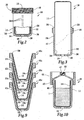
- Novel paint cup 10 includes a container 12 having an opening 16, best seen in FIG. 2, a,vent 18, and a flexible liner 14 integral with container 12.
- liner 14 is integrally formed with container 12 at joint 20 near opening 16. Paint 1 is loaded into liner 14 and container 12 is engaged with sprayer 2 so that the paint 1 can be fed to nozzle assembly 4.
- container 12 includes a generally cylindrical side wall 24 having a generally open first end 26 defining opening 16 into container 12 and a base wall 30 at a second end 28, wherein side wall 24 and base wall 30 surround an interior 32 of container 12.
- Side wall 24 includes a side interior surface 34 and base wall 30 includes a base interior surface 36.
- vent 18 is included generally at second end 28, such as in base wall 30, shown in FIG. 2. Vent 18 allows air to flow into the interior 32 of container 12, providing vacuum relief so that liner 14 may collapse (described below).
- side wall 24c of container 12c is generally frusto-conical in shape so that side wall 24c is slanted slightly, as shown in FIG. 9, so that a plurality of paint cups 10c can be stacked for easy storage and dispensation.
- the walls of container 12, such as walls 24 and 30, are relatively thick in relation to flexible liner 14. Walls 24, 30 should be thick enough so that container is generally stiff and rigid and will not easily collapse. In one embodiment, the thickness of walls 24, 30 is between about 0.02 inches and about 0.06 inches, preferably about 0.025 inches. The thickness of walls 24, 30 may be dependent on the material of construction of container 12.
- Side wall 24 can include graduations 38 indicating the level of paint 1 in paint cup 10.
- Graduations 38 can act as proportional indicators to indicate the levels of one or more fluids that should be added to paint cup 10 to provide a predetermined ratio between the liquids. For example, a certain amount of a'base paint color can be mixed with tinting additives at a predetermined ratio to match a desired color for an automobile.
- Container 12 also includes a means for connection to sprayer 2.
- the means for connection is threading 40 at first end 26 which engages directly with adapter 22 via adapter threading 42 so that paint cup 10 is releasably engageable with sprayer 2.
- the means for connection could also be a bayonet connection (not shown), or a snap engagement (not shown) between container 12 and adapter 22.
- the connection between container 12 and adapter 22b can be via a lid 44, see FIG. 8, wherein container 12 can be connected to lid 44 with threading 40 engaging with lid threading 45, and lid 44 can be connected to adapter 22b via threading 46.
- Container 12 can engage with lid 44 and lid 44 can engage with adapter 22b by other connection means than a threaded connection, such as a bayonet connection, a snap engagement, or a self-locking taper engagement between the inlet connection and the container (not shown).
- a threaded connection such as a bayonet connection, a snap engagement, or a self-locking taper engagement between the inlet connection and the container (not shown).
- Novel self-locking tapered connections are described in more detail in the commonly assigned, co-pending patent application with Attorney Docket # 14115 filed contemporaneously herewith, the disclosure of which is incorporated herein by reference.
- lid 44 keeps paint cup 10 sealed until lid 44 is engaged with adapter 22.
- lid 44 includes a perforable membrane 47 which is broken when adapter 22 is engaged with lid 44, shown in FIG. 8. After container 12 has been engaged with lid 44, paint 1 is sealed within paint cup 10 because air, water vapor, and other materials cannot pass through membrane 47.
- the means for connection create a tight hermetic seal between container 12 and adapter 22 or between container 12 and lid 44 and between lid 44 and adapter 22 so that paint cup 10 is water tight and air tight during operation of sprayer 2 to prevent the escape of solvents, causing premature drying of paint 1 and the formation of a skin layer. Also, water can degrade the quality of paint 1, causing contamination or discoloration of the paint.
- container 12 can have an interior volume of between about 8 fluid ounces and about 2.5 gallons, preferably between about 16 fluid ounces and about one liter.
- a one liter generally cylindrical container 12 has a length of about 4 inches and a diameter of about 6 inches.
- container 12 can have different proportions or geometry.
- the size and shape of container 12 is conducive to the automobile refinishing industry so that sprayer 2 and paint cup 10 are not unwieldy or overly heavy for an operator to handle.
- container 12 is made from a translucent material so that the level of paint 1 can be seen through container 12.
- Container 12 should also be relatively durable and resistant to collapsing, be made from a relatively inexpensive material and be inexpensive to manufacture so that container 12 can be disposable, and be made from a material that is substantially unreactive, preferably unreactive to the fluid in fluid supply cup 10.
- container 12 is made from a molded plastic, such as polyethylene or polypropylene.
- container 12 is molded from low-density polyethylene.
- flexible liner 14 is located within interior 32 of container 12.
- Liner 14 is thin and flexible so that it is capable of collapsing as paint 1 flows out of paint cup 10 and into sprayer 2 while still preventing the inflow of air into liner 14.
- a partial vacuum is formed within liner 14 due to fluid displacement.
- liner 14 is flexible and vent 18 allows air to flow into interior 32 of container, atmospheric pressure offsets the vacuum formed in liner 14, and causes liner 14 to collapse, as shown in FIG. 5.
- the thickness of liner 14 is relatively thinner than the thickness of walls 24, 30 of container 12. Liner 14 should be thin enough so that it is flexible, softer than container 12, pliable, and insertable into interior 32 of container 12. In one embodiment, the thickness of liner 14 is between about 0.004 inches and about 0.015 inches, and preferably between about 0.005 inches and about 0.01 inches.
- Flexible liner 14 is integral with container 12.
- liner 14 is integrally molded with container 12 so that they are formed continuously, best shown in FIG. 2, such as by injection blow molding flexible liner 14 and container 12 in the same process as described below.
- liner 14 is integral with container 12 at joint 20 at first end 26 around opening 16, as shown in FIGS. 2 and 3, so that liner 14 will be easily invertable into interior 32 of container 12.
- liner 14b and container 12b are molded or formed separately and adhered to each other to form paint cup 10b.
- Liner 14b can be adhered or attached to container 12b via, for example, adhesives, plastic weldment, sonic weldment, molecular diffusion, or other methods of fusing plastic.
- liner 14b is adhered to container 12b at joint 20b near opening 16b.
- liner 14b includes a portion 48 that extends past opening 16b to cover threading 40b so that when container 12b is threadingly engaged with adapter 22, so that portion 48 of liner 14b will act as an extra seal between container 12b and adapter 22 to prevent leakage of paint 1.
- liner 14 substantially conforms to interior surfaces 34, 36 of container 12 when liner 14 is not collapsed, still more preferably so that there is full geometric conformity between interior surfaces 34, 36 and liner 14. Conformity of liner 14 preferred so that the level of paint 1 in liner 14 can most accurately be measured with graduations 38. Accurate indication of fluid level is particularly important during mixing of multiple fluids in predetermined ratios.
- flexible liner 14 is preferably made from a translucent material so that the paint level can be seen.
- Liner should also be made from a material that can be pliable and foldable, and that is unreactive with the fluid in fluid supply cup 10. Further, the material of liner 14 should be inexpensive, and liner 14 should be inexpensive to manufacture.
- liner 14 is made from a moldable plastic, such as polyethylene or polypropylene. In a preferred embodiment, liner 14 is molded from low density polyethylene.
- paint cup 10 in order to connect paint cup 10 with sprayer 2, the operator simply has to engage container 12 with adapter 22, or with lid 44 and then engage lid 44 with adapter 22b as in FIG. 8, which requires very little time or effort on the part of the operator.
- the easy assembly of paint cup 10 offers a significant savings of time and effort on the part of operators over traditional paint cups, which require significant assembly of several complicated parts.
- paint cup 10 is inexpensive to manufacture so that it can be disposable without being overly expensive.
- adapter 22 provides a connection between paint cup 10 and sprayer 2 and provides a path for paint 1 to flow from paint cup 10 into sprayer body 3.
- Adapter 22 can engage directly with container 12 at opening 16, such as between container threading 40 and adapter threading 42, or adapter 22 can engage with a lid 44.
- adapter 22 is a mass produced machined adapter and the connection between adapter 22 and sprayer body 3 is a conventional connection, such as threaded engagement between threading 49 on adapter 22 and sprayer threading 50, so that adapter may be releasably connected to several sprayers 2.
- adapter also includes a filter (not shown) to filter impurities, such as dust or other particulates, from flowing into sprayer 2 so that the impurities will not be applied to the surface being painted.
- adapter 22 is shown as being one piece, it is envisioned that adapter 22 can have other configurations, such as an adjustable adapter that allows the orientation of container 12 to be changed to ensure that paint 1 will flow into sprayer 2.
- a novel adjustable adapter is disclosed in the commonly assigned, co-pending patent application with Attorney Docket #14114 filed contemporaneously herewith, the disclosure of which is incorporated herein by reference.
- a storage lid 52 is provided for covering paint cup 10 when painting is completed or temporarily stopped.
- the exact amount of paint 1 required may not be easy to determine, and there is frequently left over paint 1.
- storage lid 52 includes a means for connection to container, such as storage lid threading 54 that engages with container threading 40, to cover opening 16 and provide a tight, hermetic seal with paint cup 10, so that left over paint 1 can be stored easily.
- Some paints 1 have a shelf life of up to about 3 days or more.
- the top 56 of storage lid 52 generally complements the base wall 30 of container 12 so that multiple covered paint cups 10 can be stacked.
- New and improved paint cup 10 is made by a novel method including the steps of molding a container, such as paint cup 10 shown in FIG. 2, having a vented thick-walled portion and an integral flexible thin-walled liner, and folding the thin-walled liner into the thick-walled portion.
- a container such as paint cup 10 shown in FIG. 2
- the thick-walled portion is container 12
- the thin-walled liner is flexible liner 14.
- Molding of liner 14 and container 12 are preferably done by a process wherein liner 14 and container 12 are integrally formed so that liner 14 and container 12 are molded as a single piece.
- the molding process forms a generally closed container, such as the generally closed cylinder shown in FIG. 3, wherein the thickness of the walls of the cylinder abruptly diminishes along the length of the cylinder between thin-walled liner 14 and thick-walled container 12.
- molding of liner 14 and container 12 comprises a two-step injection blow molding process.
- the two-step process requires precision control of a parison used to mold both liner 14 and container 12.
- Liner 14 injection molded in a first step at a relatively low pressure, wherein the temperature, pressure, and other molding conditions should be tightly controlled. After injection blow molding of liner 14, the pressure is increased to a relatively high pressure, to injection blow mold container 12.
- Injection blow molding of liner 14 and container 12 is accomplished through a blow hole formed at the base of container 12.
- hole 18 acts as the'blow hole during the molding process.
- the same hole 18 can be used to vent air into the interior 32 of container 12 during subsequent use of paint cup 10.
- Liner 14 and container 12 can be molded by other means, such as injection molding, rotational molding, suction molding, or extrusion molding. Injection blow molding is preferred because it is an inexpensive process. Alternatively, molding of liner 14 and container 12 can be separate and liner and container 12 can be made integral by adhering liner 14 to container.
- liner 14 is folded into container 12 to form a lined paint cup 10, shown in FIG. 2.
- Folding of liner 14 into container 12 can be done mechanically, such as by air pressure, applied to liner 14 to force it into the interior 32 of container 12, or by forming a partial vacuum in interior 32 of container 12 so that liner 14 is drawn into container 12.
- liner 14 is mechanically inserted into container 12 with assistance from a partial vacuum formed in interior 32 through vent 18.
- folding liner 14 in container 12 includes substantially conforming liner 14 to interior surfaces 34, 36 of container 12.
- conforming liner 14 to surfaces 34, 36 is accomplished by applying air pressure to liner 14 so that there is full geometric conformity between liner 14 and interior surfaces 34,36.
- a novel method of applying a fluid comprises the steps of providing a flexible liner 14 integral with a container 12 having an opening 16 and a vent 18, loading fluid, such as paint 1, into liner 14, engaging container 12 with a fluid applicator, flowing the fluid out of liner 14 and into the fluid applicator 2, collapsing liner 14, and flowing the fluid out of the fluid applicator.
- the flowing step comprises spraying the fluid out of sprayer 2 and in another method, sprayer 2 is a paint sprayer for spraying paint 1 onto a surface, such as the body of an automobile.
- the loading step includes loading paint into paint cup 10.
- the loading step can also comprise loading paint into liner 14 followed by loading a second fluid, such as another paint, tinting additives, or solvents, in predetermined ratios to create paint having a desired color.
- a second fluid such as another paint, tinting additives, or solvents
- the step of engaging container 12 with sprayer 2 can be accomplished by engaging container 12 directly with an adapter 22 connected to sprayer 2, shown in FIGS. 1 and 4, or by engaging container 12 with a lid 44 followed by engaging lid 44 with adapter 22b, as shown in FIG. 8.
- the collapsing step includes collapsing liner 14 due to a partial vacuum formed as paint 1 is drawn out of liner 14 and into sprayer 2.
- the inventive method can also include the step of covering container 12 with a storage lid 52 for the storage or disposal of left-over paint 1 in paint cup 10.
- the present invention provides an inexpensive and disposable fluid supply cup that requires little assembly on the part of an operator and that can be easily stored and disposed.
- the novel fluid supply cup comprises a flexible liner integral with a container having an opening and a vent.
- a novel method of manufacturing a lined fluid supply container comprises the steps of molding a container having a vented thick-walled portion and an integral thin-walled liner, and folding the thin-walled liner into the thick walled portion.
- a novel method of applying a fluid comprising the steps of providing a flexible liner integral with a container having an opening and a vent, loading fluid into the liner, engaging the container with a fluid applicator, flowing the fluid out of the liner and into the fluid applicator, collapsing the liner, and flowing the fluid out of the fluid applicator.
Landscapes
- Nozzles (AREA)
- Containers And Packaging Bodies Having A Special Means To Remove Contents (AREA)
- Blow-Moulding Or Thermoforming Of Plastics Or The Like (AREA)
Applications Claiming Priority (2)
| Application Number | Priority Date | Filing Date | Title |
|---|---|---|---|
| US458478 | 1999-12-09 | ||
| US10/458,478 US6945429B2 (en) | 2003-06-10 | 2003-06-10 | Disposable paint cup attachment system for gravity-feed paint sprayer |
Publications (2)
| Publication Number | Publication Date |
|---|---|
| EP1486258A2 true EP1486258A2 (fr) | 2004-12-15 |
| EP1486258A3 EP1486258A3 (fr) | 2006-02-15 |
Family
ID=33299640
Family Applications (1)
| Application Number | Title | Priority Date | Filing Date |
|---|---|---|---|
| EP04009885A Withdrawn EP1486258A3 (fr) | 2003-06-10 | 2004-04-26 | Système de fixation de réservoirs jetables pour pulvérisateur alimenté par gravité |
Country Status (6)
| Country | Link |
|---|---|
| US (1) | US6945429B2 (fr) |
| EP (1) | EP1486258A3 (fr) |
| CA (1) | CA2466801C (fr) |
| MX (1) | MXPA04005599A (fr) |
| NZ (1) | NZ533386A (fr) |
| ZA (1) | ZA200403736B (fr) |
Cited By (3)
| Publication number | Priority date | Publication date | Assignee | Title |
|---|---|---|---|---|
| GB2439166A (en) * | 2006-04-26 | 2007-12-19 | Wagner Spray Tech Corp | Hand held hopper sprayer |
| WO2011083055A1 (fr) | 2010-01-05 | 2011-07-14 | Novo Nordisk A/S | Procédé de fabrication d'un réservoir pliable |
| EP4359145A4 (fr) * | 2021-06-25 | 2025-04-16 | W.M. Barr & Company, Inc. | Flacon de pistolet de pulvérisation automobile et adaptateur |
Families Citing this family (95)
| Publication number | Priority date | Publication date | Assignee | Title |
|---|---|---|---|---|
| US6820824B1 (en) | 1998-01-14 | 2004-11-23 | 3M Innovative Properties Company | Apparatus for spraying liquids, disposable containers and liners suitable for use therewith |
| FR2859118B1 (fr) * | 2003-08-26 | 2007-03-09 | Michel Camilleri | Godet jetable a monter sur un pistolet pour la preparation, l'application et la conservation d'une peinture |
| US7665672B2 (en) | 2004-01-16 | 2010-02-23 | Illinois Tool Works Inc. | Antistatic paint cup |
| US7086549B2 (en) | 2004-01-16 | 2006-08-08 | Illinois Tool Works Inc. | Fluid supply assembly |
| US7165732B2 (en) | 2004-01-16 | 2007-01-23 | Illinois Tool Works Inc. | Adapter assembly for a fluid supply assembly |
| US7766250B2 (en) | 2004-06-01 | 2010-08-03 | Illinois Tool Works Inc. | Antistatic paint cup |
| US7757972B2 (en) | 2004-06-03 | 2010-07-20 | Illinois Tool Works Inc. | Conversion adapter for a fluid supply assembly |
| US7353964B2 (en) | 2004-06-10 | 2008-04-08 | Illinois Tool Works Inc. | Fluid supply assembly |
| WO2006065850A1 (fr) | 2004-12-16 | 2006-06-22 | Louis M. Gerson Co., Inc. | Coupelle d’alimentation de liquide et ensemble de revetement pour pistolets de pulverisation |
| DE102005000056A1 (de) * | 2005-05-10 | 2006-11-16 | Hilti Ag | Kartusche |
| US20070095943A1 (en) | 2005-10-28 | 2007-05-03 | Turnbull William N | Liquid reservoir, and kit, spray assembly and method using same |
| USD554741S1 (en) * | 2006-04-26 | 2007-11-06 | Wagner Spray Tech Corporation | Texture sprayer |
| US11040360B2 (en) * | 2006-06-20 | 2021-06-22 | Saint-Gobain Abrasives, Inc. | Liquid supply assembly |
| EP2564937B1 (fr) | 2006-06-20 | 2017-04-12 | Saint-Gobain Abrasives, Inc. | Ensemble d'alimentation en liquide |
| US20080050170A1 (en) * | 2006-08-22 | 2008-02-28 | Mondloch Steven J | Pistonless Apparatus for Dispensing Liquified Material |
| US20080116685A1 (en) * | 2006-11-17 | 2008-05-22 | Chia Chung Precision Industrial Co., Ltd. | Helical structure for connecting spray gun and paint cup |
| DE502007000825D1 (de) | 2006-12-05 | 2009-07-16 | Sata Gmbh & Co Kg | Belüftung für den Fließbecher einer Farbspritzpistole |
| US20080230630A1 (en) * | 2007-03-08 | 2008-09-25 | Illinois Tool Works Inc. | Color matching system and method |
| NL1034895C2 (nl) * | 2008-01-08 | 2009-07-13 | Dispensing Technologies Bv | Samengestelde houder en werkwijze voor het vervaardigen daarvan. |
| WO2009090273A1 (fr) * | 2008-01-16 | 2009-07-23 | Boss Auto Import, S.A. | Récipient jetable amélioré à paroi double avec surface intérieure souple et son couvercle amélioré pour pistolets aérographes |
| CA2717749C (fr) | 2008-03-12 | 2014-06-03 | Jeffrey D. Fox | Cartouche de pistolet de pulverisation jetable |
| US7815132B2 (en) * | 2008-08-12 | 2010-10-19 | Illinois Tool Works Inc. | Method for preventing voltage from escaping fluid interface for water base gravity feed applicators |
| DE202008014389U1 (de) | 2008-10-29 | 2010-04-08 | Sata Gmbh & Co. Kg | Fließbecher für eine Farbspritzpistole |
| KR20110116138A (ko) | 2009-01-23 | 2011-10-25 | 아크조노벨코팅스인터내셔널비.브이. | 2종 이상의 유체용 포장재 |
| TW201036707A (en) * | 2009-04-01 | 2010-10-16 | Victor Air Tools Co Ltd | Feeding structure of spray device |
| DE102009032399A1 (de) | 2009-07-08 | 2011-01-13 | Sata Gmbh & Co. Kg | Farbspritzpistole |
| US20110024461A1 (en) * | 2009-07-30 | 2011-02-03 | Edward Kilduff | Aeration pouring device |
| USD623267S1 (en) | 2009-10-30 | 2010-09-07 | Wagner Spray Tech Corporation | Texture sprayer |
| DE202010007355U1 (de) | 2010-05-28 | 2011-10-20 | Sata Gmbh & Co. Kg | Düsenkopf für eine Spritzvorrichtung |
| US10286414B2 (en) | 2010-07-12 | 2019-05-14 | Carlisle Fluid Technologies, Inc. | Liquid supply container for a spray coating device |
| EP2646166B1 (fr) | 2010-12-02 | 2018-11-07 | SATA GmbH & Co. KG | Pistolet de pulvérisation et accessoire |
| WO2012154621A2 (fr) | 2011-05-06 | 2012-11-15 | Saint-Gobain Abrasives, Inc. | Ensemble de réservoir de peinture présentant une bague étendue |
| CN103517765B (zh) | 2011-06-30 | 2017-09-12 | 萨塔有限两合公司 | 易清洗的喷枪、用于喷枪的附件及安装和拆卸方法 |
| US9586220B2 (en) | 2011-06-30 | 2017-03-07 | Saint-Gobain Abrasives, Inc. | Paint cup assembly |
| US9174231B2 (en) * | 2011-10-27 | 2015-11-03 | Graco Minnesota Inc. | Sprayer fluid supply with collapsible liner |
| US10882064B2 (en) | 2011-12-30 | 2021-01-05 | Saint-Gobain Abrasives, Inc./Saint-Gobain Abrasifs | Convertible paint cup assembly with air inlet valve |
| USD689593S1 (en) * | 2012-01-27 | 2013-09-10 | Sata Gmbh & Co. Kg | Spray gun |
| US9352343B2 (en) | 2013-01-22 | 2016-05-31 | Carlisle Fluid Technologies, Inc. | Liquid supply system for a gravity feed spray device |
| USD720040S1 (en) * | 2013-09-12 | 2014-12-23 | Earlex Ltd. | Spray device |
| CA155474S (en) | 2013-09-27 | 2015-08-27 | Sata Gmbh & Co Kg | Spray gun |
| JP6002957B2 (ja) * | 2013-10-29 | 2016-10-05 | 兵神装備株式会社 | 吐出システム |
| WO2015084617A1 (fr) | 2013-12-05 | 2015-06-11 | 3M Innovative Properties Company | Récipient pour un dispositif de pulvérisation |
| DE202013105779U1 (de) | 2013-12-18 | 2015-03-19 | Sata Gmbh & Co. Kg | Luftdüsenabschluss für eine Lackierpistole |
| USD800505S1 (en) * | 2014-05-19 | 2017-10-24 | Troy Bowen | Drinking vessel |
| CA159961S (en) | 2014-07-31 | 2015-07-17 | Sata Gmbh & Co Kg | Spray gun |
| USD758537S1 (en) | 2014-07-31 | 2016-06-07 | Sata Gmbh & Co. Kg | Paint spray gun rear portion |
| CN110560285B (zh) | 2014-07-31 | 2021-05-18 | 萨塔有限两合公司 | 喷枪及其制造方法 |
| USD768820S1 (en) | 2014-09-03 | 2016-10-11 | Sata Gmbh & Co. Kg | Paint spray gun with pattern |
| US10589309B2 (en) | 2015-02-20 | 2020-03-17 | Carlisle Fluid Technologies, Inc. | Sprayer adapter |
| EP3265238B1 (fr) * | 2015-03-05 | 2020-06-10 | Coatings Foreign IP Co. LLC | Pistolet de pulvérisation à aiguille creuse pour assurer une alimentation par gravité et son procédé d'utilisation |
| US9796492B2 (en) | 2015-03-12 | 2017-10-24 | Graco Minnesota Inc. | Manual check valve for priming a collapsible fluid liner for a sprayer |
| DE102015006484A1 (de) | 2015-05-22 | 2016-11-24 | Sata Gmbh & Co. Kg | Düsenanordnung für eine Spritzpistole, insbesondere Farbspritzpistole und Spritzpistole, insbesondere Farbspritzpistole |
| WO2017007911A1 (fr) | 2015-07-08 | 2017-01-12 | 3M Innovative Properties Company | Réservoirs de pistolet pulvérisateur, réceptacles et procédés d'utilisation |
| USD792556S1 (en) | 2015-07-08 | 2017-07-18 | 3M Innovative Properties Company | Spray gun cup receptacle |
| DE102015016474A1 (de) | 2015-12-21 | 2017-06-22 | Sata Gmbh & Co. Kg | Luftkappe und Düsenanordnung für eine Spritzpistole und Spritzpistole |
| JP6880042B2 (ja) | 2016-01-15 | 2021-06-02 | スリーエム イノベイティブ プロパティズ カンパニー | 手持ち式スプレーガン用の広口流体コネクタ |
| USD793530S1 (en) | 2016-03-24 | 2017-08-01 | 3M Innovative Properties Company | Lid for spray gun cup |
| USD811525S1 (en) | 2016-03-24 | 2018-02-27 | 3M Innovative Properties Company | Retention collar for spray gun cup |
| US10688510B2 (en) | 2016-01-15 | 2020-06-23 | 3M Innovative Properties Company | Spray gun cups, receptacles, and methods of use |
| US10689165B2 (en) | 2016-01-15 | 2020-06-23 | 3M Innovative Properties Company | Reservoir systems for hand-held spray guns and methods of use |
| WO2017123709A1 (fr) | 2016-01-15 | 2017-07-20 | 3M Innovative Properties Company | Réservoirs de pistolet pulvérisateur, réceptacles, couvercles et procédés d'utilisation |
| WO2017123707A1 (fr) | 2016-01-15 | 2017-07-20 | 3M Innovative Properties Company | Ensembles couvercle de pistolet de pulvérisation modulaire et procédés de conception et d'utilisation |
| USD793531S1 (en) | 2016-03-24 | 2017-08-01 | 3M Innovative Properties Company | Spray gun cup receptacle |
| US11413636B2 (en) | 2016-01-15 | 2022-08-16 | 3M Innovative Properties Company | Connector system for hand-held spray guns |
| CN205966208U (zh) | 2016-08-19 | 2017-02-22 | 萨塔有限两合公司 | 风帽组件以及喷枪 |
| CN205995666U (zh) | 2016-08-19 | 2017-03-08 | 萨塔有限两合公司 | 喷枪及其扳机 |
| USD813985S1 (en) | 2016-12-12 | 2018-03-27 | 3M Innovative Properties Company | Spray gun liquid containment device |
| USD817443S1 (en) | 2016-12-12 | 2018-05-08 | 3M Innovative Properties Company | Spray gun liquid containment device |
| USD810868S1 (en) | 2016-12-12 | 2018-02-20 | 3M Innovative Properties Company | Spray gun liquid containment device |
| USD810866S1 (en) | 2016-12-12 | 2018-02-20 | 3M Innovative Properties Company | Spray gun liquid containment device |
| USD810869S1 (en) | 2016-12-12 | 2018-02-20 | 3M Innovative Properties Company | Spray gun liquid containment device |
| USD804614S1 (en) | 2016-12-12 | 2017-12-05 | 3M Innovative Properties Company | Adaptor for securing liquid containment device to spray gun |
| USD804613S1 (en) | 2016-12-12 | 2017-12-05 | 3M Innovative Properties Company | Spray gun nozzle |
| USD810872S1 (en) | 2016-12-12 | 2018-02-20 | 3M Innovative Properties Company | Shaker core |
| USD833571S1 (en) | 2016-12-12 | 2018-11-13 | 3M Innovative Properties Company | Spray gun |
| USD810862S1 (en) | 2016-12-12 | 2018-02-20 | 3M Innovative Properties Company | Spray gun liquid containment device |
| USD810235S1 (en) | 2016-12-12 | 2018-02-13 | 3M Innovative Properties Company | Spray gun liquid containment device |
| USD810865S1 (en) | 2016-12-12 | 2018-02-20 | 3M Innovative Properties Company | Spray gun liquid containment device |
| USD810871S1 (en) | 2016-12-12 | 2018-02-20 | 3M Innovative Properties Company | Shaker core |
| USD815248S1 (en) | 2016-12-12 | 2018-04-10 | 3M Innovative Properties Company | Spray gun liquid containment device |
| USD810867S1 (en) | 2016-12-12 | 2018-02-20 | 3M Innovative Properties Company | Spray gun liquid containment device |
| USD810863S1 (en) | 2016-12-12 | 2018-02-20 | 3M Innovative Properties Company | Spray gun liquid containment device |
| USD812716S1 (en) | 2016-12-12 | 2018-03-13 | 3M Innovative Properties Company | Liquid containment device plug |
| USD810864S1 (en) | 2016-12-12 | 2018-02-20 | 3M Innovative Properties Company | Spray gun liquid containment device |
| USD810870S1 (en) | 2016-12-12 | 2018-02-20 | 3M Innovative Properties Company | Shaker core |
| US10710105B2 (en) * | 2017-10-31 | 2020-07-14 | Zhejiang Rongpeng Air Tools Co., Ltd. | Disposable cleaning-free paint pot |
| DE102018118737A1 (de) | 2018-08-01 | 2020-02-06 | Sata Gmbh & Co. Kg | Düse für eine Spritzpistole, Düsensatz für eine Spritzpistole, Spritzpistolen und Verfahren zur Herstellung einer Düse für eine Spritzpistole |
| DE102018118738A1 (de) | 2018-08-01 | 2020-02-06 | Sata Gmbh & Co. Kg | Grundkörper für eine Spritzpistole, Spritzpistolen, Spritzpistolen-Set, Verfahren zur Herstellung eines Grundkörpers für eine Spritzpistole und Verfahren zum Umrüsten einer Spritzpistole |
| DE112018007865A5 (de) | 2018-08-01 | 2021-07-15 | Sata Gmbh & Co. Kg | Düsensatz für eine Spritzpistole, Spritzpistolensystem, Verfahren zum Ausgestalten eines Düsen-Moduls, Verfahren zur Auswahl eines Düsen-Moduls aus einem Düsensatz für eine Lackieraufgabe, Auswahlsystem und Computerprogrammprodukt |
| DE102018122004A1 (de) | 2018-09-10 | 2020-03-12 | Sata Gmbh & Co. Kg | Lackierpistole, Materialauftragssystem und Verfahren zu dessen Betrieb |
| USD918340S1 (en) * | 2019-05-01 | 2021-05-04 | Tony ZHENG | Paint cup |
| CN115739435A (zh) | 2019-05-31 | 2023-03-07 | 固瑞克明尼苏达有限公司 | 手持式流体喷雾器 |
| US20210220850A1 (en) | 2020-01-22 | 2021-07-22 | W.M. Barr & Company, Inc. | Automotive spray gun bottle and adapter |
| DE102020106172A1 (de) | 2020-03-06 | 2021-09-09 | Sata Gmbh & Co. Kg | Spritzpistole, insbesondere druckluftzerstäubende Farbspritzpistole, insbesondere handgeführte druckluftzerstäubende Farbspritzpistole |
| DE102020123769A1 (de) | 2020-09-11 | 2022-03-17 | Sata Gmbh & Co. Kg | Dichtelement zum Abdichten eines Übergangs zwischen einem Grundkörper einer Spritzpistole und einem Anbauteil einer Spritzpistole, Anbauteil, insbesondere Farbdüsenanordnung, für eine Spritzpistole und Spritzpistole, insbesondere Farbspritzpistole |
Citations (5)
| Publication number | Priority date | Publication date | Assignee | Title |
|---|---|---|---|---|
| US631102A (en) | 1897-04-19 | 1899-08-15 | Ethel M Bigsby | Garment-hanger. |
| US1386102A (en) | 1919-05-19 | 1921-08-02 | Charles H Fuller | Lifeboat-derrick |
| US5582350A (en) | 1994-04-19 | 1996-12-10 | Ransburg Corporation | Hand held paint spray gun with top mounted paint cup |
| US5816501A (en) | 1996-12-16 | 1998-10-06 | Ransburg Corporation | Disposable paint container liner and method |
| WO2002072276A1 (fr) | 2001-03-14 | 2002-09-19 | 3M Innovative Properties Company | Reservoir pour echantillons de liquides pouvant etre utilise avec un appareil de pulverisation |
Family Cites Families (12)
| Publication number | Priority date | Publication date | Assignee | Title |
|---|---|---|---|---|
| FR2081244A1 (fr) * | 1970-03-23 | 1971-12-03 | Bouet Bernard | |
| GB1472178A (en) * | 1973-08-10 | 1977-05-04 | Meshberg P | Liquid dispenser using a non-venting pump and a collapsible bag |
| US4151929A (en) | 1976-07-09 | 1979-05-01 | Sapien Sisto V | Plastic liner with collar for a paint receptacle |
| US4886212A (en) * | 1985-03-20 | 1989-12-12 | Turbo Tek Enterprises, Inc. | Spraying device having controlled additive fluid feed and a telescoping spray tube assembly |
| FR2646408B1 (fr) * | 1989-04-28 | 1991-08-30 | Sofab | Conditionnement a distributeur integre |
| US5344045A (en) * | 1990-12-17 | 1994-09-06 | The Coca-Cola Company | Liquid container system |
| US5242085A (en) | 1990-12-17 | 1993-09-07 | The Coca-Cola Company | Liquid container system |
| US5301838A (en) | 1991-01-23 | 1994-04-12 | Continental Pet Technologies, Inc. | Multilayer bottle with separable inner layer and method for forming same |
| CN1045419C (zh) * | 1993-05-05 | 1999-10-06 | 艾里希普费弗工程师有限公司 | 介质的排出设备 |
| DE19737964C1 (de) | 1997-08-30 | 1998-10-08 | Gaplast Gmbh | Verfahren zur Herstellung eines Behälters sowie Behälter mit Druckausgleichsöffnungen |
| US6536687B1 (en) | 1999-08-16 | 2003-03-25 | 3M Innovative Properties Company | Mixing cup adapting assembly |
| US6588681B2 (en) | 2001-07-09 | 2003-07-08 | 3M Innovative Properties Company | Liquid supply assembly |
-
2003
- 2003-06-10 US US10/458,478 patent/US6945429B2/en not_active Expired - Fee Related
-
2004
- 2004-04-26 EP EP04009885A patent/EP1486258A3/fr not_active Withdrawn
- 2004-05-11 CA CA2466801A patent/CA2466801C/fr not_active Expired - Fee Related
- 2004-05-14 ZA ZA200403736A patent/ZA200403736B/xx unknown
- 2004-06-08 NZ NZ533386A patent/NZ533386A/en not_active IP Right Cessation
- 2004-06-09 MX MXPA04005599A patent/MXPA04005599A/es active IP Right Grant
Patent Citations (5)
| Publication number | Priority date | Publication date | Assignee | Title |
|---|---|---|---|---|
| US631102A (en) | 1897-04-19 | 1899-08-15 | Ethel M Bigsby | Garment-hanger. |
| US1386102A (en) | 1919-05-19 | 1921-08-02 | Charles H Fuller | Lifeboat-derrick |
| US5582350A (en) | 1994-04-19 | 1996-12-10 | Ransburg Corporation | Hand held paint spray gun with top mounted paint cup |
| US5816501A (en) | 1996-12-16 | 1998-10-06 | Ransburg Corporation | Disposable paint container liner and method |
| WO2002072276A1 (fr) | 2001-03-14 | 2002-09-19 | 3M Innovative Properties Company | Reservoir pour echantillons de liquides pouvant etre utilise avec un appareil de pulverisation |
Cited By (7)
| Publication number | Priority date | Publication date | Assignee | Title |
|---|---|---|---|---|
| GB2439166A (en) * | 2006-04-26 | 2007-12-19 | Wagner Spray Tech Corp | Hand held hopper sprayer |
| US7731104B2 (en) | 2006-04-26 | 2010-06-08 | Wagner Spray Tech Corporation | Texture sprayer |
| US7861950B2 (en) | 2006-04-26 | 2011-01-04 | Wagner Spray Tech Corporation | Texture sprayer noise reducer |
| GB2439166B (en) * | 2006-04-26 | 2011-07-06 | Wagner Spray Tech Corp | Texture sprayer |
| US8210449B2 (en) | 2006-04-26 | 2012-07-03 | Wagner Spray Tech Corporation | Texture sprayer |
| WO2011083055A1 (fr) | 2010-01-05 | 2011-07-14 | Novo Nordisk A/S | Procédé de fabrication d'un réservoir pliable |
| EP4359145A4 (fr) * | 2021-06-25 | 2025-04-16 | W.M. Barr & Company, Inc. | Flacon de pistolet de pulvérisation automobile et adaptateur |
Also Published As
| Publication number | Publication date |
|---|---|
| EP1486258A3 (fr) | 2006-02-15 |
| CA2466801C (fr) | 2011-07-26 |
| MXPA04005599A (es) | 2004-12-15 |
| ZA200403736B (en) | 2005-07-04 |
| CA2466801A1 (fr) | 2004-12-10 |
| NZ533386A (en) | 2006-01-27 |
| US20040251269A1 (en) | 2004-12-16 |
| US6945429B2 (en) | 2005-09-20 |
Similar Documents
| Publication | Publication Date | Title |
|---|---|---|
| US6945429B2 (en) | Disposable paint cup attachment system for gravity-feed paint sprayer | |
| US7165732B2 (en) | Adapter assembly for a fluid supply assembly | |
| US7344040B2 (en) | Fluid supply assembly | |
| AU2008214148B2 (en) | Fluid supply assembly | |
| US7354074B2 (en) | Adapter assembly for a fluid supply assembly | |
| US7757972B2 (en) | Conversion adapter for a fluid supply assembly | |
| JPH07289956A (ja) | 塗料スプレーガン | |
| AU2004202537A1 (en) | Disposable paint cup attachment system for gravity-feed paint sprayer | |
| AU2007200586B2 (en) | A fluid supply cup |
Legal Events
| Date | Code | Title | Description |
|---|---|---|---|
| PUAI | Public reference made under article 153(3) epc to a published international application that has entered the european phase |
Free format text: ORIGINAL CODE: 0009012 |
|
| AK | Designated contracting states |
Kind code of ref document: A2 Designated state(s): AT BE BG CH CY CZ DE DK EE ES FI FR GB GR HU IE IT LI LU MC NL PL PT RO SE SI SK TR |
|
| AX | Request for extension of the european patent |
Extension state: AL HR LT LV MK |
|
| PUAL | Search report despatched |
Free format text: ORIGINAL CODE: 0009013 |
|
| AK | Designated contracting states |
Kind code of ref document: A3 Designated state(s): AT BE BG CH CY CZ DE DK EE ES FI FR GB GR HU IE IT LI LU MC NL PL PT RO SE SI SK TR |
|
| AX | Request for extension of the european patent |
Extension state: AL HR LT LV MK |
|
| 17P | Request for examination filed |
Effective date: 20060616 |
|
| AKX | Designation fees paid |
Designated state(s): BE DE ES FR IT PT |
|
| 17Q | First examination report despatched |
Effective date: 20080417 |
|
| STAA | Information on the status of an ep patent application or granted ep patent |
Free format text: STATUS: THE APPLICATION IS DEEMED TO BE WITHDRAWN |
|
| 18D | Application deemed to be withdrawn |
Effective date: 20101103 |