EP1486401B1 - Chassis - Google Patents
Chassis Download PDFInfo
- Publication number
- EP1486401B1 EP1486401B1 EP04102521A EP04102521A EP1486401B1 EP 1486401 B1 EP1486401 B1 EP 1486401B1 EP 04102521 A EP04102521 A EP 04102521A EP 04102521 A EP04102521 A EP 04102521A EP 1486401 B1 EP1486401 B1 EP 1486401B1
- Authority
- EP
- European Patent Office
- Prior art keywords
- frame according
- main
- main carriers
- openings
- carriers
- Prior art date
- Legal status (The legal status is an assumption and is not a legal conclusion. Google has not performed a legal analysis and makes no representation as to the accuracy of the status listed.)
- Expired - Lifetime
Links
- 239000000969 carrier Substances 0.000 claims description 21
- 230000002787 reinforcement Effects 0.000 claims description 8
- 239000002184 metal Substances 0.000 claims description 6
- 239000000356 contaminant Substances 0.000 claims description 4
- 230000035515 penetration Effects 0.000 claims 1
- 230000001681 protective effect Effects 0.000 claims 1
- 238000012216 screening Methods 0.000 claims 1
- 230000000712 assembly Effects 0.000 description 8
- 238000000429 assembly Methods 0.000 description 8
- 230000003014 reinforcing effect Effects 0.000 description 6
- 238000010276 construction Methods 0.000 description 3
- 239000007788 liquid Substances 0.000 description 3
- 238000009434 installation Methods 0.000 description 2
- 238000007789 sealing Methods 0.000 description 2
- 244000025254 Cannabis sativa Species 0.000 description 1
- 238000004140 cleaning Methods 0.000 description 1
- 230000001419 dependent effect Effects 0.000 description 1
- 238000011161 development Methods 0.000 description 1
- 230000018109 developmental process Effects 0.000 description 1
- 238000007599 discharging Methods 0.000 description 1
- 239000012530 fluid Substances 0.000 description 1
- 230000005484 gravity Effects 0.000 description 1
- 238000012986 modification Methods 0.000 description 1
- 230000004048 modification Effects 0.000 description 1
- 238000000926 separation method Methods 0.000 description 1
- 239000000126 substance Substances 0.000 description 1
Images
Classifications
-
- B—PERFORMING OPERATIONS; TRANSPORTING
- B60—VEHICLES IN GENERAL
- B60P—VEHICLES ADAPTED FOR LOAD TRANSPORTATION OR TO TRANSPORT, TO CARRY, OR TO COMPRISE SPECIAL LOADS OR OBJECTS
- B60P3/00—Vehicles adapted to transport, to carry or to comprise special loads or objects
- B60P3/22—Tank vehicles
- B60P3/224—Tank vehicles comprising auxiliary devices, e.g. for unloading or level indicating
- B60P3/225—Adaptations for pumps or valves
-
- A—HUMAN NECESSITIES
- A01—AGRICULTURE; FORESTRY; ANIMAL HUSBANDRY; HUNTING; TRAPPING; FISHING
- A01M—CATCHING, TRAPPING OR SCARING OF ANIMALS; APPARATUS FOR THE DESTRUCTION OF NOXIOUS ANIMALS OR NOXIOUS PLANTS
- A01M7/00—Special adaptations or arrangements of liquid-spraying apparatus for purposes covered by this subclass
- A01M7/0082—Undercarriages, frames, mountings, couplings, tanks
-
- B—PERFORMING OPERATIONS; TRANSPORTING
- B62—LAND VEHICLES FOR TRAVELLING OTHERWISE THAN ON RAILS
- B62D—MOTOR VEHICLES; TRAILERS
- B62D21/00—Understructures, i.e. chassis frame on which a vehicle body may be mounted
- B62D21/18—Understructures, i.e. chassis frame on which a vehicle body may be mounted characterised by the vehicle type and not provided for in groups B62D21/02 - B62D21/17
- B62D21/186—Understructures, i.e. chassis frame on which a vehicle body may be mounted characterised by the vehicle type and not provided for in groups B62D21/02 - B62D21/17 for building site vehicles or multi-purpose tractors
Definitions
- the invention relates to a frame for an agricultural implement having first and second longitudinally extending main beams, the main beams being spaced transversely from one another and at least one main beam having an apertured portion with a container supported on the main beams between the main carriers positioned outlet channel and a piping arrangement which extends substantially horizontally and is guided from the outlet channel through the opening of the at least one main carrier and leads to a location outside the frame.
- Agricultural machines such.
- the main frame typically includes larger longitudinally extending main frame rails or rails supporting the machine cab, driveline, various liquid containers, including larger chemical solution tanks, and pipelines. Cables for the containers and other pipelines, which are arranged between the main frame members, are often difficult to access. Therefore, piping must be routed either above or below the main frame members to locations outside the main frame members to be easily accessible to an operator.
- Such pipe installations require pipe bends and additional pipe extensions, resulting in an unsightly and over-crowded appearance of the machine. The piping is harder to clean due to the increased length and non-linear installation.
- Containers must be mounted raised from the main frame to allow the required routing of lines around the main frame members. This leads to higher transport heights and a higher center of gravity of the machine.
- US 5,593,070 which forms the preamble of claim 1, discloses a tanker vehicle comprising a tank mounted on a frame structure with a piping system, wherein the piping system between tank and frame construction is led to the outside.
- the vehicle disclosed here essentially has the above-mentioned disadvantages.
- US 5,135,258 describes a trailer for motorcycles, which has an integrated tank apparatus comprising fuel-fillable and mounted below a frame construction of the trailer tank, wherein a tank line for discharging the tanks is guided through the frame.
- a tank line for discharging the tanks is guided through the frame.
- the object underlying the invention is seen to provide a framework of the type mentioned, by which the aforementioned problems are overcome.
- a frame of the aforementioned type has an opening which is provided with at least one reinforcing element in order to stabilize the at least one main carrier in the region of the opening.
- An inventive frame for an agricultural device for example for a self-propelled sprayer, has tubular main carrier on which a container and a piping arrangement are mounted. Between the main carriers, an outlet channel is arranged. Furthermore, a substantial portion of the tubing arrangement is interposed between the main beams and between upper and lower levels of the main beams to protect the piping arrangement and to achieve a better appearance.
- the vertically oriented walls of the main beams have round openings reinforced by round tubes.
- the pipes are firmly connected to the walls to seal the area around the openings and to prevent the ingress of contaminants into the main beams.
- the round tubes have one Separation gap on to provide a torsional flexibility of the main frame, while high voltages are avoided in the joints between the round tubes and the walls.
- the round tubes provide a horizontally oriented passageway for a fluid line extending between the outlet channel and a location external to the main frame to reduce pipe length, eliminate pipe bends, improve appearance, improve cleaning functions for the pipes and to allow a deep attachment of the container on the main frame.
- reinforced openings which pass through the end portions of the main carrier, hydraulic lines and cylinders are accommodated, are provided by the various functions for the axle assemblies. Lines and cylinders are protected by the main beams, as a substantial part of which is located between the planes defined by the top and bottom of the main beams.
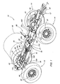
- FIG 1 is a part of an agricultural device, such.
- the main frame 12 is supported for movement across a field in a forward direction (F) of front axle controllable assemblies 14 and rear axle assemblies 16.
- the main frame 12 includes first and second longitudinally extending tubular main beams or rails 21, 22 which are connected to a front axle support frame 24 for the front axle assemblies 14 and to a rear axle support frame 26 for the rear axle assemblies 16.
- a motor-supporting frame 30 projects from the Vorderachsstützstrahlen 24 in the forward direction (F).
- the engine operates hydraulic drive means 32, which are arranged on the axle assemblies 14, 16 and drive the self-propelled sprayer 10.
- Various containers 36 are carried by container supports 38, including a larger container 36 for liquid.
- the container 36 has a lower outlet channel 40 which is arranged between the main supports 21, 22 and between the support frames 24, 26.
- a tubing assembly 50 is connected to the outlet channel 40 between the main supports 21, 22, wherein a liquid-transmitting connection to the container 36 is made.
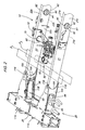
- the main beams 21, 22 have upper walls 21a, 22a and lower walls 21b, 22b joined together by opposite side walls 21c, 22c, thereby forming a substantially rectangular beam cross-section.
- the upper and lower walls 21a, 22a, 21b, 22b define parallel, horizontally oriented upper and lower planes (P1, P2) that lie in the region of the tubing assembly 50.
- the outlet channel 40 and the piping arrangement 50 lie substantially between the main beams 21, 22 between the planes P1, P2.
- the central portions of the main beams 21, 22 have openings 61, 62 for facilitating routing of ducts from an area between the inner side walls 22c to an area outside the main frame 12, while a wiring laid substantially between the levels P1, P2 is maintained to protect the lines, as well as a better appearance and a more straight course with minimal vertical changes in profile can be achieved.
- a supply line 70 extends through one of the openings 62 and constitutes a liquid line arranged horizontally between the outlet channel 40 and one outside the main carrier 21, 22.
- Operation control valve 72 is arranged.
- the outlet channel 40, the pipe assembly 50, including existing actuators, valves 72 and supply lines 70, as well as the hydraulically operated axle components 28 are located substantially between the planes P1, P2.
- Different types of control lines 76 including electrical and hydraulic lines, can be used between areas inside and outside the main carrier 21, 22 through the openings 61, 62 are laid, instead of above or below the main beams 21, 22nd
- the openings 61, 62 have tubular members or open cylindrical profiles 80 which are welded to the opposite side walls 21c and 22c of each main carrier 21 and 22, respectively.
- the profiles 80 have a centrally located separating gap 82 to ensure torsional flexibility of the main frame 12, while avoiding the occurrence of high stresses at the junctions between the profiles 80 and the side walls 21c, 22c.
- a sealing washer or a flexible seal 84 may be inserted at the separating gap 82, wherein it has been found that a sufficient sealing can be achieved by simply arranging each other in a tight manner.
- the interior of the main beams 21, 22 is substantially closed so that no foreign matter or contaminants enter the interior of the main beams 21, 22.
- the apertures 63, 64 which are shown substantially rectangular in shape, are reinforced with sheet metal assemblies 94 welded to the main beams 21, 22 to illustrate reinforcement of the main frame 12 and around the interior of the main beams 21, 22 against debris and contaminants Openings 63, 64 to protect.
- the openings 63, 64 are disposed side reinforcing plates 103, 104 which are welded to the side walls 21c, 22c, the side reinforcing plates 103, 104 having openings adapted to the openings 63, 64.
- the side reinforcing plates 103, 104 have inwardly directed circular cutouts 105, 106 to ensure a better lateral stress distribution near the openings 63, 64.
Landscapes
- Engineering & Computer Science (AREA)
- Life Sciences & Earth Sciences (AREA)
- Mechanical Engineering (AREA)
- Transportation (AREA)
- Wood Science & Technology (AREA)
- Pest Control & Pesticides (AREA)
- Environmental Sciences (AREA)
- Architecture (AREA)
- Structural Engineering (AREA)
- Chemical & Material Sciences (AREA)
- Combustion & Propulsion (AREA)
- Zoology (AREA)
- Insects & Arthropods (AREA)
- Health & Medical Sciences (AREA)
- Public Health (AREA)
- Catching Or Destruction (AREA)
- Special Spraying Apparatus (AREA)
- Details Or Accessories Of Spraying Plant Or Apparatus (AREA)
Claims (15)
- Châssis pour une machine agricole (10) comportant un premier et un deuxième supports principaux (21, 22) orientés dans le sens longitudinal, les supports principaux (21, 22) étant disposés en étant écartés transversalement l'un de l'autre, un réservoir (36) monté sur les supports principaux (21, 22) et comportant un conduit d'évacuation (40), positionné entre les supports principaux (21, 22), et un système de conduites tubulaires (50) orienté sensiblement horizontalement, caractérisé en ce qu'au moins un support principal (21, 22) comporte une zone munie d'une ouverture (61, 62), en ce que le système de conduites tubulaires (50) est guidé à partir du conduit d'évacuation (40) à travers l'ouverture (61, 62) dudit au moins un support principal (21, 22) et mène vers un emplacement en dehors du châssis (12), et en ce que l'ouverture (61, 62) est munie d'au moins un élément de renfort (80) afin de stabiliser ledit au moins un support principal (21, 22) dans la zone de l'ouverture (61, 62).
- Châssis selon la revendication 1, caractérisé en ce que les supports principaux (21, 22) sont réalisés sous forme de supports profilés creux avec des parois latérales (21 c, 22c) opposées, et les éléments de renfort (80) sont formés par des éléments tubulaires orientés dans le sens transversal, qui sont fixés contre les parois latérales (21 c, 22c).
- Châssis selon la revendication 1 ou 2, caractérisé en ce que les éléments de renfort (80) comportent une fente de séparation (82) afin de garantir une flexibilité de rotation des supports principaux (21, 22) et de limiter les tensions dans les parois latérales (21 c, 22c) dans les zones des ouvertures (61, 62).
- Châssis selon une ou plusieurs des revendications précédentes, caractérisé en ce que la fente de séparation (82) comporte des bords étroitement adjacents afin d'empêcher la pénétration de saletés dans les supports principaux (21, 22).
- Châssis selon une ou plusieurs des revendications précédentes, caractérisé en ce que les supports principaux (21, 22) comportent des surfaces inférieures (21 b, 22b), qui définissent un plan inférieur (P2), le système de conduites tubulaires (50) s'étendant entre les supports principaux (21, 22) au-dessus du plan inférieur (P2).
- Châssis selon une ou plusieurs des revendications précédentes, caractérisé en ce que les supports principaux (21, 22) comportent des surfaces supérieures (21 a, 22a), qui définissent un plan supérieur (P1), le système de conduites tubulaires (50) s'étendant entre les plans (P1, P2).
- Châssis selon une ou plusieurs des revendications précédentes, caractérisé en ce qu'il est prévu des systèmes d'essieux (14, 16) reliés au châssis (12), les supports principaux (21, 22) comportant des ouvertures (63, 64), à travers lesquelles peuvent être guidés des composants (28) pour les systèmes d'essieux (14, 16).
- Châssis selon une ou plusieurs des revendications précédentes, caractérisé en ce que les supports principaux (21, 22) comportent des tôles de renfort (113, 114) qui sont disposées en étant écartées verticalement par rapport aux ouvertures (63, 64) en vue de stabiliser les supports principaux (21, 22) dans la zone des ouvertures (63, 64).
- Châssis selon une ou plusieurs des revendications précédentes, caractérisé en ce que les supports principaux (21, 22) sont munis de tôles latérales (103, 104), agencées au niveau des ouvertures (63, 64), les tôles latérales (103, 104) comportant des zones d'extrémité orientées dans le sens longitudinal, qui sont munies de découpes (106) arrondies, en vue de répartir les sollicitations de tension sur les supports principaux (21, 22) à côté des ouvertures (63, 64).
- Châssis selon une ou plusieurs des revendications précédentes, caractérisé en ce que le système de conduites tubulaires (50) comporte une conduite d'alimentation (70).
- Châssis selon une ou plusieurs des revendications précédentes, caractérisé en ce que les composants (28) pour les systèmes d'essieux (14, 16) sont formés par des composants (28) pour le réglage de l'écartement de voie du système d'axes (14, 16), lesquels s'étendent horizontalement à travers les supports principaux (21, 22), les supports principaux (21, 22) masquant une partie des composants (28) de manière à les protéger contre les végétaux lorsque ceux-ci passent en dessous des supports principaux (21, 22).
- Châssis selon une ou plusieurs des revendications précédentes, caractérisé en ce que les systèmes d'essieux (14, 16) sont disposés de manière mobile et comportent des composants (28) hydrauliques qui peuvent être utilisés pour déplacer les systèmes d'essieux (14, 16).
- Châssis selon une ou plusieurs des revendications précédentes, caractérisé en ce que les éléments de renfort (80) comportent des tubes orientés horizontalement, qui sont fixés contre les parois latérales (21 c, 22c) et à travers lesquels peut être guidée au moins une partie du système de conduites tubulaires (50, 70).
- Châssis selon une ou plusieurs des revendications précédentes, caractérisé en ce qu'il est prévu des cadres de support d'essieux (24, 26), reliés aux supports principaux (21, 22), et les tôles de renfort (113, 114) sont reliées aux cadres de support d'essieux (24, 26) et aux supports principaux (21, 22), les tôles de renfort (113, 114) étant disposées dans la zone des ouvertures (63, 64).
- Machine agricole, en particulier machine agricole de pulvérisation, comportant un châssis selon une ou plusieurs des revendications précédentes.
Applications Claiming Priority (2)
| Application Number | Priority Date | Filing Date | Title |
|---|---|---|---|
| US10/459,314 US6942163B2 (en) | 2003-06-10 | 2003-06-10 | Implement with plumbing lines through a main frame tube |
| GB4593144 | 2003-06-10 |
Publications (2)
| Publication Number | Publication Date |
|---|---|
| EP1486401A1 EP1486401A1 (fr) | 2004-12-15 |
| EP1486401B1 true EP1486401B1 (fr) | 2007-01-03 |
Family
ID=33299672
Family Applications (1)
| Application Number | Title | Priority Date | Filing Date |
|---|---|---|---|
| EP04102521A Expired - Lifetime EP1486401B1 (fr) | 2003-06-10 | 2004-06-04 | Chassis |
Country Status (7)
| Country | Link |
|---|---|
| US (1) | US6942163B2 (fr) |
| EP (1) | EP1486401B1 (fr) |
| AR (1) | AR044658A1 (fr) |
| AT (1) | ATE350266T1 (fr) |
| BR (1) | BRPI0401938A (fr) |
| CA (1) | CA2470034A1 (fr) |
| DE (1) | DE502004002497D1 (fr) |
Cited By (2)
| Publication number | Priority date | Publication date | Assignee | Title |
|---|---|---|---|---|
| RU2624767C2 (ru) * | 2012-09-25 | 2017-07-06 | КЛААС Зельбстфаренде Эрнтемашинен ГмбХ | Рама для грузового транспортного средства |
| RU233378U1 (ru) * | 2025-01-20 | 2025-04-17 | Публичное акционерное общество "КАМАЗ" | Рама транспортного средства |
Families Citing this family (6)
| Publication number | Priority date | Publication date | Assignee | Title |
|---|---|---|---|---|
| DE202006005307U1 (de) * | 2006-04-01 | 2006-06-01 | Zunhammer, Sebastian, Dipl.-Ing. (FH) | Tankfahrzeug |
| US9840283B2 (en) * | 2016-02-23 | 2017-12-12 | Caterpillar Inc. | Machine frame |
| US10499562B2 (en) | 2017-07-24 | 2019-12-10 | Cnh Industrial America Llc | Rinse tank cutout and hose routing |
| US10569806B2 (en) | 2017-11-07 | 2020-02-25 | Cnh Industrial America Llc | Boxed plate construction frame with integral engine support section |
| CN110881455A (zh) * | 2019-12-11 | 2020-03-17 | 添宇 | 一种升降式多角度喷雾装置 |
| US20220274649A1 (en) * | 2022-05-18 | 2022-09-01 | MIG Marine | Chassis for recreational vehicle |
Family Cites Families (9)
| Publication number | Priority date | Publication date | Assignee | Title |
|---|---|---|---|---|
| US1422107A (en) * | 1920-10-15 | 1922-07-11 | Andrew A Kramer | Tank construction |
| GB258394A (en) | 1925-07-31 | 1926-09-23 | Thompson Brothers Bilston Ltd | Improved means for use in mounting a petrol or the like tank upon the chassis of a motor vehicle |
| US3857576A (en) * | 1974-03-18 | 1974-12-31 | T Wilt | Tank mounting structure |
| US5135258A (en) * | 1989-06-29 | 1992-08-04 | Buxton Jon S | Trailer with fuel tanks and means for pumping fuel |
| US5368332A (en) * | 1992-09-24 | 1994-11-29 | Dittrich; Keith J. | Applicator tank assembly for a tractor |
| FR2725417B1 (fr) * | 1994-10-07 | 2000-01-28 | Gflt Dev Pty Ltd | Remorque routiere |
| CA2141286C (fr) * | 1995-01-27 | 1998-05-26 | Gary E. Steadman | Citerne pour camion avec centre de gravite surbaisse |
| US6182588B1 (en) * | 1998-05-01 | 2001-02-06 | Flexi-Coil Ltd. | Hydraulic system having boost pump in series with a primary pump and a boost pump drive therefor |
| MA24870A1 (fr) | 1998-05-29 | 1999-12-31 | Espanola Petrol | Dispositif pour sceller des compartiments dans des citernes destinees au transport d'hydrocarbures |
-
2003
- 2003-06-10 US US10/459,314 patent/US6942163B2/en not_active Expired - Fee Related
-
2004
- 2004-06-04 DE DE502004002497T patent/DE502004002497D1/de not_active Expired - Fee Related
- 2004-06-04 CA CA002470034A patent/CA2470034A1/fr not_active Abandoned
- 2004-06-04 AT AT04102521T patent/ATE350266T1/de not_active IP Right Cessation
- 2004-06-04 EP EP04102521A patent/EP1486401B1/fr not_active Expired - Lifetime
- 2004-06-09 BR BR0401938-5A patent/BRPI0401938A/pt not_active IP Right Cessation
- 2004-06-10 AR ARP040102006A patent/AR044658A1/es unknown
Cited By (2)
| Publication number | Priority date | Publication date | Assignee | Title |
|---|---|---|---|---|
| RU2624767C2 (ru) * | 2012-09-25 | 2017-07-06 | КЛААС Зельбстфаренде Эрнтемашинен ГмбХ | Рама для грузового транспортного средства |
| RU233378U1 (ru) * | 2025-01-20 | 2025-04-17 | Публичное акционерное общество "КАМАЗ" | Рама транспортного средства |
Also Published As
| Publication number | Publication date |
|---|---|
| US20050001078A1 (en) | 2005-01-06 |
| DE502004002497D1 (de) | 2007-02-15 |
| ATE350266T1 (de) | 2007-01-15 |
| AR044658A1 (es) | 2005-09-21 |
| US6942163B2 (en) | 2005-09-13 |
| CA2470034A1 (fr) | 2004-12-10 |
| EP1486401A1 (fr) | 2004-12-15 |
| BRPI0401938A (pt) | 2005-01-25 |
Similar Documents
| Publication | Publication Date | Title |
|---|---|---|
| DE69004287T2 (de) | Hydraulische Rohranordnung für einen Heckbagger. | |
| EP0909855A2 (fr) | Véhicule chargeur | |
| EP2297020A1 (fr) | Grue automotrice avec guidage de flexible | |
| DE10246447A1 (de) | Fahrbare Betonpumpe mit einem Aufbaurahmen | |
| EP1486401B1 (fr) | Chassis | |
| EP2265521B1 (fr) | Bande transporteuse pour une installation de transport en longueur comportant des parois latérales s'étendant en longueur | |
| EP3613659A1 (fr) | Dispositif de conduit d'air de véhicule automobile et véhicule automobile | |
| EP3641129A1 (fr) | Procédé de montage permettant de monter une construction modulaire et, en particulier de monter des installations photovoltaïques | |
| DE102013110203B4 (de) | Tankmodul für einen Fahrzeuganhänger, Fahrzeuganhänger und Verfahren zum Nachrüsten eines Fahrzeuganhängers mit einem derartigen Tankmodul | |
| DE2714028A1 (de) | Rahmen zum anbau eines arbeitsgeraetes, insbesondere eines hecktiefloeffels, an einem fahrzeug, wie z.b. traktor o.dgl. | |
| EP3800299B1 (fr) | Équipement, en particulier chargeur sur roues | |
| DE202011106833U1 (de) | Schnellkupplungssystem für Anbaugeräte, insbesondere für landwirtschaftliche Anbaugeräte | |
| DE69628219T2 (de) | Montageeinrichtung für hin- und hergehende Gliederbandförderer | |
| DE102009052748A1 (de) | Container-Compoundieranlage | |
| EP1767426B1 (fr) | Véhicule ferroviaire à deux niveaux avec au moins un conduit s'étendant d'une extrémité à l'autre | |
| EP4071302B1 (fr) | Fraiseuse autonome pour découper les sols | |
| DE102015117571B3 (de) | Bodenmodul eines Flugzeugfrachtraumes | |
| DE102021118786A1 (de) | Selbstfahrende bodenfräsmaschine | |
| EP3207193A1 (fr) | Bras de mât d'un mât distributeur de béton | |
| EP2066538A1 (fr) | Portique de lavage et procédé de montage d'un portique de lavage | |
| DE102021110776B4 (de) | Kabelpflugsystem | |
| EP3964657B1 (fr) | Véhicule de nettoyage de canal | |
| DE102019213008B4 (de) | Verfahren zur Montage von Fördergurtanlagen | |
| EP4094986B1 (fr) | Remorque destinée au transport des liquides | |
| EP1713965B1 (fr) | Ensemble de bancs d'etirage pour metiers a filer |
Legal Events
| Date | Code | Title | Description |
|---|---|---|---|
| PUAI | Public reference made under article 153(3) epc to a published international application that has entered the european phase |
Free format text: ORIGINAL CODE: 0009012 |
|
| AK | Designated contracting states |
Kind code of ref document: A1 Designated state(s): AT BE BG CH CY CZ DE DK EE ES FI FR GB GR HU IE IT LI LU MC NL PL PT RO SE SI SK TR |
|
| AX | Request for extension of the european patent |
Extension state: AL HR LT LV MK |
|
| 17P | Request for examination filed |
Effective date: 20050615 |
|
| AKX | Designation fees paid |
Designated state(s): AT BE BG CH CY CZ DE DK EE ES FI FR GB GR HU IE IT LI LU MC NL PL PT RO SE SI SK TR |
|
| GRAP | Despatch of communication of intention to grant a patent |
Free format text: ORIGINAL CODE: EPIDOSNIGR1 |
|
| GRAS | Grant fee paid |
Free format text: ORIGINAL CODE: EPIDOSNIGR3 |
|
| GRAA | (expected) grant |
Free format text: ORIGINAL CODE: 0009210 |
|
| AK | Designated contracting states |
Kind code of ref document: B1 Designated state(s): AT BE BG CH CY CZ DE DK EE ES FI FR GB GR HU IE IT LI LU MC NL PL PT RO SE SI SK TR |
|
| PG25 | Lapsed in a contracting state [announced via postgrant information from national office to epo] |
Ref country code: FI Free format text: LAPSE BECAUSE OF FAILURE TO SUBMIT A TRANSLATION OF THE DESCRIPTION OR TO PAY THE FEE WITHIN THE PRESCRIBED TIME-LIMIT Effective date: 20070103 Ref country code: SI Free format text: LAPSE BECAUSE OF FAILURE TO SUBMIT A TRANSLATION OF THE DESCRIPTION OR TO PAY THE FEE WITHIN THE PRESCRIBED TIME-LIMIT Effective date: 20070103 Ref country code: PL Free format text: LAPSE BECAUSE OF FAILURE TO SUBMIT A TRANSLATION OF THE DESCRIPTION OR TO PAY THE FEE WITHIN THE PRESCRIBED TIME-LIMIT Effective date: 20070103 Ref country code: DK Free format text: LAPSE BECAUSE OF FAILURE TO SUBMIT A TRANSLATION OF THE DESCRIPTION OR TO PAY THE FEE WITHIN THE PRESCRIBED TIME-LIMIT Effective date: 20070103 Ref country code: IE Free format text: LAPSE BECAUSE OF FAILURE TO SUBMIT A TRANSLATION OF THE DESCRIPTION OR TO PAY THE FEE WITHIN THE PRESCRIBED TIME-LIMIT Effective date: 20070103 |
|
| REG | Reference to a national code |
Ref country code: GB Ref legal event code: FG4D Free format text: NOT ENGLISH |
|
| REF | Corresponds to: |
Ref document number: 502004002497 Country of ref document: DE Date of ref document: 20070215 Kind code of ref document: P |
|
| REG | Reference to a national code |
Ref country code: IE Ref legal event code: FG4D Free format text: LANGUAGE OF EP DOCUMENT: GERMAN |
|
| GBT | Gb: translation of ep patent filed (gb section 77(6)(a)/1977) |
Effective date: 20070215 |
|
| PG25 | Lapsed in a contracting state [announced via postgrant information from national office to epo] |
Ref country code: SE Free format text: LAPSE BECAUSE OF FAILURE TO SUBMIT A TRANSLATION OF THE DESCRIPTION OR TO PAY THE FEE WITHIN THE PRESCRIBED TIME-LIMIT Effective date: 20070403 |
|
| PG25 | Lapsed in a contracting state [announced via postgrant information from national office to epo] |
Ref country code: BG Free format text: LAPSE BECAUSE OF FAILURE TO SUBMIT A TRANSLATION OF THE DESCRIPTION OR TO PAY THE FEE WITHIN THE PRESCRIBED TIME-LIMIT Effective date: 20070404 |
|
| PG25 | Lapsed in a contracting state [announced via postgrant information from national office to epo] |
Ref country code: ES Free format text: LAPSE BECAUSE OF FAILURE TO SUBMIT A TRANSLATION OF THE DESCRIPTION OR TO PAY THE FEE WITHIN THE PRESCRIBED TIME-LIMIT Effective date: 20070414 |
|
| PGFP | Annual fee paid to national office [announced via postgrant information from national office to epo] |
Ref country code: DE Payment date: 20070522 Year of fee payment: 4 |
|
| PG25 | Lapsed in a contracting state [announced via postgrant information from national office to epo] |
Ref country code: PT Free format text: LAPSE BECAUSE OF FAILURE TO SUBMIT A TRANSLATION OF THE DESCRIPTION OR TO PAY THE FEE WITHIN THE PRESCRIBED TIME-LIMIT Effective date: 20070604 |
|
| ET | Fr: translation filed | ||
| REG | Reference to a national code |
Ref country code: IE Ref legal event code: FD4D |
|
| PLBE | No opposition filed within time limit |
Free format text: ORIGINAL CODE: 0009261 |
|
| STAA | Information on the status of an ep patent application or granted ep patent |
Free format text: STATUS: NO OPPOSITION FILED WITHIN TIME LIMIT |
|
| PG25 | Lapsed in a contracting state [announced via postgrant information from national office to epo] |
Ref country code: SK Free format text: LAPSE BECAUSE OF FAILURE TO SUBMIT A TRANSLATION OF THE DESCRIPTION OR TO PAY THE FEE WITHIN THE PRESCRIBED TIME-LIMIT Effective date: 20070103 |
|
| 26N | No opposition filed |
Effective date: 20071005 |
|
| BERE | Be: lapsed |
Owner name: DEERE & CY Effective date: 20070630 |
|
| PG25 | Lapsed in a contracting state [announced via postgrant information from national office to epo] |
Ref country code: RO Free format text: LAPSE BECAUSE OF FAILURE TO SUBMIT A TRANSLATION OF THE DESCRIPTION OR TO PAY THE FEE WITHIN THE PRESCRIBED TIME-LIMIT Effective date: 20070103 Ref country code: CZ Free format text: LAPSE BECAUSE OF FAILURE TO SUBMIT A TRANSLATION OF THE DESCRIPTION OR TO PAY THE FEE WITHIN THE PRESCRIBED TIME-LIMIT Effective date: 20070103 |
|
| PG25 | Lapsed in a contracting state [announced via postgrant information from national office to epo] |
Ref country code: MC Free format text: LAPSE BECAUSE OF NON-PAYMENT OF DUE FEES Effective date: 20070630 |
|
| PG25 | Lapsed in a contracting state [announced via postgrant information from national office to epo] |
Ref country code: BE Free format text: LAPSE BECAUSE OF NON-PAYMENT OF DUE FEES Effective date: 20070630 |
|
| PG25 | Lapsed in a contracting state [announced via postgrant information from national office to epo] |
Ref country code: IT Free format text: LAPSE BECAUSE OF FAILURE TO SUBMIT A TRANSLATION OF THE DESCRIPTION OR TO PAY THE FEE WITHIN THE PRESCRIBED TIME-LIMIT Effective date: 20070103 Ref country code: GR Free format text: LAPSE BECAUSE OF FAILURE TO SUBMIT A TRANSLATION OF THE DESCRIPTION OR TO PAY THE FEE WITHIN THE PRESCRIBED TIME-LIMIT Effective date: 20070404 |
|
| PGFP | Annual fee paid to national office [announced via postgrant information from national office to epo] |
Ref country code: FR Payment date: 20070618 Year of fee payment: 4 |
|
| PG25 | Lapsed in a contracting state [announced via postgrant information from national office to epo] |
Ref country code: AT Free format text: LAPSE BECAUSE OF NON-PAYMENT OF DUE FEES Effective date: 20070604 |
|
| PG25 | Lapsed in a contracting state [announced via postgrant information from national office to epo] |
Ref country code: EE Free format text: LAPSE BECAUSE OF FAILURE TO SUBMIT A TRANSLATION OF THE DESCRIPTION OR TO PAY THE FEE WITHIN THE PRESCRIBED TIME-LIMIT Effective date: 20070103 |
|
| REG | Reference to a national code |
Ref country code: CH Ref legal event code: PL |
|
| GBPC | Gb: european patent ceased through non-payment of renewal fee |
Effective date: 20080604 |
|
| NLV4 | Nl: lapsed or anulled due to non-payment of the annual fee |
Effective date: 20090101 |
|
| REG | Reference to a national code |
Ref country code: FR Ref legal event code: ST Effective date: 20090228 |
|
| PG25 | Lapsed in a contracting state [announced via postgrant information from national office to epo] |
Ref country code: DE Free format text: LAPSE BECAUSE OF NON-PAYMENT OF DUE FEES Effective date: 20090101 |
|
| PG25 | Lapsed in a contracting state [announced via postgrant information from national office to epo] |
Ref country code: NL Free format text: LAPSE BECAUSE OF NON-PAYMENT OF DUE FEES Effective date: 20090101 |
|
| PG25 | Lapsed in a contracting state [announced via postgrant information from national office to epo] |
Ref country code: GB Free format text: LAPSE BECAUSE OF NON-PAYMENT OF DUE FEES Effective date: 20080604 Ref country code: LI Free format text: LAPSE BECAUSE OF NON-PAYMENT OF DUE FEES Effective date: 20080630 Ref country code: CH Free format text: LAPSE BECAUSE OF NON-PAYMENT OF DUE FEES Effective date: 20080630 |
|
| PG25 | Lapsed in a contracting state [announced via postgrant information from national office to epo] |
Ref country code: CY Free format text: LAPSE BECAUSE OF FAILURE TO SUBMIT A TRANSLATION OF THE DESCRIPTION OR TO PAY THE FEE WITHIN THE PRESCRIBED TIME-LIMIT Effective date: 20070103 |
|
| PG25 | Lapsed in a contracting state [announced via postgrant information from national office to epo] |
Ref country code: LU Free format text: LAPSE BECAUSE OF NON-PAYMENT OF DUE FEES Effective date: 20070604 Ref country code: FR Free format text: LAPSE BECAUSE OF NON-PAYMENT OF DUE FEES Effective date: 20080630 |
|
| PG25 | Lapsed in a contracting state [announced via postgrant information from national office to epo] |
Ref country code: HU Free format text: LAPSE BECAUSE OF FAILURE TO SUBMIT A TRANSLATION OF THE DESCRIPTION OR TO PAY THE FEE WITHIN THE PRESCRIBED TIME-LIMIT Effective date: 20070704 Ref country code: TR Free format text: LAPSE BECAUSE OF FAILURE TO SUBMIT A TRANSLATION OF THE DESCRIPTION OR TO PAY THE FEE WITHIN THE PRESCRIBED TIME-LIMIT Effective date: 20070103 |