EP1486439A2 - Système pour déplacer horizontalement en translation et orienter des articles, notamment des récipients en mouvement continu - Google Patents
Système pour déplacer horizontalement en translation et orienter des articles, notamment des récipients en mouvement continu Download PDFInfo
- Publication number
- EP1486439A2 EP1486439A2 EP04013071A EP04013071A EP1486439A2 EP 1486439 A2 EP1486439 A2 EP 1486439A2 EP 04013071 A EP04013071 A EP 04013071A EP 04013071 A EP04013071 A EP 04013071A EP 1486439 A2 EP1486439 A2 EP 1486439A2
- Authority
- EP
- European Patent Office
- Prior art keywords
- translation
- rotary
- along
- orientation
- units
- Prior art date
- Legal status (The legal status is an assumption and is not a legal conclusion. Google has not performed a legal analysis and makes no representation as to the accuracy of the status listed.)
- Granted
Links
Images




Classifications
-
- B—PERFORMING OPERATIONS; TRANSPORTING
- B65—CONVEYING; PACKING; STORING; HANDLING THIN OR FILAMENTARY MATERIAL
- B65G—TRANSPORT OR STORAGE DEVICES, e.g. CONVEYORS FOR LOADING OR TIPPING, SHOP CONVEYOR SYSTEMS OR PNEUMATIC TUBE CONVEYORS
- B65G47/00—Article or material-handling devices associated with conveyors; Methods employing such devices
- B65G47/74—Feeding, transfer, or discharging devices of particular kinds or types
- B65G47/84—Star-shaped wheels or devices having endless travelling belts or chains, the wheels or devices being equipped with article-engaging elements
- B65G47/841—Devices having endless travelling belts or chains equipped with article-engaging elements
- B65G47/842—Devices having endless travelling belts or chains equipped with article-engaging elements the article-engaging elements being grippers
-
- B—PERFORMING OPERATIONS; TRANSPORTING
- B65—CONVEYING; PACKING; STORING; HANDLING THIN OR FILAMENTARY MATERIAL
- B65G—TRANSPORT OR STORAGE DEVICES, e.g. CONVEYORS FOR LOADING OR TIPPING, SHOP CONVEYOR SYSTEMS OR PNEUMATIC TUBE CONVEYORS
- B65G47/00—Article or material-handling devices associated with conveyors; Methods employing such devices
- B65G47/22—Devices influencing the relative position or the attitude of articles during transit by conveyors
- B65G47/24—Devices influencing the relative position or the attitude of articles during transit by conveyors orientating the articles
- B65G47/244—Devices influencing the relative position or the attitude of articles during transit by conveyors orientating the articles by turning them about an axis substantially perpendicular to the conveying plane
-
- B—PERFORMING OPERATIONS; TRANSPORTING
- B65—CONVEYING; PACKING; STORING; HANDLING THIN OR FILAMENTARY MATERIAL
- B65G—TRANSPORT OR STORAGE DEVICES, e.g. CONVEYORS FOR LOADING OR TIPPING, SHOP CONVEYOR SYSTEMS OR PNEUMATIC TUBE CONVEYORS
- B65G2201/00—Indexing codes relating to handling devices, e.g. conveyors, characterised by the type of product or load being conveyed or handled
- B65G2201/02—Articles
- B65G2201/0235—Containers
- B65G2201/0244—Bottles
Definitions
- the present invention relates to a system for horizontally translating and orientating objects, particularly containers, with continuous motion.
- the object of the present invention is to overcome the aforesaid drawbacks.
- the invention which is characterized by the claims, resolves the problem of creating a system for horizontally translating and orientating objects, particularly containers, with continuous motion, in which the said system is characterized in that it comprises a translation and orientation line, comprising: first conveyor means, in a lower position, designed to translate the containers, in single file, one after another, in the downstream direction with respect to the aforesaid translation and orientation line; second conveyor means, in an upper position, designed to translate one or more rotary gripper units, in single file, one after another, in the downstream direction with respect to the aforesaid translation and orientation line, in which each rotary gripper unit includes first device for opening and closing the jaws of the gripper and second device for rotating the said gripper; sensor means, positioned in the proximity of the upstream portion of the said translation and orientation line, designed to read the orientation of the containers; first actuator means, designed to control the said first device for opening and closing the jaws of the rotary grippers of the rotary gripper units; second actuator means, designed to control the said
- the advantages provided by the present invention consist essentially in the fact that the system is more reliable, more efficient and safer, in the fact that the containers are securely translated and orientated, in the fact that operations for a change of format are facilitated, and in the fact that higher operating speeds can be used with a consequent increase in production capacity.
- the system for horizontally translating and orientating objects, particularly containers C, with continuous motion comprises a translation and orientation line extending longitudinally and rectilinearly.
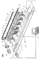
- the said translation and orientation line substantially comprises: first conveyor means 10, in a lower position, designed to translate the containers C, in single file, one after another, in the downstream direction with respect to the aforesaid translation and orientation line, with respect to the direction of translation indicated by the arrow F; second conveyor means 20, in an upper position, designed to translate one or more units 30 with rotary grippers 40, in single file, one after another, in the downstream direction with respect to the aforesaid translation and orientation line, in which each unit 30 with a rotary gripper 40 includes first device 80 for opening and closing the jaws 40a-40b of the rotary gripper and second device 90 for rotating the said gripper 40; sensor means S, positioned in the proximity of the upstream portion of the said translation and orientation line, designed to read the orientation of the containers C; first actuator means 50a and 50b, designed to control the opening and/or the closing of the jaws 40a and 40b of the rotary grippers 40; second actuator means 60, designed to control the rotation of the rotary grippers 40; and synchron
- these comprise a conveyor 11 having a conveyor belt 12 running in a closed loop, in which the said conveyor 11 is driven by a corresponding servomotor M10, such as a controllable brushless servomotor, which is controlled by the synchronization means 70, in which the upper branch of the said closed loop extends in a lower position in the downstream direction with respect to the aforesaid translation and orientation line, to support the bases of the containers C.
- a servomotor M10 such as a controllable brushless servomotor
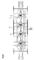
- the first conveyor means 10 comprise two separate conveyors with conveyor belts, and more particularly a first conveyor 111a with a conveyor belt 112a running in a closed loop, driven by a corresponding servomotor M110a controlled by the synchronization means 70, and a second conveyor 111 b with a conveyor belt 112b running in a closed loop, driven by a corresponding servomotor M110b controlled by the synchronization means 70.
- a transmission between the conveyors 111 a and 111 b in order to drive them by means of a single servomotor.
- the said conveyor belts 12, 112a, 112b can be made in the form of suction belts, for example by making the said belts perforated and/or porous and/or of the articulated mesh type, and by providing under the upper branches of the belts a suction vessel 13, 113a, 113b connected to a suction source which is not shown.
- the said belts 12, 112a, 112b can be provided if required with a container support surface having a low frictional coefficient, in order to facilitate the rotation of the containers, as will be explained more fully below.
- the said second conveyor means 20 comprise a belt or chain conveyor 21a and 21b, running in closed loops in corresponding vertical and longitudinal planes, by means of corresponding pairs of sprockets, in which the said conveyor is driven by a servomotor M20, for example a controllable brushless servomotor, which is controlled by the synchronization means 70, in which the said chains 21 a and 21 b are designed to carry transverse bars 22a-22b on which the aforesaid units 30 with rotary grippers 40 are positioned.
- a servomotor M20 for example a controllable brushless servomotor
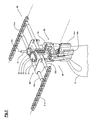
- Each unit 30 with a rotary gripper 40 includes a first device 80, for opening and closing the jaws 40a and 40b on command, and a second device 90, for rotating the rotary gripper 40 on command.
- the said first device 80 comprises a first operating element 81, the upper end of which extends upwards beyond the plane of translation of the said units 30, whose said first element 81, during the translation of the said units 30 along the said translation and orientation line, as described more fully below, interacts with the first actuator means 50b and 50a (see Fig. 1) positioned along the said translation and orientation line, to cause the opening and closing of the jaws 40a and 40b.
- the said first device 80 comprises, for example, a sleeve 82, supported rotatably by a frame 31 of the unit 30, in which the said sleeve 82 carries a gear wheel 92 fixed at its upper end, for the reasons which will be stated more fully below, and a rotating frame 83, for supporting the rotary gripper 40, at its lower end.
- the said element 81 is shaped in the form of a bar which is supported slidably and axially within the said sleeve 82, in which the said bar 81 is pushed upwards by a spring 84, whose lower end presses on a ring 85 fixed to the sleeve 82 and whose upper end presses on a bush 86, in which the upper end of the bush bears on a shoulder 81 a formed on the said shaft 81 in order to push the said shaft 81 upwards.
- the aforesaid shaft 81 is therefore free to slide, by means of axial oscillations, axially downwards and then to be pushed back upwards by the spring 84, and, substantially, in the course the said movements it opens and closes the gripping jaws 40a-40b of two levers 41 a and 41 b, pivoted at 42a and 42b on the rotating frame 83, in which the upper ends of the said levers 41 a and 41b are connected to the lower end of the said operating bar 81, by means of articulations 43a-44 and 43b-44 respectively.
- the mechanism described above in relation to the rotary gripper 40 can also be made in other embodiments, and moreover the gripping jaws 40a and 40b can have gripping profiles designed to match the shape of the containers and/or gripping buffers with a greater or lesser thickness, to enable the format to be changed.
- the said second member 90 comprises a second operating element 91, which is supported movably by the said unit 30, in which the said second operating element 91 is made to interact, during the translation of the said unit 30 along the translation and orientation line, with second actuator means 60, which are positioned along the translation and orientation line as described more fully below.
- the said second element 91 is a roller spindle supported and positioned on the upper face of a toothed sector 94, in an eccentric position with respect to the centre 93 of pivoting and rotation of the said toothed sector 94, in which the latter is engaged with the gear wheel 92 fixed on the top of the sleeve 82, in such a way that the rotational oscillations imparted to the said toothed sector 94 cause a rotation of the wheel 92 and consequently a rotation of the rotating frame 83 and of the rotary gripper 40.
- these preferably comprise an optoelectronic sensor, but in practice can also use other electromechanical and/or electropneumatic sensors and/or sensors of other types, preferably selected in accordance with the shapes of the containers to be orientated, and in any case designed to read the orientation of the said containers and to communicate the said reading to the synchronization means 70.
- the aforementioned first actuator means 50a-50b comprise two cam profiles, positioned substantially along the initial and final segments of the lower orbital path described by first operating members 81 of the units 30 and, additionally, in the area of downward return and upward return of the said units 30, in order to open the jaws 40a-40b before they reach a position, in their movement from above to below, at the side of the containers C in the initial area and in the final area of the translation and orientation line for the reasons explained below.
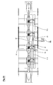
- the second actuator means 60 substantially comprise (see Fig. 1) a primary track 61a-61b and a secondary branch track 62, extending longitudinally along the said translation and orientation line, and a switch blade 63 which is moved into its two operating positions of switching and non-switching by means of an actuator 64, in this particular case a brushless motor M60, which is connected to the synchronization means 70, making it possible to guide each roller spindle 91 into one or other of the said tracks 61 b and 62 selectively, in succession and with the correct timing, during the downstream translation of the unit 30.
- the containers C are fed in the proximity of the entry end of the system proposed by the present invention, in a staged way and in synchronization with the units 30 with rotary grippers 40 which are being translated downwards in the proximity of the start of the translation and orientation line.
- the upper end of the bar 81 encounters the cam profile 50a, causing the jaws 40a and 40b to open, and then, when the jaws 40a-40b move downwards they are positioned without interference on the opposite sides of the container C, and then close and grip the container when the said cam profile is interrupted, because of the return action of the spring 84.
- the sensor means S read the horizontal orientation of each container C being translated, and each individual reading is then associated by the synchronization means 70 with the corresponding unit 30 with the rotary gripper 40 which grips the container.
- Each individual unit 30 with a rotary gripper 40 and the corresponding gripped container C is then translated along a second central translation and orientation segment of the translation and orientation line, and, in the said second segment, the synchronization means 70, according to the orientation of the container associated with the unit 30 which is being translated, set the switch blade 64 to one of its two working positions, and, more particularly, if the unit 30 has been associated with a correctly orientated container, the said blade is positioned in alignment with the primary track 61 b so that the roller spindle 91 is not diverted, whereas, if the unit 30 has been associated with an incorrectly orientated container, the said blade 64 is set to the switching position in order to divert the roller spindle into the branch track 62.
- one or more guides are positioned in the upper part of the conveyor 20 carrying the gripper units 30, and these guides move the roller spindles 91 into the correct initial position during the said passive travel of the said units 30, in order to enable a new operating travel to be commenced when the said units arrive in the proximity of the start of the translation and orientation line.
- a third device 300 is additionally provided, and is designed to prevent or allow the rotation of the said rotary gripper 40.
- the said device 300 which preferably acts on the gear wheel 92 or on the sleeve 82 by a coupling or clutch means, such as a ratchet gear, comprises an operating element 301, positioned at the end of a lever 302, whose opposite end carries a locking tooth 303 designed to be inserted between the teeth of the wheel 92, in which the said lever is returned to the position of insertion of the tooth 303 by means of a spring 304.
- the said roller 301 is designed to interact with a cam profile 400 extending longitudinally, preferably only along the second, central, translation and orientation segment, in order to achieve, in the course of the translation of the unit 30 with the rotary gripper 40 along the translation and orientation line, the locking of the rotary gripper 40 along the first translation and gripping segment, the contact of the roller 301 with the profile 400, and consequently the release of the rotary gripper 40, along the second translation and orientation segment, and the locking of the rotary gripper 40 along the third translation and release segment.
Landscapes
- Engineering & Computer Science (AREA)
- Mechanical Engineering (AREA)
- Attitude Control For Articles On Conveyors (AREA)
- Specific Conveyance Elements (AREA)
Applications Claiming Priority (2)
| Application Number | Priority Date | Filing Date | Title |
|---|---|---|---|
| ITBO20030352 | 2003-06-10 | ||
| IT2003BO000352A ITBO20030352A1 (it) | 2003-06-10 | 2003-06-10 | Sistema per traslare et orientare orizzontalmente degli oggetti, in particolare contenitori, con moto continuo |
Publications (3)
| Publication Number | Publication Date |
|---|---|
| EP1486439A2 true EP1486439A2 (fr) | 2004-12-15 |
| EP1486439A3 EP1486439A3 (fr) | 2005-05-18 |
| EP1486439B1 EP1486439B1 (fr) | 2007-10-10 |
Family
ID=29560559
Family Applications (1)
| Application Number | Title | Priority Date | Filing Date |
|---|---|---|---|
| EP04013071A Expired - Lifetime EP1486439B1 (fr) | 2003-06-10 | 2004-06-03 | Système pour déplacer horizontalement en translation et orienter des articles, notamment des récipients en mouvement continu |
Country Status (4)
| Country | Link |
|---|---|
| EP (1) | EP1486439B1 (fr) |
| AT (1) | ATE375317T1 (fr) |
| DE (1) | DE602004009366D1 (fr) |
| IT (1) | ITBO20030352A1 (fr) |
Cited By (20)
| Publication number | Priority date | Publication date | Assignee | Title |
|---|---|---|---|---|
| ES2249148A1 (es) * | 2004-07-05 | 2006-03-16 | Dositecno95, S.L. | Procedimiento y maquina para el lavado de botellas. |
| EP1790593A1 (fr) * | 2005-11-24 | 2007-05-30 | OPM S.p.A. | Transporteur circulaire pour le transfert de produits, en particulier des produits alimentaires |
| WO2007093400A1 (fr) * | 2006-02-16 | 2007-08-23 | Aetna Group S.P.A. | Appareil et procede d'orientation d'articles |
| WO2007141817A1 (fr) * | 2006-06-05 | 2007-12-13 | Sps Italiana Pack Systems Spa | Tapis de transport et dispositif de positionnement de produits ensachés |
| NL2004278C2 (en) * | 2010-02-22 | 2011-08-23 | Sluis Cigar Machinery B V V D | Transfer apparatus for transferring an item. |
| ITBO20100101A1 (it) * | 2010-02-24 | 2011-08-25 | Cosmopack Srl | Metodo e sistema per accumulare ed alimentare oggetti |
| EP2397846A1 (fr) * | 2010-06-18 | 2011-12-21 | Sgd S.A. | Procédé de contrôle optique automatisé de décor et dispositif de contrôle optique automatisé correspondant |
| WO2012130973A1 (fr) * | 2011-03-31 | 2012-10-04 | Sidel Participations | Dispositif de transfert de recipients avec indexation angulaire par contact entre un element d'indexation et un troncon cylindrique du recipient |
| WO2013072014A1 (fr) * | 2011-11-15 | 2013-05-23 | Iwk Verpackungstechnik Gmbh | Dispositif permettant de retourner une boîte d'emballage |
| CN103863600A (zh) * | 2012-12-18 | 2014-06-18 | 莫迪维克贸易有限公司 | 热成形包装机和方法 |
| US8776988B2 (en) | 2009-09-29 | 2014-07-15 | Sluis Cigar Machinery B.V. | Transfer apparatus for transferring an item |
| CN105346994A (zh) * | 2015-11-13 | 2016-02-24 | 无锡市麦杰机械工程有限公司 | 在线转包机构 |
| ITUB20160455A1 (it) * | 2016-01-21 | 2017-07-21 | Elisam S R L | Apparecchiatura per orientare contenitori |
| IT201600084100A1 (it) * | 2016-08-10 | 2018-02-10 | Cosmopack S R L | sistema per manipolare oggetti |
| WO2018085830A3 (fr) * | 2016-11-07 | 2018-06-07 | R. A Jones & Co. | Appareil et procédés pour applications d'orientation de produits et de remplacement de produits manquants |
| CN111498232A (zh) * | 2020-05-25 | 2020-08-07 | 佛山市海天(高明)调味食品有限公司 | 自转式转瓶机 |
| WO2020228092A1 (fr) * | 2019-05-10 | 2020-11-19 | 李江 | Système de bande transporteuse |
| WO2021188924A1 (fr) * | 2020-03-19 | 2021-09-23 | Illinois Tool Works Inc. | Dispositif pour faire tourner des articles d'un groupe d'articles en vrac, machine d'emballage dotée d'un tel dispositif et procédé pour faire tourner des articles d'un groupe d'articles en vrac à l'aide d'un tel dispositif |
| EP3982773A1 (fr) * | 2019-06-13 | 2022-04-20 | G.D Societa' Per Azioni | Système de transport pour une cartouche au moins partiellement complète, en particulier pour une cigarette électronique |
| CN119240278A (zh) * | 2024-10-21 | 2025-01-03 | 中煤科工机器人科技有限公司 | 一种矿钢丝绳自行走皮带巡检装置 |
Families Citing this family (1)
| Publication number | Priority date | Publication date | Assignee | Title |
|---|---|---|---|---|
| EP3943423A1 (fr) * | 2020-07-24 | 2022-01-26 | WestRock Packaging Systems, LLC | Système et procédé de groupement de récipients |
Family Cites Families (4)
| Publication number | Priority date | Publication date | Assignee | Title |
|---|---|---|---|---|
| US3837474A (en) * | 1971-11-12 | 1974-09-24 | Dalamere & Williams Co Ltd | Article handling apparatus |
| GB2230245A (en) * | 1989-04-12 | 1990-10-17 | Noshe Eng Ltd | Article orientators |
| BE1013005A3 (nl) * | 1998-08-24 | 2001-07-03 | Boucherie Nv G B | Werkwijze en inrichting voor het ordenen van tandenborstellichamen en machine die met zulke inrichting is uitgerust. |
| NL1014063C2 (nl) * | 2000-01-14 | 2001-07-17 | Food Processing Systems | Inrichting voor het bij behoud van voorwaartse transportsnelheid herpositioneren van producten. |
-
2003
- 2003-06-10 IT IT2003BO000352A patent/ITBO20030352A1/it unknown
-
2004
- 2004-06-03 AT AT04013071T patent/ATE375317T1/de not_active IP Right Cessation
- 2004-06-03 EP EP04013071A patent/EP1486439B1/fr not_active Expired - Lifetime
- 2004-06-03 DE DE602004009366T patent/DE602004009366D1/de not_active Expired - Lifetime
Cited By (29)
| Publication number | Priority date | Publication date | Assignee | Title |
|---|---|---|---|---|
| ES2249148A1 (es) * | 2004-07-05 | 2006-03-16 | Dositecno95, S.L. | Procedimiento y maquina para el lavado de botellas. |
| ES2249148B1 (es) * | 2004-07-05 | 2007-08-16 | Dositecno95, S.L. | Procedimiento y maquina para el lavado de botellas. |
| EP1790593A1 (fr) * | 2005-11-24 | 2007-05-30 | OPM S.p.A. | Transporteur circulaire pour le transfert de produits, en particulier des produits alimentaires |
| WO2007093400A1 (fr) * | 2006-02-16 | 2007-08-23 | Aetna Group S.P.A. | Appareil et procede d'orientation d'articles |
| US7870943B2 (en) | 2006-02-16 | 2011-01-18 | Aetna Group S.P.A. | Apparatus and method for orienting articles |
| WO2007141817A1 (fr) * | 2006-06-05 | 2007-12-13 | Sps Italiana Pack Systems Spa | Tapis de transport et dispositif de positionnement de produits ensachés |
| US8776988B2 (en) | 2009-09-29 | 2014-07-15 | Sluis Cigar Machinery B.V. | Transfer apparatus for transferring an item |
| NL2004278C2 (en) * | 2010-02-22 | 2011-08-23 | Sluis Cigar Machinery B V V D | Transfer apparatus for transferring an item. |
| EP2361858A1 (fr) * | 2010-02-24 | 2011-08-31 | Cosmopack S.r.l. | Procédé et système pour accumuler et alimenter des objets |
| ITBO20100101A1 (it) * | 2010-02-24 | 2011-08-25 | Cosmopack Srl | Metodo e sistema per accumulare ed alimentare oggetti |
| EP2397846A1 (fr) * | 2010-06-18 | 2011-12-21 | Sgd S.A. | Procédé de contrôle optique automatisé de décor et dispositif de contrôle optique automatisé correspondant |
| FR2961599A1 (fr) * | 2010-06-18 | 2011-12-23 | Sgd Sa | Procede de controle optique automatise de decor et dispositif de controle optique automatise correspondant. |
| WO2012130973A1 (fr) * | 2011-03-31 | 2012-10-04 | Sidel Participations | Dispositif de transfert de recipients avec indexation angulaire par contact entre un element d'indexation et un troncon cylindrique du recipient |
| FR2973347A1 (fr) * | 2011-03-31 | 2012-10-05 | Sidel Participations | Dispositif de transfert de recipients avec indexation angulaire par contact entre un element d'indexation et un troncon non cylindrique du recipient |
| WO2013072014A1 (fr) * | 2011-11-15 | 2013-05-23 | Iwk Verpackungstechnik Gmbh | Dispositif permettant de retourner une boîte d'emballage |
| CN103863600A (zh) * | 2012-12-18 | 2014-06-18 | 莫迪维克贸易有限公司 | 热成形包装机和方法 |
| US9708083B2 (en) | 2012-12-18 | 2017-07-18 | Multipac Sepp Haggenmueller Se & Co. Kg | Thermoform packaging machine and method |
| CN105346994A (zh) * | 2015-11-13 | 2016-02-24 | 无锡市麦杰机械工程有限公司 | 在线转包机构 |
| ITUB20160455A1 (it) * | 2016-01-21 | 2017-07-21 | Elisam S R L | Apparecchiatura per orientare contenitori |
| IT201600084100A1 (it) * | 2016-08-10 | 2018-02-10 | Cosmopack S R L | sistema per manipolare oggetti |
| EP3281892A1 (fr) | 2016-08-10 | 2018-02-14 | Cosmopack S.r.l. | Système de manipulation d'articles |
| US10273092B2 (en) | 2016-11-07 | 2019-04-30 | R.A Jones & Co. | Apparatus and methods for product orientation and hole healing applications |
| WO2018085830A3 (fr) * | 2016-11-07 | 2018-06-07 | R. A Jones & Co. | Appareil et procédés pour applications d'orientation de produits et de remplacement de produits manquants |
| WO2020228092A1 (fr) * | 2019-05-10 | 2020-11-19 | 李江 | Système de bande transporteuse |
| EP3982773A1 (fr) * | 2019-06-13 | 2022-04-20 | G.D Societa' Per Azioni | Système de transport pour une cartouche au moins partiellement complète, en particulier pour une cigarette électronique |
| EP3982773B1 (fr) * | 2019-06-13 | 2026-03-25 | G.D Societa' Per Azioni | Système de transport pour une cartouche au moins partiellement complète, en particulier pour une cigarette électronique |
| WO2021188924A1 (fr) * | 2020-03-19 | 2021-09-23 | Illinois Tool Works Inc. | Dispositif pour faire tourner des articles d'un groupe d'articles en vrac, machine d'emballage dotée d'un tel dispositif et procédé pour faire tourner des articles d'un groupe d'articles en vrac à l'aide d'un tel dispositif |
| CN111498232A (zh) * | 2020-05-25 | 2020-08-07 | 佛山市海天(高明)调味食品有限公司 | 自转式转瓶机 |
| CN119240278A (zh) * | 2024-10-21 | 2025-01-03 | 中煤科工机器人科技有限公司 | 一种矿钢丝绳自行走皮带巡检装置 |
Also Published As
| Publication number | Publication date |
|---|---|
| ITBO20030352A1 (it) | 2003-09-08 |
| EP1486439A3 (fr) | 2005-05-18 |
| ATE375317T1 (de) | 2007-10-15 |
| DE602004009366D1 (de) | 2007-11-22 |
| EP1486439B1 (fr) | 2007-10-10 |
Similar Documents
| Publication | Publication Date | Title |
|---|---|---|
| EP1486439B1 (fr) | Système pour déplacer horizontalement en translation et orienter des articles, notamment des récipients en mouvement continu | |
| US5257888A (en) | Apparatus for crating and uncrating containers | |
| CA1087431A (fr) | Appareil pour fabriquer des cartonnages | |
| US5509257A (en) | Packaging machine for withdrawing and opening flat folded cases and for filling them with relative articles | |
| US5375395A (en) | Apparatus for supplying or removing vessels | |
| EP0425226B1 (fr) | Interface pour passer de l'amenée continue à l'amenée intermittente | |
| US7976449B2 (en) | Transfer device for transferring a folding box | |
| EP2998232A1 (fr) | Dispositif pour le transport dans une ligne de conditionnement de contenants souples maintenus suspendus | |
| EP2998229B1 (fr) | Procédé pour le transport dans une ligne de conditionnement de contenants souples retenus et suspendus, dispositif approprié pour la mise en pratique du procédé et machine comprenant ce dispositif | |
| US9290284B2 (en) | Product wrapping machine | |
| WO1999067138A1 (fr) | Procede et appareil permettant d'appliquer une bande adhesive sur des objets en mouvement | |
| EP2722282B1 (fr) | Procédé et dispositif de fabrication en continu et de remplissage de récipients flexibles | |
| EP0931721A1 (fr) | Procédé et dispositif pour transférer des objets | |
| KR100189206B1 (ko) | 판상 물체의 파지 작용을 제어하기 위한 장치 | |
| US6371277B1 (en) | Conveyor device | |
| EP1444134B1 (fr) | Dispositif de transfert pour piles cylindriques de produits se trouvant sur leur arete | |
| EP0322159B1 (fr) | Mécanisme de pliage pour languettes de carton | |
| CS212302B2 (en) | Transport unit for feeding the portions of the flat material | |
| CN1030519A (zh) | 转送烟草加工工业块状制品组的装置 | |
| ITBO20000084A1 (it) | Metodo e dispositivo per il prelievo e il trasferimento di compact disc e simili a una linea di confezionamento in macchine per confezionare | |
| WO2002040349A1 (fr) | Machine permettant l'emballage d'articles, en particulier de cd, dvd etc, dans des receptacles | |
| EP1003675A1 (fr) | Mecanisme de transfert | |
| KR20130121882A (ko) | 장치, 이 장치의 작동 방법 및 장치에서 사용하기 위한 공구 | |
| GB2097745A (en) | Apparatus for effecting the separation and forward movement of articles | |
| GB2410734A (en) | Installation for placing sleeves on products such as bottles |
Legal Events
| Date | Code | Title | Description |
|---|---|---|---|
| PUAI | Public reference made under article 153(3) epc to a published international application that has entered the european phase |
Free format text: ORIGINAL CODE: 0009012 |
|
| AK | Designated contracting states |
Kind code of ref document: A2 Designated state(s): AT BE BG CH CY CZ DE DK EE ES FI FR GB GR HU IE IT LI LU MC NL PL PT RO SE SI SK TR |
|
| AX | Request for extension of the european patent |
Extension state: AL HR LT LV MK |
|
| PUAL | Search report despatched |
Free format text: ORIGINAL CODE: 0009013 |
|
| AK | Designated contracting states |
Kind code of ref document: A3 Designated state(s): AT BE BG CH CY CZ DE DK EE ES FI FR GB GR HU IE IT LI LU MC NL PL PT RO SE SI SK TR |
|
| AX | Request for extension of the european patent |
Extension state: AL HR LT LV MK |
|
| 17P | Request for examination filed |
Effective date: 20051112 |
|
| AKX | Designation fees paid |
Designated state(s): AT BE BG CH CY CZ DE DK EE ES FI FR GB GR HU IE IT LI LU MC NL PL PT RO SE SI SK TR |
|
| 17Q | First examination report despatched |
Effective date: 20051207 |
|
| GRAP | Despatch of communication of intention to grant a patent |
Free format text: ORIGINAL CODE: EPIDOSNIGR1 |
|
| RIN1 | Information on inventor provided before grant (corrected) |
Inventor name: LACINIO, SALVATORE Inventor name: CAMPAGNOLI, ROBERTO Inventor name: VECCHI, CELESTE |
|
| GRAS | Grant fee paid |
Free format text: ORIGINAL CODE: EPIDOSNIGR3 |
|
| GRAA | (expected) grant |
Free format text: ORIGINAL CODE: 0009210 |
|
| AK | Designated contracting states |
Kind code of ref document: B1 Designated state(s): AT BE BG CH CY CZ DE DK EE ES FI FR GB GR HU IE IT LI LU MC NL PL PT RO SE SI SK TR |
|
| REG | Reference to a national code |
Ref country code: GB Ref legal event code: FG4D |
|
| REG | Reference to a national code |
Ref country code: CH Ref legal event code: EP |
|
| REG | Reference to a national code |
Ref country code: IE Ref legal event code: FG4D |
|
| REF | Corresponds to: |
Ref document number: 602004009366 Country of ref document: DE Date of ref document: 20071122 Kind code of ref document: P |
|
| NLV1 | Nl: lapsed or annulled due to failure to fulfill the requirements of art. 29p and 29m of the patents act | ||
| PG25 | Lapsed in a contracting state [announced via postgrant information from national office to epo] |
Ref country code: ES Free format text: LAPSE BECAUSE OF FAILURE TO SUBMIT A TRANSLATION OF THE DESCRIPTION OR TO PAY THE FEE WITHIN THE PRESCRIBED TIME-LIMIT Effective date: 20080121 Ref country code: NL Free format text: LAPSE BECAUSE OF FAILURE TO SUBMIT A TRANSLATION OF THE DESCRIPTION OR TO PAY THE FEE WITHIN THE PRESCRIBED TIME-LIMIT Effective date: 20071010 Ref country code: SE Free format text: LAPSE BECAUSE OF FAILURE TO SUBMIT A TRANSLATION OF THE DESCRIPTION OR TO PAY THE FEE WITHIN THE PRESCRIBED TIME-LIMIT Effective date: 20080110 Ref country code: CH Free format text: LAPSE BECAUSE OF FAILURE TO SUBMIT A TRANSLATION OF THE DESCRIPTION OR TO PAY THE FEE WITHIN THE PRESCRIBED TIME-LIMIT Effective date: 20071010 Ref country code: LI Free format text: LAPSE BECAUSE OF FAILURE TO SUBMIT A TRANSLATION OF THE DESCRIPTION OR TO PAY THE FEE WITHIN THE PRESCRIBED TIME-LIMIT Effective date: 20071010 |
|
| REG | Reference to a national code |
Ref country code: CH Ref legal event code: PL |
|
| PG25 | Lapsed in a contracting state [announced via postgrant information from national office to epo] |
Ref country code: PT Free format text: LAPSE BECAUSE OF FAILURE TO SUBMIT A TRANSLATION OF THE DESCRIPTION OR TO PAY THE FEE WITHIN THE PRESCRIBED TIME-LIMIT Effective date: 20080310 Ref country code: BG Free format text: LAPSE BECAUSE OF FAILURE TO SUBMIT A TRANSLATION OF THE DESCRIPTION OR TO PAY THE FEE WITHIN THE PRESCRIBED TIME-LIMIT Effective date: 20080110 Ref country code: PL Free format text: LAPSE BECAUSE OF FAILURE TO SUBMIT A TRANSLATION OF THE DESCRIPTION OR TO PAY THE FEE WITHIN THE PRESCRIBED TIME-LIMIT Effective date: 20071010 |
|
| PG25 | Lapsed in a contracting state [announced via postgrant information from national office to epo] |
Ref country code: AT Free format text: LAPSE BECAUSE OF FAILURE TO SUBMIT A TRANSLATION OF THE DESCRIPTION OR TO PAY THE FEE WITHIN THE PRESCRIBED TIME-LIMIT Effective date: 20071010 |
|
| EN | Fr: translation not filed | ||
| PG25 | Lapsed in a contracting state [announced via postgrant information from national office to epo] |
Ref country code: DK Free format text: LAPSE BECAUSE OF FAILURE TO SUBMIT A TRANSLATION OF THE DESCRIPTION OR TO PAY THE FEE WITHIN THE PRESCRIBED TIME-LIMIT Effective date: 20071010 Ref country code: CZ Free format text: LAPSE BECAUSE OF FAILURE TO SUBMIT A TRANSLATION OF THE DESCRIPTION OR TO PAY THE FEE WITHIN THE PRESCRIBED TIME-LIMIT Effective date: 20071010 |
|
| PLBE | No opposition filed within time limit |
Free format text: ORIGINAL CODE: 0009261 |
|
| STAA | Information on the status of an ep patent application or granted ep patent |
Free format text: STATUS: NO OPPOSITION FILED WITHIN TIME LIMIT |
|
| PG25 | Lapsed in a contracting state [announced via postgrant information from national office to epo] |
Ref country code: RO Free format text: LAPSE BECAUSE OF FAILURE TO SUBMIT A TRANSLATION OF THE DESCRIPTION OR TO PAY THE FEE WITHIN THE PRESCRIBED TIME-LIMIT Effective date: 20071010 Ref country code: SK Free format text: LAPSE BECAUSE OF FAILURE TO SUBMIT A TRANSLATION OF THE DESCRIPTION OR TO PAY THE FEE WITHIN THE PRESCRIBED TIME-LIMIT Effective date: 20071010 Ref country code: BE Free format text: LAPSE BECAUSE OF FAILURE TO SUBMIT A TRANSLATION OF THE DESCRIPTION OR TO PAY THE FEE WITHIN THE PRESCRIBED TIME-LIMIT Effective date: 20071010 |
|
| 26N | No opposition filed |
Effective date: 20080711 |
|
| PG25 | Lapsed in a contracting state [announced via postgrant information from national office to epo] |
Ref country code: DE Free format text: LAPSE BECAUSE OF FAILURE TO SUBMIT A TRANSLATION OF THE DESCRIPTION OR TO PAY THE FEE WITHIN THE PRESCRIBED TIME-LIMIT Effective date: 20080111 Ref country code: FR Free format text: LAPSE BECAUSE OF FAILURE TO SUBMIT A TRANSLATION OF THE DESCRIPTION OR TO PAY THE FEE WITHIN THE PRESCRIBED TIME-LIMIT Effective date: 20080725 |
|
| PG25 | Lapsed in a contracting state [announced via postgrant information from national office to epo] |
Ref country code: GR Free format text: LAPSE BECAUSE OF FAILURE TO SUBMIT A TRANSLATION OF THE DESCRIPTION OR TO PAY THE FEE WITHIN THE PRESCRIBED TIME-LIMIT Effective date: 20080111 Ref country code: MC Free format text: LAPSE BECAUSE OF NON-PAYMENT OF DUE FEES Effective date: 20080630 |
|
| PG25 | Lapsed in a contracting state [announced via postgrant information from national office to epo] |
Ref country code: FI Free format text: LAPSE BECAUSE OF FAILURE TO SUBMIT A TRANSLATION OF THE DESCRIPTION OR TO PAY THE FEE WITHIN THE PRESCRIBED TIME-LIMIT Effective date: 20071010 |
|
| PG25 | Lapsed in a contracting state [announced via postgrant information from national office to epo] |
Ref country code: IE Free format text: LAPSE BECAUSE OF NON-PAYMENT OF DUE FEES Effective date: 20080603 Ref country code: EE Free format text: LAPSE BECAUSE OF FAILURE TO SUBMIT A TRANSLATION OF THE DESCRIPTION OR TO PAY THE FEE WITHIN THE PRESCRIBED TIME-LIMIT Effective date: 20071010 |
|
| PG25 | Lapsed in a contracting state [announced via postgrant information from national office to epo] |
Ref country code: SI Free format text: LAPSE BECAUSE OF FAILURE TO SUBMIT A TRANSLATION OF THE DESCRIPTION OR TO PAY THE FEE WITHIN THE PRESCRIBED TIME-LIMIT Effective date: 20071010 |
|
| PG25 | Lapsed in a contracting state [announced via postgrant information from national office to epo] |
Ref country code: CY Free format text: LAPSE BECAUSE OF FAILURE TO SUBMIT A TRANSLATION OF THE DESCRIPTION OR TO PAY THE FEE WITHIN THE PRESCRIBED TIME-LIMIT Effective date: 20071010 |
|
| PG25 | Lapsed in a contracting state [announced via postgrant information from national office to epo] |
Ref country code: LU Free format text: LAPSE BECAUSE OF NON-PAYMENT OF DUE FEES Effective date: 20080603 Ref country code: HU Free format text: LAPSE BECAUSE OF FAILURE TO SUBMIT A TRANSLATION OF THE DESCRIPTION OR TO PAY THE FEE WITHIN THE PRESCRIBED TIME-LIMIT Effective date: 20080411 |
|
| PG25 | Lapsed in a contracting state [announced via postgrant information from national office to epo] |
Ref country code: TR Free format text: LAPSE BECAUSE OF FAILURE TO SUBMIT A TRANSLATION OF THE DESCRIPTION OR TO PAY THE FEE WITHIN THE PRESCRIBED TIME-LIMIT Effective date: 20071010 |
|
| PGFP | Annual fee paid to national office [announced via postgrant information from national office to epo] |
Ref country code: IT Payment date: 20210601 Year of fee payment: 18 |
|
| PGFP | Annual fee paid to national office [announced via postgrant information from national office to epo] |
Ref country code: GB Payment date: 20210528 Year of fee payment: 18 |
|
| GBPC | Gb: european patent ceased through non-payment of renewal fee |
Effective date: 20220603 |
|
| PG25 | Lapsed in a contracting state [announced via postgrant information from national office to epo] |
Ref country code: GB Free format text: LAPSE BECAUSE OF NON-PAYMENT OF DUE FEES Effective date: 20220603 |
|
| PG25 | Lapsed in a contracting state [announced via postgrant information from national office to epo] |
Ref country code: IT Free format text: LAPSE BECAUSE OF NON-PAYMENT OF DUE FEES Effective date: 20220603 |