EP1486680A1 - Actionneur - Google Patents
Actionneur Download PDFInfo
- Publication number
- EP1486680A1 EP1486680A1 EP20040012893 EP04012893A EP1486680A1 EP 1486680 A1 EP1486680 A1 EP 1486680A1 EP 20040012893 EP20040012893 EP 20040012893 EP 04012893 A EP04012893 A EP 04012893A EP 1486680 A1 EP1486680 A1 EP 1486680A1
- Authority
- EP
- European Patent Office
- Prior art keywords
- pistons
- rack
- actuator
- wear
- wear member
- Prior art date
- Legal status (The legal status is an assumption and is not a legal conclusion. Google has not performed a legal analysis and makes no representation as to the accuracy of the status listed.)
- Withdrawn
Links
Images

Classifications
-
- F—MECHANICAL ENGINEERING; LIGHTING; HEATING; WEAPONS; BLASTING
- F15—FLUID-PRESSURE ACTUATORS; HYDRAULICS OR PNEUMATICS IN GENERAL
- F15B—SYSTEMS ACTING BY MEANS OF FLUIDS IN GENERAL; FLUID-PRESSURE ACTUATORS, e.g. SERVOMOTORS; DETAILS OF FLUID-PRESSURE SYSTEMS, NOT OTHERWISE PROVIDED FOR
- F15B15/00—Fluid-actuated devices for displacing a member from one position to another; Gearing associated therewith
- F15B15/02—Mechanical layout characterised by the means for converting the movement of the fluid-actuated element into movement of the finally-operated member
- F15B15/06—Mechanical layout characterised by the means for converting the movement of the fluid-actuated element into movement of the finally-operated member for mechanically converting rectilinear movement into non- rectilinear movement
- F15B15/065—Mechanical layout characterised by the means for converting the movement of the fluid-actuated element into movement of the finally-operated member for mechanically converting rectilinear movement into non- rectilinear movement the motor being of the rack-and-pinion type
-
- F—MECHANICAL ENGINEERING; LIGHTING; HEATING; WEAPONS; BLASTING
- F15—FLUID-PRESSURE ACTUATORS; HYDRAULICS OR PNEUMATICS IN GENERAL
- F15B—SYSTEMS ACTING BY MEANS OF FLUIDS IN GENERAL; FLUID-PRESSURE ACTUATORS, e.g. SERVOMOTORS; DETAILS OF FLUID-PRESSURE SYSTEMS, NOT OTHERWISE PROVIDED FOR
- F15B15/00—Fluid-actuated devices for displacing a member from one position to another; Gearing associated therewith
- F15B15/08—Characterised by the construction of the motor unit
- F15B15/14—Characterised by the construction of the motor unit of the straight-cylinder type
- F15B15/1423—Component parts; Constructional details
- F15B15/1447—Pistons; Piston to piston rod assemblies
- F15B15/1452—Piston sealings
-
- Y—GENERAL TAGGING OF NEW TECHNOLOGICAL DEVELOPMENTS; GENERAL TAGGING OF CROSS-SECTIONAL TECHNOLOGIES SPANNING OVER SEVERAL SECTIONS OF THE IPC; TECHNICAL SUBJECTS COVERED BY FORMER USPC CROSS-REFERENCE ART COLLECTIONS [XRACs] AND DIGESTS
- Y10—TECHNICAL SUBJECTS COVERED BY FORMER USPC
- Y10T—TECHNICAL SUBJECTS COVERED BY FORMER US CLASSIFICATION
- Y10T137/00—Fluid handling
- Y10T137/0318—Processes
- Y10T137/0402—Cleaning, repairing, or assembling
- Y10T137/0441—Repairing, securing, replacing, or servicing pipe joint, valve, or tank
- Y10T137/0486—Specific valve or valve element mounting or repairing
Definitions
- This invention relates generally to actuators and more specifically to actuator controlled equipment that requires extended run times before repair or replacement of the actuator.
- the concept of rack and pinion actuators for converting linear motion into rotational motion is known in the art.
- One of difficulties with conventional actuators is that the actuators often need to be replaced or repaired due to repeated use. In certain applications the repair or replacement of the actuators needs to be minimized since the whole system may need to be shut down to repair or replace the actuator. Because of the unbalanced arrangement of forces on rack and piston actuators it is often times difficult to obtain an extended operating life for a rack and pinion actuator.
- the present invention provides a long life actuator that eliminates the need for frequent repair or replacement of the actuators.
- the invention comprises an actuator having a set of slidable pistons including sliding regions with the sliding regions including at least one wear member supported by a resilient member.
- a second wear member can be laterally spaced from the first wear member with a lubricant carried therebetween for maintaining the wear members in lubricated sliding engagement with the cylindrical walls of the housing to limit the need to replace or repair the actuator.
- a channel passage extends along the back side of an extension of each of the piston to permit quick venting of fluid.
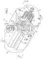
- FIG. 1 shows a partial cutaway view of the long life rack and pinion actuator 10 of the present invention.
- Actuator 10 comprises a housing 11 having an end cap 15 on one end and an end cap 15a on the opposite end.
- a rotatable shaft 16 having an upper and lower set of peripheral teeth 16a thereon.
- a piston extension rack 12a Located in meshing engagement with the teeth 16a is a piston extension rack 12a that extends outward from the face of piston 12.
- a set of springs 13 and 14 provide a stop for piston 12 when the piston is retracted.
- a bolt 20 having a stop end 22 and a nut 21 thereon provides for adjustment of stop end 22 which engages the back side of piston 12. While only one piston is shown in Figure 1 the actuator is symmetrical and includes a second piston on the opposite end of actuator 10.
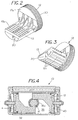
- Figure 2 shows an isolated top side perspective view of piston 12 with piston 12 having a cylindrical skirt 30 and an offset extension 13 that extends from face 12a of piston 12.
- extension 13 Located on extension 13 are a rack of teeth 13a for engaging the teeth 16a on rotateable shaft 16.
- Located on the lower side of extension 13 is a channel vent passage 20 to permit ingress and egress of fluid therethrough.
- Figure 3 shows an isolated bottom side perspective view of piston 12 revealing the channel passage 20 that extends longitudinally along the lower side of extension 13 as well as the integral elongated reinforcement ribs 13b for extensions 13.
- Figure 4 shows a cross sectional view taken along lines 4-4 of Figure 1 showing the piston 12 and piston 32 in engagement with teeth 16a on rotateable shaft 16.
- the piston 32 and piston 12 are identical to each other.
- actuator 10 In operation of actuator 10, if the pressure in piston end chamber 40 and piston end chamber 41 is greater than the pressure in central chamber 35 the pistons 12 and 32 are driven toward each other (indicated by arrows) thereby causing counter clockwise rotation of shaft 16 as the teeth on extension of each of the piston 12 and 32 engage the teeth 16a on the shaft and rotate the shaft 16. Similarly, if the pressure in the central chamber 35 is higher than the pressure in piston end chamber 40 and 41 the pistons are driven away from each other causing clockwise rotation of shaft 16 through engagement with the teeth 16a thereon. Thus through controlling the pressure in piston end chamber 40 and 41 as well as central chamber 35 one can drive pistons 12 and 32 back and forth within the cylindrical sidewalls 11a.
- Figure 5 is a cross sectional view taken along lines 5-5 of Figure 1 showing the piston 12 and 32 in relation to the shaft 16 which is rotateable mounted in housing 11.
- Piston 12 incudes a peripheral sealing and lubrication region 43 and similarly piston 32 includes a peripheral sealing and lubrication region 42.
- FIG. 5a shows the sliding region 42 of piston 32 in greater detail.
- Housing 11 has a cylindrical piston wall surface 11a for piston 32 to slide therealong.
- Recess 32a carries an annular wear member 51 to permit sliding engagement with wall surface 11a.
- recess 32c carries a wear member 52 to permit sliding engagement with wall surface 11a.
- recess 32c carries a resilient sealing member 53, such as an elastomer, to prevent flow therearound as well as resilient hold wear member 52 against wall 11a to allow piston 32 to slide laterally along cylindrical sealing wall 11a.
- the wear members 51 and 52 are made from a rigid wear material such as nylon or the like, which is softer than the cylindrical sealing wall 11a, yet sufficiently durable so as to be able to withstand repeated sliding engagement without having to be replaced.
- annular lubrication recess 32b for carrying a lubricant.
- a solid or viscous lubricant can be placed in the lubrication recess 32b to enable the lubrication to be carried on the piston skirt as the piston 32 slides back and forth thereby enabling the lubricant to be continually available proximate the wear members 51 and 52.
- the lubricant 70 which can be maintained in recess 32b is available for continual lubrication of the surface 11a so as to minimize wear as the piston 32 slides back and forth with the wear members 51 and 53 in sliding engagement with cylindrical wall surface 11a.
- Figure 6 shows a cross sectional view of actuator 10 showing the channel passage 20 is in fluid communication with a passage 11b in housing wall 11 to permit fluid to escape from the central chamber 35 as the pistons 12 and 32 move back and forth.
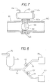
- FIG. 7 shows the actuator 10 of the present invention mounted on a rotatable valve such as a disk valve 63 found in a conveying system.
- a first conduit 61 is connected to conduit 60 with a disk valve 63 positioned in the passage.
- a shaft 62 carries disk valve 63 with shaft 62 having a top end 62a for engagement therotateable shaft 16 of the actuator 10.
- the lower end 62b provides for rotational support of the lower end of shaft 16.
- Actuator 10 is provide with fluid ports 10c and 10d which are connected to the chambers within actuator 10 so that the pistons 12 and 32 can be driven back and forth thereby causing rotation of shaft 16a which in turn rotates shaft 62 to open or close the passage from conduit 61 to conduit 62.
- the disk valve 63 is shown positioned in the open postion to allow flow of fluid past either side of disk 63. In order to close off the passage the disk 63 is rotated 90 degrees so that the disk 63 is perpendicular to the conduits 60 and 61.
- Figure 8 shows a system wherein a set of actuators 10 and 10' are connected to disk valves to permit diverting a material in the system.
- material is delivered to hopper 71 though conduit 72. The material then flows into pipe 73 and into branch pipes 74 and 75. If the valve to actuator 10 is in the open condition the material flows into bin 76 but if the valve is in the closed condition material is prevent from flowing into bin 76. Similarly, if the valve attached to actuator 10' is in the open condition the material flows into bin 77 but if the valve is in the closed condition material is prevent from flowing into bin 77.
- the invention includes a method for extending the cycle life of a rack and pinion actuator comprising the steps of forming at least two spaced apart wear member which are carried on a skirt of a piston for forming sliding engagement with a cylinder wall and placing an elastomer member proximate at least one of the spaced apart wear members to prevent flow of fluid therepast as well as to resiliently maintain the at least one of the spaced apart wear members in resilient contact with the cylinder wall.
- a non-runable lubricant such as viscous or solid lubricant between the spaced apart members one can provide for on-the-go lubrication of the wear members.
- the invention thus includes a conveying system with an actuator having a rotatable shaft and a set of pistons slidable in a cylinder, each of the pistons having a set of teeth for engaging with a set of teeth on the rotateable shaft so that displacement of the pistons toward or away from each other produces at least a partial rotation of the rotateable shaft.
- Each of the pistons has a skirt carrying a first wear member, a lubricant and a second wear member located on the skirt.
- an inner resilient or elastomer sealing member for preventing flow of fluidtherepast with lubricant carried therein maintaining a lubricated state between the cylinder and the wear member to allow for repeated displacement of the pistons without having to replace the sealing or the wear member.
Landscapes
- Engineering & Computer Science (AREA)
- Physics & Mathematics (AREA)
- Fluid Mechanics (AREA)
- Mechanical Engineering (AREA)
- General Engineering & Computer Science (AREA)
- Actuator (AREA)
- Valve Device For Special Equipments (AREA)
- Transmission Devices (AREA)
Applications Claiming Priority (2)
| Application Number | Priority Date | Filing Date | Title |
|---|---|---|---|
| US461892 | 1999-12-15 | ||
| US10/461,892 US6959913B2 (en) | 2003-06-13 | 2003-06-13 | Actuator |
Publications (1)
| Publication Number | Publication Date |
|---|---|
| EP1486680A1 true EP1486680A1 (fr) | 2004-12-15 |
Family
ID=33299875
Family Applications (1)
| Application Number | Title | Priority Date | Filing Date |
|---|---|---|---|
| EP20040012893 Withdrawn EP1486680A1 (fr) | 2003-06-13 | 2004-06-01 | Actionneur |
Country Status (7)
| Country | Link |
|---|---|
| US (2) | US6959913B2 (fr) |
| EP (1) | EP1486680A1 (fr) |
| JP (1) | JP4723819B2 (fr) |
| CN (1) | CN1573131A (fr) |
| BR (1) | BRPI0401473A (fr) |
| CA (1) | CA2461371C (fr) |
| TW (1) | TW200502498A (fr) |
Cited By (6)
| Publication number | Priority date | Publication date | Assignee | Title |
|---|---|---|---|---|
| EP2037145A3 (fr) * | 2007-09-14 | 2009-07-08 | ZF Friedrichshafen AG | Dispositif d'actionnement |
| EP2385284A1 (fr) * | 2010-05-04 | 2011-11-09 | ROTECH Antriebselemente GmbH | Mécanisme de commande pour une armature |
| FR2976983A1 (fr) * | 2011-06-27 | 2012-12-28 | Ksb Sas | Actionneur a quart tournant a pignon non cylindrique et cremaillere complementaire |
| WO2013068112A1 (fr) * | 2011-11-10 | 2013-05-16 | Schwing Gmbh | Structure de mât, destiné notamment à une pompe à béton automotrice, ainsi que pompe à béton automotrice |
| EP3290719A1 (fr) * | 2016-08-31 | 2018-03-07 | Goodrich Actuation Systems SAS | Agencement d'étanchéité pour un actionneur |
| IT201900015890A1 (it) * | 2019-09-09 | 2021-03-09 | C G M Srl | Dispositivo ribaltatore |
Families Citing this family (11)
| Publication number | Priority date | Publication date | Assignee | Title |
|---|---|---|---|---|
| CA2758970C (fr) * | 2009-04-27 | 2016-02-16 | Emerson Process Management Regulator Technologies, Inc. | Siege de ressort a auto-centrage pour regulateur de fluide et regulateur de fluide comprenant un siege de ressort a auto-centrage |
| US20130200285A1 (en) * | 2010-06-17 | 2013-08-08 | David Gent | Multi-teeth engagement in an actuator piston |
| CN201909093U (zh) * | 2010-12-22 | 2011-07-27 | 济南高仕机械制造有限公司 | 一种压缩气体单作用执行器 |
| US8747054B2 (en) | 2011-01-24 | 2014-06-10 | United Technologies Corporation | Bearing system for gas turbine engine |
| US9587454B1 (en) * | 2014-01-22 | 2017-03-07 | PacSeal Group, Inc. PacSeal | Modular actuator and hydraulic valve assemblies and control apparatus for oil well blow-out preventers |
| CN106687701B (zh) * | 2014-09-11 | 2019-02-15 | Smc株式会社 | 线性引导装置和致动器 |
| US10267429B2 (en) * | 2015-10-23 | 2019-04-23 | Magna Exteriors Inc. | Plastic injection mold—SVG actuator—internal seal upgrade |
| JP6460063B2 (ja) * | 2016-06-30 | 2019-01-30 | トヨタ自動車株式会社 | 電池 |
| US12036637B2 (en) * | 2018-04-24 | 2024-07-16 | Cold Jet, Llc | Particle blast apparatus |
| CN112459960B (zh) * | 2021-02-02 | 2021-04-13 | 湖南机电职业技术学院 | 一种液压伺服马达 |
| CN114352669A (zh) * | 2021-12-23 | 2022-04-15 | 中联重科股份有限公司 | 油气悬挂系统及其刚柔性控制阀和工程车辆 |
Citations (5)
| Publication number | Priority date | Publication date | Assignee | Title |
|---|---|---|---|---|
| FR1509067A (fr) * | 1966-11-29 | 1968-01-12 | Sud Aviation | Piston pour accumulateur hydraulique |
| EP0099546A1 (fr) * | 1982-07-21 | 1984-02-01 | AVA Steuerungstechnik GmbH | Entraînement rotatif |
| US4928577A (en) * | 1987-09-17 | 1990-05-29 | Kurt Stoll | Piston and cylinder unit |
| DE4411006A1 (de) * | 1993-06-17 | 1994-12-22 | Festo Kg | Führungs- und Dichtringkombination |
| US6173965B1 (en) * | 1998-12-28 | 2001-01-16 | Leopold J. Niessen | Actuator seal bearing assembly and method |
Family Cites Families (26)
| Publication number | Priority date | Publication date | Assignee | Title |
|---|---|---|---|---|
| US680465A (en) * | 1900-10-19 | 1901-08-13 | George H Reynolds | Piston. |
| JPS455303Y1 (fr) * | 1965-06-01 | 1970-03-13 | ||
| DE2103646A1 (de) * | 1971-01-27 | 1972-08-17 | Bosch Gmbh Robert | Arbeitszylinder |
| JPS499947A (fr) * | 1972-05-20 | 1974-01-29 | ||
| JPS5099389A (fr) * | 1973-12-28 | 1975-08-07 | ||
| US3994604A (en) * | 1975-06-30 | 1976-11-30 | Clark Equipment Company | Piston and rod connection |
| JPS54106504A (en) * | 1978-02-09 | 1979-08-21 | Agency Of Ind Science & Technol | System for coal gasification |
| US4214796A (en) * | 1978-10-19 | 1980-07-29 | General Electric Company | Bearing assembly with multiple squeeze film damper apparatus |
| JPS5687604A (en) * | 1979-12-05 | 1981-07-16 | Atomic Energy Authority Uk | Particle coating |
| JPS56117102A (en) * | 1980-02-20 | 1981-09-14 | Hitachi Ltd | Correcting method of noncontact thickness gauge |
| JPS5966064A (ja) * | 1982-10-05 | 1984-04-14 | Matsushita Electric Ind Co Ltd | 電池用ガス拡散電極の製造法 |
| JPS6015266A (ja) * | 1983-07-07 | 1985-01-25 | Atsugi Motor Parts Co Ltd | ラツク・ピニオン式ステアリング装置 |
| JPS60121560A (ja) * | 1983-12-02 | 1985-06-29 | Matsushita Electric Ind Co Ltd | 磁気記録再生装置 |
| JPS60139959A (ja) * | 1983-12-27 | 1985-07-24 | Honda Motor Co Ltd | 自動変速機の制御方法 |
| JPS61119607A (ja) * | 1984-11-16 | 1986-06-06 | Kawasaki Steel Corp | 高炉操業法 |
| DE3534577C2 (de) * | 1985-09-27 | 1993-11-18 | Atsugi Motor Parts Co Ltd | Hydraulische Zahnstangenhilfskraftlenkung |
| JPS63118404A (ja) * | 1986-11-04 | 1988-05-23 | シビル環境エンジニヤリング株式会社 | 屋外用防音壁工法 |
| JPS6414903A (en) * | 1987-07-08 | 1989-01-19 | Kanegafuchi Chemical Ind | Resin-bound permanent magnet |
| US4890645A (en) * | 1987-10-08 | 1990-01-02 | Baroid Technology, Inc. | Rotary shear seal hydraulic valve |
| JPH0292106A (ja) * | 1988-09-29 | 1990-03-30 | Nec Corp | 自動利得制御回路 |
| JPH0369759A (ja) * | 1989-08-07 | 1991-03-26 | Sukemasa Umeda | コーキング無しの外壁パネル貼り |
| JPH0434203A (ja) * | 1990-05-31 | 1992-02-05 | T V Valve Kk | ピストン型揺動アクチュエータ |
| JPH0452658A (ja) * | 1990-06-21 | 1992-02-20 | Toshiba Corp | 画像形成装置 |
| JPH08145186A (ja) * | 1994-11-18 | 1996-06-04 | Nok Corp | シ−ル装置 |
| JP2003278712A (ja) * | 2002-01-16 | 2003-10-02 | S N Seiki:Kk | エア式アクチュエータとその製造方法 |
| JP4376780B2 (ja) * | 2002-06-14 | 2009-12-02 | 株式会社キッツ | 空気圧アクチュエータ |
-
2003
- 2003-06-13 US US10/461,892 patent/US6959913B2/en not_active Expired - Lifetime
-
2004
- 2004-03-18 TW TW093107232A patent/TW200502498A/zh unknown
- 2004-03-19 CA CA 2461371 patent/CA2461371C/fr not_active Expired - Fee Related
- 2004-04-20 BR BRPI0401473 patent/BRPI0401473A/pt not_active Application Discontinuation
- 2004-05-12 JP JP2004141813A patent/JP4723819B2/ja not_active Expired - Fee Related
- 2004-06-01 CN CNA2004100473571A patent/CN1573131A/zh active Pending
- 2004-06-01 EP EP20040012893 patent/EP1486680A1/fr not_active Withdrawn
-
2005
- 2005-08-11 US US11/201,589 patent/US7111823B2/en not_active Expired - Lifetime
Patent Citations (5)
| Publication number | Priority date | Publication date | Assignee | Title |
|---|---|---|---|---|
| FR1509067A (fr) * | 1966-11-29 | 1968-01-12 | Sud Aviation | Piston pour accumulateur hydraulique |
| EP0099546A1 (fr) * | 1982-07-21 | 1984-02-01 | AVA Steuerungstechnik GmbH | Entraînement rotatif |
| US4928577A (en) * | 1987-09-17 | 1990-05-29 | Kurt Stoll | Piston and cylinder unit |
| DE4411006A1 (de) * | 1993-06-17 | 1994-12-22 | Festo Kg | Führungs- und Dichtringkombination |
| US6173965B1 (en) * | 1998-12-28 | 2001-01-16 | Leopold J. Niessen | Actuator seal bearing assembly and method |
Cited By (14)
| Publication number | Priority date | Publication date | Assignee | Title |
|---|---|---|---|---|
| EP2037145A3 (fr) * | 2007-09-14 | 2009-07-08 | ZF Friedrichshafen AG | Dispositif d'actionnement |
| EP2385284A1 (fr) * | 2010-05-04 | 2011-11-09 | ROTECH Antriebselemente GmbH | Mécanisme de commande pour une armature |
| FR2976983A1 (fr) * | 2011-06-27 | 2012-12-28 | Ksb Sas | Actionneur a quart tournant a pignon non cylindrique et cremaillere complementaire |
| WO2013001173A1 (fr) | 2011-06-27 | 2013-01-03 | Ksb S.A.S. | Actionneur a quart tournant a pignon non cylindrique et cremaillere complementaire |
| WO2013068112A1 (fr) * | 2011-11-10 | 2013-05-16 | Schwing Gmbh | Structure de mât, destiné notamment à une pompe à béton automotrice, ainsi que pompe à béton automotrice |
| CN103998368A (zh) * | 2011-11-10 | 2014-08-20 | 施维英有限公司 | 尤其用于车载式混凝土泵的臂架结构以及车载式混凝土泵 |
| EP2776360B1 (fr) | 2011-11-10 | 2016-02-03 | Schwing GmbH | Structure de mât, destiné notamment à une pompe à béton automotrice, ainsi que pompe à béton automotrice |
| CN103998368B (zh) * | 2011-11-10 | 2016-06-08 | 施维英有限公司 | 尤其用于车载式混凝土泵的臂架结构以及车载式混凝土泵 |
| CN105947909A (zh) * | 2011-11-10 | 2016-09-21 | 施维英有限公司 | 臂架结构以及车载式混凝土泵 |
| US9453351B2 (en) | 2011-11-10 | 2016-09-27 | Schwing Gmbh | Boom construction for a truck-mounted concrete pump |
| EP3290719A1 (fr) * | 2016-08-31 | 2018-03-07 | Goodrich Actuation Systems SAS | Agencement d'étanchéité pour un actionneur |
| EP3290719B1 (fr) | 2016-08-31 | 2019-07-17 | Goodrich Actuation Systems SAS | Agencement d'étanchéité pour un actionneur |
| IT201900015890A1 (it) * | 2019-09-09 | 2021-03-09 | C G M Srl | Dispositivo ribaltatore |
| WO2021048737A1 (fr) * | 2019-09-09 | 2021-03-18 | C.G.M. Srl | Dispositif d'inclinaison |
Also Published As
| Publication number | Publication date |
|---|---|
| US6959913B2 (en) | 2005-11-01 |
| US7111823B2 (en) | 2006-09-26 |
| US20050274919A1 (en) | 2005-12-15 |
| CA2461371A1 (fr) | 2004-12-13 |
| TW200502498A (en) | 2005-01-16 |
| CA2461371C (fr) | 2011-09-13 |
| JP4723819B2 (ja) | 2011-07-13 |
| CN1573131A (zh) | 2005-02-02 |
| BRPI0401473A (pt) | 2005-01-18 |
| US20040251445A1 (en) | 2004-12-16 |
| JP2005003196A (ja) | 2005-01-06 |
Similar Documents
| Publication | Publication Date | Title |
|---|---|---|
| US6959913B2 (en) | Actuator | |
| RU2717590C2 (ru) | Система уплотнения сжатым газом для регулирующих клапанов | |
| US9897217B2 (en) | Low-drag sealing method for thermal management valve | |
| US20170067565A1 (en) | Valve apparatus for vehicle | |
| US8926298B2 (en) | Hydraulic piston pump with a variable displacement throttle mechanism | |
| US10107337B2 (en) | Bearing assembly | |
| CN102333979B (zh) | 具有润滑辅助密封件的闸门阀 | |
| US5800136A (en) | Pump with bypass valve | |
| US20030041598A1 (en) | Double racks and pinion type rotary actuator | |
| CA2019839C (fr) | Regulateur pneumatique de niveau d'huile de transmission | |
| US20130248035A1 (en) | Diverter Valve | |
| JP2019065757A (ja) | プランジャポンプ | |
| CA2509996C (fr) | Dispositif a soupape et pompe a diaphragme a entrainement pneumatique ainsi equipee | |
| CN1302964A (zh) | 二通换向阀 | |
| US7694939B2 (en) | Flow rate control valve | |
| US11536375B2 (en) | Valve seat with seal for use with valve element in valve assembly | |
| CN110319243A (zh) | 控制阀 | |
| US11965597B2 (en) | Piston assembly, air cylinder and apparatus for processing substrate | |
| KR19980087396A (ko) | 에어레이터 밸브어셈블리 | |
| US557285A (en) | pearn | |
| US6981854B1 (en) | Small piston pump | |
| US637487A (en) | Annular slide-valve. | |
| US20040184939A1 (en) | Feed pump | |
| JP2517209Y2 (ja) | 流体切換弁 | |
| CN114110399A (zh) | 润滑剂泵 |
Legal Events
| Date | Code | Title | Description |
|---|---|---|---|
| PUAI | Public reference made under article 153(3) epc to a published international application that has entered the european phase |
Free format text: ORIGINAL CODE: 0009012 |
|
| AK | Designated contracting states |
Kind code of ref document: A1 Designated state(s): AT BE BG CH CY CZ DE DK EE ES FI FR GB GR HU IE IT LI LU MC NL PL PT RO SE SI SK TR |
|
| AX | Request for extension of the european patent |
Extension state: AL HR LT LV MK |
|
| 17P | Request for examination filed |
Effective date: 20050504 |
|
| 17Q | First examination report despatched |
Effective date: 20050620 |
|
| AKX | Designation fees paid |
Designated state(s): AT BE BG CH CY CZ DE DK EE ES FI FR GB GR HU IE IT LI LU MC NL PL PT RO SE SI SK TR |
|
| GRAP | Despatch of communication of intention to grant a patent |
Free format text: ORIGINAL CODE: EPIDOSNIGR1 |
|
| STAA | Information on the status of an ep patent application or granted ep patent |
Free format text: STATUS: THE APPLICATION IS DEEMED TO BE WITHDRAWN |
|
| 18D | Application deemed to be withdrawn |
Effective date: 20070116 |