EP1486729A1 - Verbrennungsofen - Google Patents
Verbrennungsofen Download PDFInfo
- Publication number
- EP1486729A1 EP1486729A1 EP03701746A EP03701746A EP1486729A1 EP 1486729 A1 EP1486729 A1 EP 1486729A1 EP 03701746 A EP03701746 A EP 03701746A EP 03701746 A EP03701746 A EP 03701746A EP 1486729 A1 EP1486729 A1 EP 1486729A1
- Authority
- EP
- European Patent Office
- Prior art keywords
- combustion
- combustion chamber
- promoting fluid
- steam
- air
- Prior art date
- Legal status (The legal status is an assumption and is not a legal conclusion. Google has not performed a legal analysis and makes no representation as to the accuracy of the status listed.)
- Granted
Links
Images


Classifications
-
- F—MECHANICAL ENGINEERING; LIGHTING; HEATING; WEAPONS; BLASTING
- F23—COMBUSTION APPARATUS; COMBUSTION PROCESSES
- F23C—METHODS OR APPARATUS FOR COMBUSTION USING FLUID FUEL OR SOLID FUEL SUSPENDED IN A CARRIER GAS OR AIR
- F23C5/00—Disposition of burners with respect to the combustion chamber or to one another; Mounting of burners in combustion apparatus
- F23C5/08—Disposition of burners
- F23C5/32—Disposition of burners to obtain rotating flames, i.e. flames moving helically or spirally
-
- F—MECHANICAL ENGINEERING; LIGHTING; HEATING; WEAPONS; BLASTING
- F23—COMBUSTION APPARATUS; COMBUSTION PROCESSES
- F23G—CREMATION FURNACES; CONSUMING WASTE PRODUCTS BY COMBUSTION
- F23G5/00—Incineration of waste; Incinerator constructions; Details, accessories or control therefor
- F23G5/08—Incineration of waste; Incinerator constructions; Details, accessories or control therefor having supplementary heating
- F23G5/12—Incineration of waste; Incinerator constructions; Details, accessories or control therefor having supplementary heating using gaseous or liquid fuel
-
- F—MECHANICAL ENGINEERING; LIGHTING; HEATING; WEAPONS; BLASTING
- F23—COMBUSTION APPARATUS; COMBUSTION PROCESSES
- F23G—CREMATION FURNACES; CONSUMING WASTE PRODUCTS BY COMBUSTION
- F23G5/00—Incineration of waste; Incinerator constructions; Details, accessories or control therefor
- F23G5/32—Incineration of waste; Incinerator constructions; Details, accessories or control therefor the waste being subjected to a whirling movement, e.g. cyclonic incinerators
-
- F—MECHANICAL ENGINEERING; LIGHTING; HEATING; WEAPONS; BLASTING
- F23—COMBUSTION APPARATUS; COMBUSTION PROCESSES
- F23G—CREMATION FURNACES; CONSUMING WASTE PRODUCTS BY COMBUSTION
- F23G5/00—Incineration of waste; Incinerator constructions; Details, accessories or control therefor
- F23G5/44—Details; Accessories
-
- F—MECHANICAL ENGINEERING; LIGHTING; HEATING; WEAPONS; BLASTING
- F23—COMBUSTION APPARATUS; COMBUSTION PROCESSES
- F23L—SUPPLYING AIR OR NON-COMBUSTIBLE LIQUIDS OR GASES TO COMBUSTION APPARATUS IN GENERAL ; VALVES OR DAMPERS SPECIALLY ADAPTED FOR CONTROLLING AIR SUPPLY OR DRAUGHT IN COMBUSTION APPARATUS; INDUCING DRAUGHT IN COMBUSTION APPARATUS; TOPS FOR CHIMNEYS OR VENTILATING SHAFTS; TERMINALS FOR FLUES
- F23L1/00—Passages or apertures for delivering primary air for combustion
-
- F—MECHANICAL ENGINEERING; LIGHTING; HEATING; WEAPONS; BLASTING
- F23—COMBUSTION APPARATUS; COMBUSTION PROCESSES
- F23L—SUPPLYING AIR OR NON-COMBUSTIBLE LIQUIDS OR GASES TO COMBUSTION APPARATUS IN GENERAL ; VALVES OR DAMPERS SPECIALLY ADAPTED FOR CONTROLLING AIR SUPPLY OR DRAUGHT IN COMBUSTION APPARATUS; INDUCING DRAUGHT IN COMBUSTION APPARATUS; TOPS FOR CHIMNEYS OR VENTILATING SHAFTS; TERMINALS FOR FLUES
- F23L7/00—Supplying non-combustible liquids or gases, other than air, to the fire, e.g. oxygen, steam
- F23L7/002—Supplying water
- F23L7/005—Evaporated water; Steam
-
- F—MECHANICAL ENGINEERING; LIGHTING; HEATING; WEAPONS; BLASTING
- F23—COMBUSTION APPARATUS; COMBUSTION PROCESSES
- F23L—SUPPLYING AIR OR NON-COMBUSTIBLE LIQUIDS OR GASES TO COMBUSTION APPARATUS IN GENERAL ; VALVES OR DAMPERS SPECIALLY ADAPTED FOR CONTROLLING AIR SUPPLY OR DRAUGHT IN COMBUSTION APPARATUS; INDUCING DRAUGHT IN COMBUSTION APPARATUS; TOPS FOR CHIMNEYS OR VENTILATING SHAFTS; TERMINALS FOR FLUES
- F23L9/00—Passages or apertures for delivering secondary air for completing combustion of fuel
- F23L9/06—Passages or apertures for delivering secondary air for completing combustion of fuel by discharging the air into the fire bed
-
- F—MECHANICAL ENGINEERING; LIGHTING; HEATING; WEAPONS; BLASTING
- F23—COMBUSTION APPARATUS; COMBUSTION PROCESSES
- F23L—SUPPLYING AIR OR NON-COMBUSTIBLE LIQUIDS OR GASES TO COMBUSTION APPARATUS IN GENERAL ; VALVES OR DAMPERS SPECIALLY ADAPTED FOR CONTROLLING AIR SUPPLY OR DRAUGHT IN COMBUSTION APPARATUS; INDUCING DRAUGHT IN COMBUSTION APPARATUS; TOPS FOR CHIMNEYS OR VENTILATING SHAFTS; TERMINALS FOR FLUES
- F23L2900/00—Special arrangements for supplying or treating air or oxidant for combustion; Injecting inert gas, water or steam into the combustion chamber
- F23L2900/07008—Injection of water into the combustion chamber
-
- F—MECHANICAL ENGINEERING; LIGHTING; HEATING; WEAPONS; BLASTING
- F23—COMBUSTION APPARATUS; COMBUSTION PROCESSES
- F23L—SUPPLYING AIR OR NON-COMBUSTIBLE LIQUIDS OR GASES TO COMBUSTION APPARATUS IN GENERAL ; VALVES OR DAMPERS SPECIALLY ADAPTED FOR CONTROLLING AIR SUPPLY OR DRAUGHT IN COMBUSTION APPARATUS; INDUCING DRAUGHT IN COMBUSTION APPARATUS; TOPS FOR CHIMNEYS OR VENTILATING SHAFTS; TERMINALS FOR FLUES
- F23L2900/00—Special arrangements for supplying or treating air or oxidant for combustion; Injecting inert gas, water or steam into the combustion chamber
- F23L2900/07009—Injection of steam into the combustion chamber
Definitions
- the present invention relates to an incinerator, and more particularly to an incinerator which incinerates industrial waste and other varieties of waste, for example.
- a lateral section of one of the upper and lower horizontal portion of each of the air-supply pipes is provided with a plurality of air nozzles, through which a high-pressure, high-temperature air is blown out in the circumferential direction of the combustion chamber.
- a swirling flow is generated within the combustion chamber by blowing out high-pressure, high-temperature air in the circumferential direction of the combustion chamber together with supplying oxygen, so that combustion efficiency is raised and also the generation of non-combusted components is curbed.
- an object of the present invention is to provide a high-performance incinerator capable of raising combustion efficiency for various wastes and curbing as much as possible the generation of non-combusted components and the like.
- An incinerator of the present invention comprises a cylindrical combustion chamber; and a plurality of combustion-promoting blast pipes each of which is disposed so as to project from one location on an inner wall of the combustion chamber, extend in a vertical direction thereof and exit to exterior from another location, wherein the combustion-promoting fluid blast pipes are of a triple-pipe construction, comprising an air-supply pipe, a steam/gas-supply pipe which is provided concentrically outside of the air-supply pipe for supplying steam or combustible gas, and a water pipe which is provided concentrically further outside thereof for protecting the air-supply pipe and the steam/gas-supply pipe from heat, a plurality of nozzles being provided on each of the combustion-promoting fluid blast pipes, and the nozzles being positioned facing in one circumferential direction of the combustion chamber so that a combustion-promoting fluid blown out from the combustion-promoting fluid blast pipes forms a swirling flow within the combustion chamber; and the air-supply pipes and the steam/gas-supply pipes in the combustion-promoting fluid blast pipes
- the incinerator of the present invention comprises a cylindrical combustion chamber; and a plurality of combustion-promoting blast pipes each of which is disposed so as to project from an inner wall of the combustion chamber and extend in a vertical direction thereof, wherein the combustion-promoting fluid blast pipes are of a quadruple-pipe construction, comprising an air-supply pipe, a steam-supply pipe which is provided concentrically outside of the air-supply pipe, a combustible-gas supply pipe provided concentrically outside of the steam-supply pipe, and a water pipe which is provided concentrically further outside thereof for protecting the air-supply pipe, the steam-supply pipe and the combustible-gas supply pipe from heat, a plurality of nozzles being provided on each of the combustion-promoting fluid blast pipes, the nozzles being positioned facing in one circumferential direction of the combustion chamber so that a combustion-promoting fluid blown out from the combustion-promoting fluid blast pipes forms a swirling flow within the combustion chamber; and the air-supply pipes, the steam-suppl
- the combustion-promoting fluid blast pipes provided within the combustion chamber may project from the inner wall of the combustion chamber in a radial direction.
- they may be disposed on respective sides of a hypothetical polygon inscribed in the combustion chamber when the combustion chamber is viewed in a transverse cross section.
- the hypothetical polygon inscribed in the combustion chamber is a regular tetragon, which defines the installation position of the combustion-promoting fluid blast pipes.
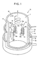
- FIG. 1 the lower section of an incinerator 10 according to one embodiment of the present invention is shown as a principal component.
- This incinerator 10 comprises a cylindrical combustion chamber 11 formed therein by an inner wall 12. On the outside of the inner wall 12 an outer wall 13 is provided. A water jacket 14 is formed between the inner wall 12 and the outer wall 13.
- a jacket compartment wall 15 is provided which encloses the perimeter of this outer wall 13.
- Another jacket compartment wall 16 is provided further outside thereof
- the jacket formed by the outer wall 13 and the jacket compartment wall 15 forms a steam/gas chamber 17, which houses a gas having a high vaporization temperature such as PCB or the like, or steam, or a mixed fluid thereof, and the jacket further outside thereof forms an air chamber 18.
- combustion-promoting fluid blast pipes 19 are installed in the combustion chamber 11 of this incinerator 10, as is shown in Fig. 1 and Fig. 2, four combustion-promoting fluid blast pipes 19 are installed. These combustion-promoting fluid blast pipes 19 are provided in an approximate U-shape by a horizontal pipe portion 19a which projects approximately horizontally from one part of the wall section demarcating the combustion chamber 11, a vertical pipe portion 19c which extends in the vertical direction of the combustion chamber 11, and a horizontal pipe portion 19b which exits to the exterior from another part of the wall section.
- each combustion-promoting fluid blast pipe 19 has an air-supply pipe 20a disposed in the innermost side, a steam/gas-supply pipe disposed concentrically outside thereof, and a water pipe 20c disposed concentrically further outside thereof.
- the air-supply pipe 20a of the innermost side communicates with the air chamber 18, and the steam/gas-supply pipe 20b outside thereof communicates with the steam/gas chamber 17, and the outermost water pipe 20c is in communication with the water jacket 14.
- the water jacket 14 of the incinerator 10 is in communication with a water-supply source, not shown, and furthermore this water jacket 14 is connected with the steam/gas chamber 17 by a communication pipe, via a steam heater (not shown) provided in the upper section of the combustion chamber 11.
- a first switching valve (not shown) is provided on the communication pipe supplying high-temperature water vapor from the steam heater to the steam/gas chamber 17, and by controlling this first switching valve a supply of steam can be received, or alternatively the supply of steam can be suspended.
- the communication pipe is constructed so that in a case where the first switching valve is closed, a safety valve such as a relief valve operates concurrently.
- this steam/gas chamber 17 is also connected to a polychlorinated biphenyl (PCB)-supply source, not shown, by a communication pipe.
- PCB-supply source is connected by a communication pipe to a downstream passage section of a PCB heater installed within the combustion chamber 11, and the upstream passage section of this PCB heater is in communication with the steam/gas chamber 17 by a communication pipe.
- a second switching valve (not shown) is installed on the communication pipe which sends PCB from the PCB-supply source to the PCB heater, and by controlling this second switching valve PCB can be supplied or alternatively, the supply can be suspended.
- the PCB sent from the PCB-supply source to the PCB heater is heated and vaporized (gasified) by the combustion heat within the combustion chamber 11.
- PCB vaporizes at approximately 603-648 degrees Celsius, to become a combustible gas.
- a combustible gas of vaporized PCB is supplied to the steam/gas chamber 17 and is mixed with water vapor, or taken in alone.
- the PCB gas that has been taken into the steam/gas chamber 17 mixed with water vapor or alone is blown out into the combustion chamber 11 via the combustion-promoting fluid blast pipes 19, together with high-temperature, high-pressure air.
- PCB has been burnt at a high temperature of approximately 1,200 degrees Celsius, and has incurred expenses such as fuel costs and electricity costs.
- the incinerator 10 which incinerates industrial waste and the like in the way as described above, when the combustion heat which develops within the combustion chamber 11 is utilized to heat and vaporize the PCB, the PCB can be burnt as a fuel even at low temperatures, and furthermore, dioxin and other toxic substances do not develop during incineration. Therefore, an extremely advantageous and economical processing method is provided by the present invention.
- the air chamber 18 is in communication with a high-pressure air-supply source, not shown, and is supplied with high-pressure air from this high-pressure air-supply source.
- the high-pressure air supplied from the high-pressure air-supply source is sent to an air-heating device (not shown) installed within the upper part of the combustion chamber 11, and after being heated therein is supplied to the air chamber 18.
- a plurality of combustion-promoting fluid nozzles 21 is provided formed in a line with each oriented in a circumferential direction, in positions closer to the core and positions closer to the inner wall 12.
- Each combustion-promoting fluid nozzle 21 has an air nozzle 21a disposed in the center, and a steam/gas-supply nozzle 21b disposed concentrically outside thereof
- the air nozzle 21a of the central side is provided so as to communicate with the air-supply pipe 20a, and the ring-shaped steam/gas nozzle 21b outside thereof is provided so as to communicate with the gas/steam supply pipe 20b.
- a cap 22 is fitted at the front of each of the combustion-promoting fluid nozzles 21, in which the air nozzles 21 a and the steam/gas nozzles 21b are concentrically provided.
- This cap 22 as shown in Fig. 4, is provided in the central section thereof with a circular opening 22a having the same diameter as the air nozzle 21 a, and on the perimeter of this circular opening 22a, namely, in the annular section blocking steam/gas nozzle 21b, a multiplicity of circular openings 22b is provided in a line, equidistantly spaced.
- the combustion-promoting fluid consisting of high-pressure, high-temperature air and PCB gas or steam or a mixed fluid thereof, which is blown out from each of the combustion-promoting fluid nozzles 21 of each of the combustion-promoting fluid blast pipes 19, mixes evenly immediately after being blown out because the high-pressure, high-temperature air is blown out from the opening 22a in the central section of the cap 22 and the PCB gas or steam or mixed fluid thereof is blown out from the plurality of openings 22b on the perimeter thereof
- combustion promoting fluid which is blown out from each of the combustion-promoting fluid nozzles 21 of the combustion-promoting fluid blast pipes 19, which face in the circumferential direction of the combustion chamber 11 and are adjacent to the inner wall 12 therein, generates a swirling flow within the combustion chamber 11, as is illustrated by the arrow 23 in Fig. 1.
- the blowing out of the combustion-promoting fluid to form a swirling flow in this way becomes one major factor facilitating the incineration of industrial and other varieties of waste.
- the high-pressure, high-temperature air which is blown out from the air nozzles 2 1 a via the air-supply pipe 20a is heated by the air-heating pipe in the upper section of the combustion chamber 11, and so does not bring about a reduction in the furnace temperature when supplied to the combustion chamber 11.
- the combustion-promoting fluid blown out from each of the combustion-promoting fluid nozzles 21 becomes a large vortex swirling in the entire combustion chamber 11, so that the combustion effect is markedly improved.
- water vapor is heated by the steam heater provided in the upper section of the combustion chamber 11, and when this is blown out into the combustion chamber 11 from the combustion-promoting fluid nozzles 21 together with the high-pressure, high-temperature air, the combustion effect can be increased with the action of the water vapor. Namely, by mixing water vapor in the high-pressure, high-temperature air blown out from the air-supply pipe 20a, combustibility increases, and combustion is promoted further.
- high-pressure, high-temperature air is supplied to the combustion chamber 11 in order to utilize the oxygen contained in air in a proportion of a little less than 21%, as a combustion improver, while the oxygen content of steam vapor, namely water, is a little more than 33%. Accordingly, a better combustion efficiency is achieved burning materials by supplying water, with an oxygen content of a little more than 33%, than by burning materials using air, with an oxygen content of a little less than 21%.
- water itself will not bum in a normal state, and is required to be burnt under high-temperature conditions which separate the water into hydrogen and oxygen.
- even if burning with steam is recognized as providing a better combustion efficiency, because steam does not develop from immediately after the inception of combustion, it is necessary to supply high-pressure, high-temperature air simultaneously.
- control devices are employed so that the supply of air to the combustion chamber 11, and the supply to the combustion chamber 11 of either combustible gas or steam or both to the combustion chamber 11 are conducted separately, and therefore high-pressure, high-temperature air and heated water vapor can be supplied to the combustion chamber 11 in desirably balanced quantities.
- this incinerator 10 supplying only high-pressure, high-temperature air, supplying only steam, supplying only combustible (PCB) gas, or supplying an appropriate combination thereof to the combustion chamber 11 is made all possible.
- combustion efficiency can be increased by elevating the furnace temperature to a high temperature easily, or phrased differently, by controlling the furnace temperature at a high temperature easily.
- this incinerator 10 due to a unique construction which gives protection to the air-supply pipe 20a and the steam/gas-supply pipe 20b with the water pipe 20c, and also gives protection to the water pipe 20c itself with the water flowing inside thereof from extreme temperature increases, there is no occurrence of heat degradation whatsoever, and accordingly there is no damage caused by the impact of introducing industrial and other varieties of waste.
- the combustion-promoting fluid blast pipes 19 are installed within this combustion chamber 11 so as to be positioned on the respective sides of a regular tetragon inscribed therein.
- the present invention is not limited to this mode of arrangement and it is also acceptable to position the combustion-promoting fluid blast pipes 19 to as to project radially from the wall of the incinerator, as in conventional incinerators.
- each of the combustion-promoting fluid blast pipes 19 are given a triple-pipe construction.
- a quadruple-pipe construction is also desirable.
- each of the combustion-promoting fluid blast pipes 19 may be constituted by an air-supply pipe disposed in the innermost side, a steam-supply pipe disposed outside thereof, a PCB gas (combustible gas)-supply pipe disposed further outside thereof, and a water pipe on the outermost side.
- a part of the water jacket 14 in the incinerator 10 according to the above-mentioned embodiment is further divided into two jackets, and the inner jacket is made exclusively for PCB gas, and the jacket outside thereof is made exclusively for water.
- combustion-promoting fluid blast pipes of a triple-pipe construction or a quadruple-pipe construction are provided inside the combustion chamber, and by making it possible to blow out a combustion-promoting fluid consisting of air and either steam or combustible gas or both from these combustion-promoting fluid blast pipes so that a swirling flow develops within the combustion chamber, whereby not only can combustion efficiency be increased when waste and the like is incinerated for example, but the generation of harmful gases can also be contained, and processing capacity can be raised markedly.
- an incinerator of the present invention is suitable as an incinerator that, when industrial and other varieties of waste are incinerated, increases combustion efficiency while controlling the generation of harmful gases, and furthermore, markedly increases the processing capacity.
Landscapes
- Engineering & Computer Science (AREA)
- Mechanical Engineering (AREA)
- General Engineering & Computer Science (AREA)
- Chemical & Material Sciences (AREA)
- Combustion & Propulsion (AREA)
- Gasification And Melting Of Waste (AREA)
- Incineration Of Waste (AREA)
- Air Supply (AREA)
- Crucibles And Fluidized-Bed Furnaces (AREA)
- Furnace Details (AREA)
- Treatment Of Sludge (AREA)
Applications Claiming Priority (3)
| Application Number | Priority Date | Filing Date | Title |
|---|---|---|---|
| JP2002066497 | 2002-03-12 | ||
| JP2002066497 | 2002-03-12 | ||
| PCT/JP2003/000323 WO2003076847A1 (fr) | 2002-03-12 | 2003-01-16 | Incinerateur |
Publications (3)
| Publication Number | Publication Date |
|---|---|
| EP1486729A1 true EP1486729A1 (de) | 2004-12-15 |
| EP1486729A4 EP1486729A4 (de) | 2007-07-11 |
| EP1486729B1 EP1486729B1 (de) | 2011-03-16 |
Family
ID=27800253
Family Applications (1)
| Application Number | Title | Priority Date | Filing Date |
|---|---|---|---|
| EP03701746A Expired - Lifetime EP1486729B1 (de) | 2002-03-12 | 2003-01-16 | Verbrennungsofen |
Country Status (9)
| Country | Link |
|---|---|
| US (1) | US6976439B2 (de) |
| EP (1) | EP1486729B1 (de) |
| JP (1) | JP4148363B2 (de) |
| AT (1) | ATE502255T1 (de) |
| AU (1) | AU2003203238B2 (de) |
| CA (1) | CA2478672C (de) |
| DE (1) | DE60336384D1 (de) |
| MY (1) | MY134461A (de) |
| WO (1) | WO2003076847A1 (de) |
Cited By (3)
| Publication number | Priority date | Publication date | Assignee | Title |
|---|---|---|---|---|
| CH711812A1 (fr) * | 2015-11-26 | 2017-05-31 | Carboforce Sàrl | Brûleur. |
| WO2019215351A1 (es) | 2018-05-07 | 2019-11-14 | CALISALVO DURAN, Luis | Oxidador catalítico |
| SE2250636A1 (en) * | 2022-05-27 | 2023-11-28 | Ecomb Ab | Tubular supply device |
Families Citing this family (13)
| Publication number | Priority date | Publication date | Assignee | Title |
|---|---|---|---|---|
| US7720707B1 (en) | 2000-01-07 | 2010-05-18 | Home Producers Network, Llc | Method and system for compiling a consumer-based electronic database, searchable according to individual internet user-defined micro-demographics |
| US8214254B1 (en) | 2000-01-07 | 2012-07-03 | Home Producers Network, Llc | Method and system for compiling a consumer-based electronic database, searchable according to individual internet user-defined micro-demographics (II) |
| CH699405B1 (de) * | 2008-08-26 | 2021-06-15 | Mokesys Ag | Feuerfeste Wand, insbesondere für einen Verbrennungsofen. |
| JP2011208880A (ja) * | 2010-03-30 | 2011-10-20 | Shinnetsu Kogyo Kk | 加熱処理装置 |
| CN103453529A (zh) * | 2013-09-26 | 2013-12-18 | 内蒙古日清源环保科技有限责任公司 | 焚烧炉 |
| US11982442B2 (en) * | 2015-02-27 | 2024-05-14 | Morgan State University | System and method for biomass combustion |
| KR200479628Y1 (ko) * | 2015-09-24 | 2016-02-18 | 김성국 | 증기를 이용한 가열장치 |
| CN106931446A (zh) * | 2015-12-31 | 2017-07-07 | 未名生物环保集团有限公司 | 垃圾高效环保热解装置 |
| KR101880160B1 (ko) * | 2016-08-25 | 2018-07-20 | 김병태 | 폐기물 소각용 보일러장치 |
| WO2018052337A1 (ru) * | 2016-09-15 | 2018-03-22 | Марк СОЛОНИН | Пиролизный котел |
| CN109028089A (zh) * | 2018-07-05 | 2018-12-18 | 杭州桥福科技有限公司 | 一种环保型天然气垃圾焚烧炉 |
| AU2019432235B2 (en) * | 2019-03-05 | 2024-02-01 | Questor Technology Inc. | Gas incinerator system |
| CN113375166A (zh) * | 2021-05-28 | 2021-09-10 | 北京基亚特环保科技有限公司 | 一种焚烧垃圾用布料布气装置 |
Family Cites Families (10)
| Publication number | Priority date | Publication date | Assignee | Title |
|---|---|---|---|---|
| US754151A (en) * | 1903-09-21 | 1904-03-08 | Edward R Lewis | Device for aiding combustion in boiler-furnaces. |
| US1721782A (en) * | 1925-06-13 | 1929-07-23 | Firm Ignis A G | Furnace for steam boilers |
| FR1208469A (fr) * | 1957-06-11 | 1960-02-24 | Dingler Ets | Installation pour foyers pour la combustion en plusieurs phases de combustibles solides |
| US3771469A (en) * | 1972-08-09 | 1973-11-13 | Gen Electric | Incinerator |
| JPS50127472A (de) * | 1974-03-25 | 1975-10-07 | ||
| JPS54121425A (en) * | 1978-03-13 | 1979-09-20 | Babcock Hitachi Kk | Duct burner |
| JP2543673Y2 (ja) * | 1991-03-19 | 1997-08-13 | 株式会社大東 | 小型焼却炉 |
| JPH11282888A (ja) * | 1998-03-26 | 1999-10-15 | Omron Corp | システム仕様記述に基づいて設計されるシステムでのデータ通信方法、割込コントローラ合成方法及びインターフェイス回路合成方法 |
| JP3415079B2 (ja) * | 1999-10-04 | 2003-06-09 | 要太郎 内田 | 焼却炉 |
| FR2802616B1 (fr) * | 1999-12-16 | 2002-02-08 | Inst Francais Du Petrole | Methode et dispositif d'auto-combustion de dechets organiques graisseux comportant un foyer a chauffe tangentielle |
-
2003
- 2003-01-16 US US10/507,338 patent/US6976439B2/en not_active Expired - Fee Related
- 2003-01-16 AT AT03701746T patent/ATE502255T1/de not_active IP Right Cessation
- 2003-01-16 EP EP03701746A patent/EP1486729B1/de not_active Expired - Lifetime
- 2003-01-16 JP JP2003575029A patent/JP4148363B2/ja not_active Expired - Fee Related
- 2003-01-16 CA CA002478672A patent/CA2478672C/en not_active Expired - Fee Related
- 2003-01-16 DE DE60336384T patent/DE60336384D1/de not_active Expired - Lifetime
- 2003-01-16 AU AU2003203238A patent/AU2003203238B2/en not_active Ceased
- 2003-01-16 WO PCT/JP2003/000323 patent/WO2003076847A1/ja not_active Ceased
- 2003-02-13 MY MYPI20030497A patent/MY134461A/en unknown
Cited By (7)
| Publication number | Priority date | Publication date | Assignee | Title |
|---|---|---|---|---|
| CH711812A1 (fr) * | 2015-11-26 | 2017-05-31 | Carboforce Sàrl | Brûleur. |
| WO2017090012A1 (fr) | 2015-11-26 | 2017-06-01 | Carboforce Sàrl | Brûleur |
| WO2019215351A1 (es) | 2018-05-07 | 2019-11-14 | CALISALVO DURAN, Luis | Oxidador catalítico |
| US11506379B2 (en) | 2018-05-07 | 2022-11-22 | Victor DE AVILA RUEDA | Catalytic oxidizer |
| SE2250636A1 (en) * | 2022-05-27 | 2023-11-28 | Ecomb Ab | Tubular supply device |
| WO2023229514A1 (en) * | 2022-05-27 | 2023-11-30 | Ecomb Ab | Tubular supply device, a heat generating plant and a method |
| SE546179C2 (en) * | 2022-05-27 | 2024-06-18 | Ecomb Ab | A heat-generating plant comprising a supply system, and a method |
Also Published As
| Publication number | Publication date |
|---|---|
| ATE502255T1 (de) | 2011-04-15 |
| DE60336384D1 (de) | 2011-04-28 |
| US6976439B2 (en) | 2005-12-20 |
| MY134461A (en) | 2007-12-31 |
| US20050126453A1 (en) | 2005-06-16 |
| EP1486729B1 (de) | 2011-03-16 |
| AU2003203238B2 (en) | 2006-10-12 |
| JP4148363B2 (ja) | 2008-09-10 |
| AU2003203238A1 (en) | 2003-09-22 |
| CA2478672A1 (en) | 2003-09-18 |
| JPWO2003076847A1 (ja) | 2005-07-07 |
| CA2478672C (en) | 2008-04-15 |
| WO2003076847A1 (fr) | 2003-09-18 |
| EP1486729A4 (de) | 2007-07-11 |
Similar Documents
| Publication | Publication Date | Title |
|---|---|---|
| EP1486729B1 (de) | Verbrennungsofen | |
| KR100729253B1 (ko) | 배기가스처리용 연소기 | |
| EP2294336B1 (de) | Brenner mit geringem nox-ausstoss | |
| CA2410725A1 (en) | Solid fuel burner, burning method using the same, combustion apparatus and method of operating the combustion apparatus | |
| US6168422B1 (en) | Gas incinerator | |
| KR20030024892A (ko) | 연소식 배기가스처리방법 및 장치 | |
| CN102901098A (zh) | 地面火炬多头高效预混型燃烧系统 | |
| US4144017A (en) | Pulverized coal combustor | |
| EP0114587A1 (de) | Verfahren und Vorrichtung zum Nachverbrennen von Abgasen | |
| JP2003202106A (ja) | 廃棄物熱分解ガスの再燃焼炉とその制御方法 | |
| EP0688414B1 (de) | Vorrichtung und verfahren zur verbrennung brennbarer gase | |
| US20030059732A1 (en) | Device for incinerating waste gas | |
| CN219328095U (zh) | 燃烧器 | |
| CN212987273U (zh) | 气体燃烧装置 | |
| CA2288420C (en) | Gas incinerator | |
| US6981866B2 (en) | Burner for a thermal post-combustion device | |
| JPH10160147A (ja) | 加圧燃焼装置 | |
| KR100224460B1 (ko) | 공랭식/산소 부화 버너 | |
| WO2025074355A2 (en) | Low-thermal burner device | |
| JPH0498009A (ja) | 流動床焼却炉の二次空気供給装置 | |
| JPS6071812A (ja) | 微粉燃焼用バ−ナ装置 | |
| KR20040064503A (ko) | 복합 연소장치 | |
| JP2002005422A (ja) | 燃焼溶融炉の燃焼方法および燃焼溶融炉 | |
| HK1015166B (en) | Apparatus and method for burning combustible gases | |
| JP2001141221A (ja) | 焼却炉 |
Legal Events
| Date | Code | Title | Description |
|---|---|---|---|
| PUAI | Public reference made under article 153(3) epc to a published international application that has entered the european phase |
Free format text: ORIGINAL CODE: 0009012 |
|
| 17P | Request for examination filed |
Effective date: 20041011 |
|
| AK | Designated contracting states |
Kind code of ref document: A1 Designated state(s): AT BE BG CH CY CZ DE DK EE ES FI FR GB GR HU IE IT LI LU MC NL PT SE SI SK TR |
|
| AX | Request for extension of the european patent |
Extension state: AL LT LV MK RO |
|
| A4 | Supplementary search report drawn up and despatched |
Effective date: 20070611 |
|
| RIC1 | Information provided on ipc code assigned before grant |
Ipc: F23L 7/00 20060101ALI20070604BHEP Ipc: F23G 5/32 20060101ALI20070604BHEP Ipc: F23C 5/32 20060101AFI20070604BHEP |
|
| 17Q | First examination report despatched |
Effective date: 20090924 |
|
| GRAP | Despatch of communication of intention to grant a patent |
Free format text: ORIGINAL CODE: EPIDOSNIGR1 |
|
| GRAC | Information related to communication of intention to grant a patent modified |
Free format text: ORIGINAL CODE: EPIDOSCIGR1 |
|
| GRAS | Grant fee paid |
Free format text: ORIGINAL CODE: EPIDOSNIGR3 |
|
| GRAA | (expected) grant |
Free format text: ORIGINAL CODE: 0009210 |
|
| AK | Designated contracting states |
Kind code of ref document: B1 Designated state(s): AT BE BG CH CY CZ DE DK EE ES FI FR GB GR HU IE IT LI LU MC NL PT SE SI SK TR |
|
| REG | Reference to a national code |
Ref country code: GB Ref legal event code: FG4D |
|
| REG | Reference to a national code |
Ref country code: CH Ref legal event code: EP |
|
| REG | Reference to a national code |
Ref country code: IE Ref legal event code: FG4D |
|
| REF | Corresponds to: |
Ref document number: 60336384 Country of ref document: DE Date of ref document: 20110428 Kind code of ref document: P |
|
| REG | Reference to a national code |
Ref country code: DE Ref legal event code: R096 Ref document number: 60336384 Country of ref document: DE Effective date: 20110428 |
|
| REG | Reference to a national code |
Ref country code: NL Ref legal event code: VDEP Effective date: 20110316 |
|
| PG25 | Lapsed in a contracting state [announced via postgrant information from national office to epo] |
Ref country code: ES Free format text: LAPSE BECAUSE OF FAILURE TO SUBMIT A TRANSLATION OF THE DESCRIPTION OR TO PAY THE FEE WITHIN THE PRESCRIBED TIME-LIMIT Effective date: 20110627 Ref country code: SE Free format text: LAPSE BECAUSE OF FAILURE TO SUBMIT A TRANSLATION OF THE DESCRIPTION OR TO PAY THE FEE WITHIN THE PRESCRIBED TIME-LIMIT Effective date: 20110316 Ref country code: GR Free format text: LAPSE BECAUSE OF FAILURE TO SUBMIT A TRANSLATION OF THE DESCRIPTION OR TO PAY THE FEE WITHIN THE PRESCRIBED TIME-LIMIT Effective date: 20110617 |
|
| PG25 | Lapsed in a contracting state [announced via postgrant information from national office to epo] |
Ref country code: SI Free format text: LAPSE BECAUSE OF FAILURE TO SUBMIT A TRANSLATION OF THE DESCRIPTION OR TO PAY THE FEE WITHIN THE PRESCRIBED TIME-LIMIT Effective date: 20110316 Ref country code: AT Free format text: LAPSE BECAUSE OF FAILURE TO SUBMIT A TRANSLATION OF THE DESCRIPTION OR TO PAY THE FEE WITHIN THE PRESCRIBED TIME-LIMIT Effective date: 20110316 Ref country code: BG Free format text: LAPSE BECAUSE OF FAILURE TO SUBMIT A TRANSLATION OF THE DESCRIPTION OR TO PAY THE FEE WITHIN THE PRESCRIBED TIME-LIMIT Effective date: 20110616 Ref country code: CY Free format text: LAPSE BECAUSE OF FAILURE TO SUBMIT A TRANSLATION OF THE DESCRIPTION OR TO PAY THE FEE WITHIN THE PRESCRIBED TIME-LIMIT Effective date: 20110316 Ref country code: FI Free format text: LAPSE BECAUSE OF FAILURE TO SUBMIT A TRANSLATION OF THE DESCRIPTION OR TO PAY THE FEE WITHIN THE PRESCRIBED TIME-LIMIT Effective date: 20110316 |
|
| PG25 | Lapsed in a contracting state [announced via postgrant information from national office to epo] |
Ref country code: BE Free format text: LAPSE BECAUSE OF FAILURE TO SUBMIT A TRANSLATION OF THE DESCRIPTION OR TO PAY THE FEE WITHIN THE PRESCRIBED TIME-LIMIT Effective date: 20110316 |
|
| PG25 | Lapsed in a contracting state [announced via postgrant information from national office to epo] |
Ref country code: EE Free format text: LAPSE BECAUSE OF FAILURE TO SUBMIT A TRANSLATION OF THE DESCRIPTION OR TO PAY THE FEE WITHIN THE PRESCRIBED TIME-LIMIT Effective date: 20110316 Ref country code: PT Free format text: LAPSE BECAUSE OF FAILURE TO SUBMIT A TRANSLATION OF THE DESCRIPTION OR TO PAY THE FEE WITHIN THE PRESCRIBED TIME-LIMIT Effective date: 20110718 |
|
| PG25 | Lapsed in a contracting state [announced via postgrant information from national office to epo] |
Ref country code: CZ Free format text: LAPSE BECAUSE OF FAILURE TO SUBMIT A TRANSLATION OF THE DESCRIPTION OR TO PAY THE FEE WITHIN THE PRESCRIBED TIME-LIMIT Effective date: 20110316 Ref country code: SK Free format text: LAPSE BECAUSE OF FAILURE TO SUBMIT A TRANSLATION OF THE DESCRIPTION OR TO PAY THE FEE WITHIN THE PRESCRIBED TIME-LIMIT Effective date: 20110316 |
|
| PG25 | Lapsed in a contracting state [announced via postgrant information from national office to epo] |
Ref country code: NL Free format text: LAPSE BECAUSE OF FAILURE TO SUBMIT A TRANSLATION OF THE DESCRIPTION OR TO PAY THE FEE WITHIN THE PRESCRIBED TIME-LIMIT Effective date: 20110316 |
|
| PLBE | No opposition filed within time limit |
Free format text: ORIGINAL CODE: 0009261 |
|
| STAA | Information on the status of an ep patent application or granted ep patent |
Free format text: STATUS: NO OPPOSITION FILED WITHIN TIME LIMIT |
|
| 26N | No opposition filed |
Effective date: 20111219 |
|
| PG25 | Lapsed in a contracting state [announced via postgrant information from national office to epo] |
Ref country code: DK Free format text: LAPSE BECAUSE OF FAILURE TO SUBMIT A TRANSLATION OF THE DESCRIPTION OR TO PAY THE FEE WITHIN THE PRESCRIBED TIME-LIMIT Effective date: 20110316 |
|
| REG | Reference to a national code |
Ref country code: DE Ref legal event code: R097 Ref document number: 60336384 Country of ref document: DE Effective date: 20111219 |
|
| PG25 | Lapsed in a contracting state [announced via postgrant information from national office to epo] |
Ref country code: IT Free format text: LAPSE BECAUSE OF FAILURE TO SUBMIT A TRANSLATION OF THE DESCRIPTION OR TO PAY THE FEE WITHIN THE PRESCRIBED TIME-LIMIT Effective date: 20110316 |
|
| PG25 | Lapsed in a contracting state [announced via postgrant information from national office to epo] |
Ref country code: MC Free format text: LAPSE BECAUSE OF NON-PAYMENT OF DUE FEES Effective date: 20120131 |
|
| REG | Reference to a national code |
Ref country code: CH Ref legal event code: PL |
|
| REG | Reference to a national code |
Ref country code: IE Ref legal event code: MM4A |
|
| PG25 | Lapsed in a contracting state [announced via postgrant information from national office to epo] |
Ref country code: CH Free format text: LAPSE BECAUSE OF NON-PAYMENT OF DUE FEES Effective date: 20120131 Ref country code: LI Free format text: LAPSE BECAUSE OF NON-PAYMENT OF DUE FEES Effective date: 20120131 |
|
| PG25 | Lapsed in a contracting state [announced via postgrant information from national office to epo] |
Ref country code: IE Free format text: LAPSE BECAUSE OF NON-PAYMENT OF DUE FEES Effective date: 20120116 |
|
| REG | Reference to a national code |
Ref country code: DE Ref legal event code: R082 Ref document number: 60336384 Country of ref document: DE Representative=s name: FIENER, JOSEF, DE |
|
| REG | Reference to a national code |
Ref country code: DE Ref legal event code: R082 Ref document number: 60336384 Country of ref document: DE Representative=s name: FIENER, JOSEF, DE Effective date: 20130508 Ref country code: DE Ref legal event code: R081 Ref document number: 60336384 Country of ref document: DE Owner name: UCHIDA, TAISHIRO, JP Free format text: FORMER OWNER: SANYO INDUSTRIES CO., LTD., TOKIO/TOKYO, JP Effective date: 20130508 |
|
| REG | Reference to a national code |
Ref country code: GB Ref legal event code: 732E Free format text: REGISTERED BETWEEN 20130718 AND 20130724 |
|
| REG | Reference to a national code |
Ref country code: FR Ref legal event code: TP Owner name: TAISHIRO UCHIDA, JP Effective date: 20130910 |
|
| PG25 | Lapsed in a contracting state [announced via postgrant information from national office to epo] |
Ref country code: TR Free format text: LAPSE BECAUSE OF FAILURE TO SUBMIT A TRANSLATION OF THE DESCRIPTION OR TO PAY THE FEE WITHIN THE PRESCRIBED TIME-LIMIT Effective date: 20110316 |
|
| PGFP | Annual fee paid to national office [announced via postgrant information from national office to epo] |
Ref country code: DE Payment date: 20140131 Year of fee payment: 12 |
|
| PG25 | Lapsed in a contracting state [announced via postgrant information from national office to epo] |
Ref country code: LU Free format text: LAPSE BECAUSE OF NON-PAYMENT OF DUE FEES Effective date: 20120116 |
|
| PGFP | Annual fee paid to national office [announced via postgrant information from national office to epo] |
Ref country code: FR Payment date: 20131217 Year of fee payment: 12 |
|
| PGFP | Annual fee paid to national office [announced via postgrant information from national office to epo] |
Ref country code: GB Payment date: 20140115 Year of fee payment: 12 |
|
| PG25 | Lapsed in a contracting state [announced via postgrant information from national office to epo] |
Ref country code: HU Free format text: LAPSE BECAUSE OF FAILURE TO SUBMIT A TRANSLATION OF THE DESCRIPTION OR TO PAY THE FEE WITHIN THE PRESCRIBED TIME-LIMIT Effective date: 20030116 |
|
| REG | Reference to a national code |
Ref country code: DE Ref legal event code: R231 Ref document number: 60336384 Country of ref document: DE |
|
| PG25 | Lapsed in a contracting state [announced via postgrant information from national office to epo] |
Ref country code: DE Free format text: LAPSE BECAUSE OF THE APPLICANT RENOUNCES Effective date: 20150209 |
|
| GBPC | Gb: european patent ceased through non-payment of renewal fee |
Effective date: 20150116 |
|
| PG25 | Lapsed in a contracting state [announced via postgrant information from national office to epo] |
Ref country code: GB Free format text: LAPSE BECAUSE OF NON-PAYMENT OF DUE FEES Effective date: 20150116 |
|
| REG | Reference to a national code |
Ref country code: FR Ref legal event code: ST Effective date: 20150930 |
|
| PG25 | Lapsed in a contracting state [announced via postgrant information from national office to epo] |
Ref country code: FR Free format text: LAPSE BECAUSE OF NON-PAYMENT OF DUE FEES Effective date: 20150202 |