EP1486800B1 - Materiau de resine optique non birefringent et son procede de production - Google Patents
Materiau de resine optique non birefringent et son procede de production Download PDFInfo
- Publication number
- EP1486800B1 EP1486800B1 EP03744038A EP03744038A EP1486800B1 EP 1486800 B1 EP1486800 B1 EP 1486800B1 EP 03744038 A EP03744038 A EP 03744038A EP 03744038 A EP03744038 A EP 03744038A EP 1486800 B1 EP1486800 B1 EP 1486800B1
- Authority
- EP
- European Patent Office
- Prior art keywords
- fine particles
- resin material
- birefringence
- inorganic fine
- orientation
- Prior art date
- Legal status (The legal status is an assumption and is not a legal conclusion. Google has not performed a legal analysis and makes no representation as to the accuracy of the status listed.)
- Expired - Lifetime
Links
Images








Classifications
-
- G—PHYSICS
- G02—OPTICS
- G02B—OPTICAL ELEMENTS, SYSTEMS OR APPARATUS
- G02B1/00—Optical elements characterised by the material of which they are made; Optical coatings for optical elements
- G02B1/04—Optical elements characterised by the material of which they are made; Optical coatings for optical elements made of organic materials, e.g. plastics
-
- B—PERFORMING OPERATIONS; TRANSPORTING
- B29—WORKING OF PLASTICS; WORKING OF SUBSTANCES IN A PLASTIC STATE IN GENERAL
- B29C—SHAPING OR JOINING OF PLASTICS; SHAPING OF MATERIAL IN A PLASTIC STATE, NOT OTHERWISE PROVIDED FOR; AFTER-TREATMENT OF THE SHAPED PRODUCTS, e.g. REPAIRING
- B29C45/00—Injection moulding, i.e. forcing the required volume of moulding material through a nozzle into a closed mould; Apparatus therefor
- B29C45/0013—Injection moulding, i.e. forcing the required volume of moulding material through a nozzle into a closed mould; Apparatus therefor using fillers dispersed in the moulding material, e.g. metal particles
-
- B—PERFORMING OPERATIONS; TRANSPORTING
- B29—WORKING OF PLASTICS; WORKING OF SUBSTANCES IN A PLASTIC STATE IN GENERAL
- B29C—SHAPING OR JOINING OF PLASTICS; SHAPING OF MATERIAL IN A PLASTIC STATE, NOT OTHERWISE PROVIDED FOR; AFTER-TREATMENT OF THE SHAPED PRODUCTS, e.g. REPAIRING
- B29C45/00—Injection moulding, i.e. forcing the required volume of moulding material through a nozzle into a closed mould; Apparatus therefor
-
- B—PERFORMING OPERATIONS; TRANSPORTING
- B29—WORKING OF PLASTICS; WORKING OF SUBSTANCES IN A PLASTIC STATE IN GENERAL
- B29C—SHAPING OR JOINING OF PLASTICS; SHAPING OF MATERIAL IN A PLASTIC STATE, NOT OTHERWISE PROVIDED FOR; AFTER-TREATMENT OF THE SHAPED PRODUCTS, e.g. REPAIRING
- B29C45/00—Injection moulding, i.e. forcing the required volume of moulding material through a nozzle into a closed mould; Apparatus therefor
- B29C45/0046—Details relating to the filling pattern or flow paths or flow characteristics of moulding material in the mould cavity
-
- B—PERFORMING OPERATIONS; TRANSPORTING
- B29—WORKING OF PLASTICS; WORKING OF SUBSTANCES IN A PLASTIC STATE IN GENERAL
- B29L—INDEXING SCHEME ASSOCIATED WITH SUBCLASS B29C, RELATING TO PARTICULAR ARTICLES
- B29L2011/00—Optical elements, e.g. lenses, prisms
-
- B—PERFORMING OPERATIONS; TRANSPORTING
- B29—WORKING OF PLASTICS; WORKING OF SUBSTANCES IN A PLASTIC STATE IN GENERAL
- B29L—INDEXING SCHEME ASSOCIATED WITH SUBCLASS B29C, RELATING TO PARTICULAR ARTICLES
- B29L2011/00—Optical elements, e.g. lenses, prisms
- B29L2011/0016—Lenses
Definitions
- the present invention relates to a non-birefringent optical resin material used for various optical elements such as lens and a method of producing thereof, in particular, to a polymer resin material suitable for optical elements, which are used in cases where polarization characteristics might lead to problems, and to a method of producing thereof.
- non-birefringent optical resin material in the instant specification means that " optical resin material showing a very small non-birefringence reduced when an external action (such as stress effecting during injection molding or extrusion molding) causes polymer bonding chains to be orientated.
- polymer resin materials tend to be applied growingly to general optical components such as lenses for glasses or transparent plates, and optical components for optelectronics, in particular, such as optical components of laser-related devices like optical disk devices for recording sound, image or characters.
- polymer optical materials are generally lighter, lower- priced and better in workability and mass- productivity than other optical materials (such as optical glass).
- polymer resin materials have a significant merit that molding techniques such as injection molding or extrusion molding are applied thereto easily.
- a polymer optical material after undergoing a molding process consists of a great number of units (monomers) 1 forming bonding chains of polymer, units 1 being bonded three- dimensionally in an orientation direction, as shown in the illustration. Then each unit (designated by numeral 1) in almost all every polymer material usually employed as optical material has an optical anisotropy regarding refractive index. That is, refractive index n pr for polarized wave component parallel to the orientation direction is different from refractive index n vt for polarized wave component perpendicular to the orientation direction.
- index ellipsoid mark 2 is shown for each bonding unit 1 in Fig.1 .
- each unit (methyl methacrylate) 1 has a relatively small refractive index for the orientation direction and relatively large refractive index for a direction perpendicular thereto. Therefore, macroscopically saying, index ellipsoid 3 is shaped vertically-long as illustrated.
- polymethyl methacrylate has a relation n pr ⁇ n vt .
- Orientation birefringence values ⁇ n of actual polymer materials vary depending on degree of orientation of bonding chains (principal chains) of polymer materials. Provided that the bonding chains (principal chains) are fully extended to an ideally orientated state, orientation birefringence value ⁇ n gives a value called “ characteristic orientation birefringence value " . Characteristic orientation birefringence values of typical optical rein materials are shown in Table 1.
- characteristic orientation birefringence value is nothing other than value of ⁇ n under an ideal orientation condition, there is a relation 0 ⁇
- polymethyl methacrylate shown in Fig.1 has a characteristic orientation birefringence value equal to -0.0043 and orientation birefringence value ⁇ n (real) in the actual polymer has as relation - 0.0043 ⁇ ⁇ n (real) ⁇ 0.
- polystyrene has a relation - 0.100 ⁇ ⁇ n (real) ⁇ 0.
- Polyethylene showing a positive ⁇ n has a relation 0 ⁇ ⁇ n (real) ⁇ +0.044.
- orientation birefringence depending on orientation of polymer
- orientation birefringence direction a direction of long axis of index ellipsoid
- sign of birefringence is positive
- sign of orientation birefringence value ⁇ n (real) or "sign of characteristic birefringence value” the same as the former is positive ( ⁇ n>0)
- negativeness ⁇ n ⁇ 0
- birefringence can be applied to inorganic fine particles (crystal particles) having shapes such as needle-like shape or ellipse-like shape.
- n a , n b , n c are defined as refractive indexes for polarized wave components parallel with a-axis, b-axis and c-axis, respectively, since refractive index for polarized wave component perpendicular to the long axis is generally not constant.
- Orientation- birefringence as described above are not specifically subject to problems in many cases using such optical elements as used in applications in which polarization light characteristics are not important.
- a birefringent optical element such as disk itself or lens disposed in a light path affects accuracy of reading or writing.
- a low birefringence optical resin material is obtained in JP-2000-313816 by incorporating birefringence compensation granules having a size smaller than the wavelength of light into a transparent polymeric resin, the birefringence compensation granules being composed of a substance having isotropy in relation to polarization or granules having isotropy in relation to shape.
- the distribution of the birefringence compensation granules is rendered thin in the orientation direction of the polymer chain and dense in the direction intersecting the orientation direction, whereby the orientation birefringence in the polymeric resin can be compensated with the distribution birefringence by the birefringence compensation granules.
- WO 97/32226 discloses an optical film which comprises a disperse phase of polymeric particles disposed within a continuous birefringent matrix in combination with light directing materials to enable control of light emitted from a lighting fixture or display.
- the size and shape of the disperse phase particles, the volume fraction of the disperse phase, the film thickness, and the amount of orientation are chosen to attain a desired degree of diffuse reflection and total transmission of electromagnetic radiation of a desired wavelength in the resulting film, and the light directing materials are chosen to control the direction of polarized light reflected from or transmitted by the optical film.
- the above (1) method blending two kinds of polymer resins requires that the polymer resins to be blended are put in molten state or solution state in order to mix them at a high uniformity. Moreover, even if such means are applied, it is very difficult to obtain a polymer resin that actually shows a low birefringence overall without ununiformity.
- polymer resin blend composites obtained by this method can not avoid light scattering from being generated due to a natural refractive index difference of the blended polymer resins, making impossible to obtain highly transparent optical materials.
- the proposition of the above (5) includes such material combinations, one of which employs a monomer mixture of methyl methacrylate (MMA) and trifluoroethyl methyl methacrylate (3FMA) and involves a drawback that the latter material (3FMA) is extremely expensive.
- MMA methyl methacrylate
- FMA trifluoroethyl methyl methacrylate
- a non-birefringent optical resin material containing a transparent polymer resin hardened after flowing and a great number of inorganic fine particles dispersed in said polymer resin; characterised in that each of said fine particles is shaped like a rod having a long axis, said fine particles having an orientation-birefringence by which that of the polymer resin is reinforced if major axis directions of the inorganic fine particles are parallel with an orientation direction of bonding chains of said polymer resin and is cancelled if major axis directions of the inorganic fine particles are perpendicular to the orientation direction of bonding chains of said polymer resin, and said bonding chains of said polymer resin are orientated in an orientation direction corresponding to an external force applied during said flowing, and said fine particles are orientated approximately perpendicular to said orientation direction of said bonding chains, thereby giving a non-birefringence to said optical resin material.
- said flowing may be caused when a material containing said resin material in a molten state and said great number of inorganic fine particles is injected into a flowing space having a relatively large cross section through an opening having a relatively small cross section.
- said flowing state is caused in a flowing space when a material containing said resin material in a molten state and said great number of inorganic fine particles is injected into said flowing space having a relatively large cross section through an opening having a relatively small cross section.
- the present invention is based on a novel knowledge that a combination of a transparent polymer resin material and inorganic fine particles having the same sign of birefringence can provide a non-birefringent optical resin material.
- a polymer optical material having a negative sign orientation birefringence example; polymethyl methacrylate, polystyrene
- inorganic fine particles index for a long- direction of each of which is smaller than index for a direction perpendicular thereto are chosen.
- inorganic fine particles index for a long-direction of each of which is smaller than index for a direction perpendicular thereto are chosen.
- orientation birefringences of both will be cancelled to each other.
- Such an orientation relation can be realized by hardening a molten resin material containing inorganic fine particles dispersed therein after being injected and flown into a flowing space having a relatively large cross section through an opening having a relatively small cross section.
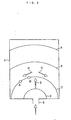
- Fig.2 illustrates a principle of this.
- numeral 4 designates a molding used for injection molding on a side of which gate 5 is provided.
- gate 5 has a much smaller cross section as compared with that of mold 4.
- molten resin material is injected from gate 5 and a molded product is taken out by opening the molding after being cooled and hardened.
- the molten resin material flowing from gate 5 has a velocity vector (three- dimension) having not only a straight- ahead component S but also components P and R vertical thereto. It is known that bonding chains of resin material are orientated approximately to a direction of velocity vector. Now paying attention to points A and B distant to some extent from each other on equiphase 7, bonding chains of resin material in the vicinity of point A are orientated roughly to a direction connecting an exit of gate 5 and point A and bonding chains of resin material in the vicinity of point B are orientated roughly to a direction connecting an exit of gate 5 and point B.
- the bonding chains are expected to form units (clusters) each of which consist of bonding chains moving cooperatively to some extent.
- the units are supposed to be about several ten Angstrom at most in size. Therefore, viewing in a much greater scale such as several hundred nm to several ten micron or more, the material flows and moves with velocity vectors (three- dimension) different from each other overall within the molding.
- flowing velocity has a gradient around a fine particle, in particular, at both particle ends of a long axis direction an external force is generated depending on the long axis direction, with the result that a moment is generated.
- this moment acts as to orientate the fine particle so that external forces acting on the particle both ends of the long axis direction have approximately equal components perpendicular to the long axis direction (Moment is eliminated under such an orientation ). According to this, it is supposed that the fine particles tend t to be orientated so that their long axes are directed roughly in parallel with equiphases 6 to 9.
- the present invention utilizes " inorganic fine particles having birefringence", which functions as to cancel or reduce birefringence with which a transparent resin matrix provided. Now described is birefringence of inorganic fine particles by referring to actual examples.
- crystals can be classified according to symmetric property of unit lattice composing them into crystal systems, such as tetragonal system, orthorhombic system.
- crystal systems such as tetragonal system, orthorhombic system.
- An inorganic fine particle is composed of some unit number of inorganic crystals gathered together. It should be noted that what form of outward figure is provided when actually gathered crystals compose a fine particle is not determined uniquely depending on crystal system.
- calcium carbonate can provide three crystal systems, calcite, paterite and aragonite. It is known that, in these, calcite is usually obtained under usual temperature and usual pressure and aragonite is obtained preferentially if crystals are grown under existence of a certain impurity (or catalyst).
- Aragonite have a crystal mannerism providing a rod- like form, as shown in a microscopic picture of Fig.3 that shows rod-like fine particles. This form is called also " needle- like " or " whisker- like " .
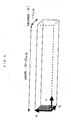
- Fig.4 is a schematic view of a rod-like fine particle of ones shown in Fig.3 .
- Particle size ranges, for example, from 10 ⁇ m to 30 ⁇ m in length and from 0.1 ⁇ m to 2 ⁇ m in thickness.
- Long axis direction of rod generally accords with c-axis of the crystal system. Both a-axis and b-axis give short axis directions.
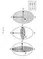
- Aragonite made of birefringent crystals, has birefringence which can be expressed by an index ellipsoid as shown in Figs.5(a), 5(b) and 5(c) .
- birefringence means anisotropy in refractive index which is illustrated by the index ellipsoid three-dimensionally.
- arrows (coordinate axes) designated by symbols n a , n b and n c correspond to a-axis, b- axis and c- axis of the crystal, respectively.
- Respective refractive index components for the respectively corresponding axis are expressed by respective distances between the origin and points (three points in total) at which the index ellipsoid (three-dimensional) and the respectively corresponding coordinate axes intersect.
- n a , n b and n c are also employed as symbols expressing their values.
- Fig.5(a) illustrates a case where light propagates from the left side to the right side in the illustration, namely, to a +- direction along n c axis (corresponding to c- axis direction), and effective refractive index for the light is expressed by a cross section (shaded; called ellipse ab hereafter) which cuts the ellipse with a plane that passes the center of the ellipse (i.e. the origin at which n a , n b and n c intersect) and extends perpendicularly to the light propagating direction.
- an electric field vibration component is parallel with a plane represented by ellipse bc.
- linearly polarized light propagates, there are (21) polarized light having an electric field vibrating in n b direction, (22) polarized light having an electric field vibrating in n c direction and (23) polarized light having an electric field vibrating in a direction between n b direction and n c direction, wherein (23) can be regarded as superposition of (21) and (22).
- So- called natural light contains (21), (22) and (23) together.
- an electric field vibration component is parallel with a plane represented by ellipse ca.
- 31) polarized light having an electric field vibrating in n c direction 32) polarized light having an electric field vibrating in n a direction
- (33) polarized light having an electric field vibrating in a direction between n c direction and n a direction 33) can be regarded as superposition of (31) and (32).
- So-called natural light contains (21), (22) and (23) together.
- Aragonite birefringence is outlined as above, giving a ⁇ n value of - 0.147 (negative value).
- combination is chosen so that ⁇ n of resin and that of inorganic fine particles have the same sign.
- an orientation direction of bonding chains of the resin material and that of inorganic fine particles represented by long axis direction are fixed in a state in which both directions are approximately perpendicular to each other.
- a molten resin material in which inorganic fine particles are dispersed is injected into a flowing space having a relatively large cross section through an opening having a relatively small cross section, then being caked.
- a material having non-birefringence is obtained by this method.
- Embodiments 1 to 4 are described as follows.
- Kneading was applied to needle-like crystals of basic magnesium sulfate MgSO 4 ⁇ 5Mg(OH) 2 ⁇ 3H 2 O (By UBE MATERIALS Ltd.; MOS ⁇ HIGE(Registered Trade Mark)) ranging 7 ⁇ m to 10 ⁇ m and transparent rein ARTON (Registered Trade Mark; JSR Ltd.) by means of a double-axle extruder to obtain pellets.
- Density of the added basic magnesium needle- like crystals was 0.5 parts by weight to 100 parts of ARTON.
- Injection molding was applied to the pellets by means of an injection molding machine (NISSEI JUSHI KOGYO Ltd.; Type HM- 7) to prepare a flat plate-like (35 mm ⁇ 35 mm ⁇ 2 mm) molding as shown in Fig.6 .
- the above molten resin containing the above inorganic fine particles dispersed therein was injected (poured) into a mold 4 having a shape like that shown in Fig.6 through a gate, then a plate-like sample being taken out by mold- opening after being cooled and hardened.
- Injection molding condition was such that nozzle temperature was 280 °C, cylinder temperature 280 °C, and mold temperature 90 °C.
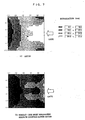
- Plane- distribution of degree and direction of retardation (birefringence value ⁇ n ⁇ light path length) of the prepared flat plate- shaped sample was measured by means of a birefringence measuring apparatus (By UNIOPT Ltd.; automatic birefringence measuring apparatus, ABR- 10A- EX).
- Results are shown in Figs.7(b) and 8(b) .
- the same measurement was applied to a reference sample and results were shown in Figs.7(a) and 8(a) .
- the reference sample was a resin plate having the same size and same shape as shown in Fig.6 which was prepared by applying injection molding to ARTON (Registered Trade Mark) containing no basic magnesium needle like crystal under the same condition.
- ARTON Registered Trade Mark
- retardation maps shown in Figs.7(a) and 7(b) illustrate retardation values of the light transmitting a plane surrounded by sides of 35 mm approximately perpendicularly for every 1 by 1 mm square segment.
- Edge portion ranging about 5 mm from the periphery was excluded from a meshed measurement area as shown in Fig.9 in order to prevent effects of refraction and diffraction of the light from bringing errors.
- a direction to which the smallest refractive index is provided for polarized light incident perpendicularly to each segment is defined as " advancing phase axis" and another direction vertical thereto which the largest refractive index is provided is defined as “ delaying phase axis " , and the phase difference between the polarized lights in the respective directions was calculated as retardation for each segment.
- Figs.8(a) and (b) are advancing phase axis maps, in which a linear line in each segment shows an advancing phase axis direction and a direction perpendicular thereto is a delaying phase axis direction. Degree of retardation is expressed stepwise by shading in each retardation map.
- a portion the nearest to the gate position of the employed mold generally corresponds to the middle of the right side end in each of retardation maps shown in Figs.7(a) and 7(b) .
- molten polymer flows into the mold from the right side, heading for the left side.
- the gate has a cross section which is, needless to say, much smaller than that of the mold at positions along the resin flow (approximately equal to cross section of the plate-like sample).
- advancing phase axes (directions giving a small refractive index) are directed, in the position corresponding to the gate, as to disposed along circumferences of concentric circles provisionally depicted from the position corresponding to the gate.
- Delaying phase axes (directions giving a large refractive index) are directed perpendicularly to advancing phase axes, being directed radially from the gate position.
- ARTON has a positive orientation birefringence (that is, refractive index for an orientation direction of polymer principal chains is larger than for a direction perpendicular thereto), principal chains of ARTON are orientated radially from the position corresponding to the gate.
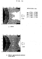
- Kneading was applied to needle- like crystals of Xonotlite 6CaO ⁇ 6SiO 2 ⁇ H 2 O (By UBE MATERIALS Ltd.; SONO ⁇ HIGE(Registered Trade Mark)) ranging 1 ⁇ m to 7 ⁇ m and transparent rein ARTON (Registered Trade Mark; JSR Ltd.) by means of a double- axle extruder to obtain pellets.
- Density of the added xonotlite needle-like crystals was 0.5 parts by weight to 100 parts of ARTON.
- Injection molding was applied to the pellets by means of an injection molding machine (NISSEI JUSHI KOGYO Ltd.; Type HM-7) to prepare a flat plate-like (35 mm ⁇ 35 mm ⁇ 2 mm) molding as shown in Fig.6 .
- NISSEI JUSHI KOGYO Ltd. Type HM-7
- the above molten resin containing the above inorganic fine particles dispersed therein was injected (poured) into a mold 4 having a shape like that shown in Fig.6 through a gate, then a plate-like sample being taken out by mold-opening after being cooled and hardened.
- Injection molding condition was such that nozzle temperature was 280 °C, cylinder temperature 280 °C, and mold temperature 90 °C.
- Plane- distribution of degree and direction of retardation (birefringence value ⁇ n ⁇ light path length) of the prepared flat plate- shaped sample was measured by means of a birefringence measuring apparatus (By UNIOPT Ltd.; automatic birefringence measuring apparatus, ABR- 10A-EX).
- Results are shown in Figs.10(b) and 11(b) .
- the same measurement was applied to a reference sample and results were shown in Figs.10(a) and 11(a) .
- the reference sample was a resin plate having the same size and same shape as shown in Fig.6 which was prepared by applying injection molding to ARTON (Registered Trade Mark) containing no inorganic fine particles under the same condition.
- ARTON Registered Trade Mark
- retardation maps shown in Figs.10(a) and 10(b) illustrate retardation values of the light transmitting a plane surrounded by sides of 35 mm approximately perpendicularly for every 1 by 1 mm square segment.
- Edge portion ranging about 5 mm from the periphery was excluded from a meshed measurement area as shown in Fig.9 in order to prevent effects of refraction and diffraction of the light from bringing errors, in the same manner as in Embodiment 1.
- a direction to which the smallest refractive index is provided for polarized light incident perpendicularly to each segment is defined as " advancing phase axis " and another direction vertical thereto which the largest refractive index is provided is defined as " delaying phase axis” , and the phase difference between the polarized lights in the respective directions was calculated as retardation for each segment.
- Figs.11(a) and (b) are advancing phase axis maps, in which a linear line in each segment shows an advancing phase axis direction and a direction perpendicular thereto is a delaying phase axis direction. Degree of retardation is expressed stepwise by shading in each retardation map.
- a portion the nearest to the gate position of the employed mold generally corresponds to the middle of the right side end in each of retardation maps shown in Figs.7(a) and 7(b) .
- molten polymer flows into the mold from the right side, heading for the left side.
- the gate has a cross section which is, needless to say, much smaller than that of the mold at positions along the resin flow (approximately equal to cross section of the plate-like sample).
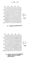
- Kneading was applied to needle-like crystals of aragonite type calcium carbonate CaCO 3 ranging 1 ⁇ m to 5 ⁇ m and transparent methyl methacrylate resin (By MITSUBISHI RAYON Co., Ltd. ACRYPET (Registered Trade Mark) by means of a double-axle extruder to obtain pellets. Density of the added calcium carbonate needle-like crystals was 0.02 parts by weight to 100 parts of methyl methacrylate.
- Injection molding was applied to the pellets by means of an injection molding machine (NISSEI JUSHI KOGYO Ltd.; Type HM-7) to prepare a flat plate-like (35 mm X 35 mm X 2 mm) molding as shown in Fig.6 .
- the above molten resin containing the above inorganic fine particles dispersed therein was injected (poured) into a mold 4 having a shape like that shown in Fig.6 through a gate, then a plate-like sample being taken out by mold- opening after being cooled and hardened.
- Injection molding condition was such that nozzle temperature was 250 °C, cylinder temperature 250 °C, and mold temperature 80 °C.
- Plane- distribution of degree and direction of retardation (birefringence value ⁇ n ⁇ light path length) of the prepared flat plate- shaped sample was measured by means of a birefringence measuring apparatus (By UNIOPT Ltd.; automatic birefringence measuring apparatus, ABR- 10A-EX).
- Results are shown in Figs.12(b) and 13(b) .
- the same measurement was applied to a reference sample and results were shown in Figs.12(a) and 13(a) .
- the reference sample was a resin plate having the same size and same shape as shown in Fig.6 which was prepared by applying injection molding to polymethyl methacrylate containing no inorganic fine particles under the same condition.
- retardation maps shown in Figs.12(a) and 13(b) illustrate retardation values of the light transmitting a plane surrounded by sides of 35 mm approximately perpendicularly for every 1 by 1 mm square segment.
- Edge portion ranging about 5 mm from the periphery was excluded from a meshed measurement area as shown in Fig.9 in order to prevent effects of refraction and diffraction of the light from bringing errors in the same manner as in the case of Embodiment 1.
- a direction to which the smallest refractive index is provided for polarized light incident perpendicularly to each segment is defined as "advancing phase axis" and another direction vertical thereto which the largest refractive index is provided is defined as “delaying phase axis” , and the phase difference between the polarized lights in the respective directions was calculated as retardation for each segment.
- Figs.13(a) and (b) are advancing phase axis maps, in which a linear line in each segment shows an advancing phase axis direction and a direction perpendicular thereto is a delaying phase axis direction. Degree of retardation is expressed stepwise by shading in each retardation map.
- a portion the nearest to the gate position of the employed mold generally corresponds to the middle of the right side end in each of retardation maps shown in Figs.7(a) and 7(b) .
- molten polymer also flows into the mold from the right side, heading for the left side.
- the gate has a cross section which is, needless to say, much smaller than that of the mold at positions along the resin flow (approximately equal to cross section of the plate-like sample).
- advancing phase axes are directed radially from the position corresponding to the gate in the vicinity thereof.
- Delaying phase axes are directed perpendicularly to advancing phase axes, being directed along circumferences of concentric circles provisionally depicted from the position corresponding to the gate.
- polymethyl methacrylate has a negative orientation birefringence (that is, refractive index for an orientation direction of polymer principal chains is smaller than for a direction perpendicular thereto)
- principal chains of polymethyl methacrylate are orientated radially from the position corresponding to the gate.
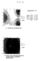
- Kneading was applied to needle-like crystals of strontium carbonate SrCO 3 ranging 0.6 ⁇ m to 1 ⁇ m and transparent methyl methacrylate resin (By MITSUBISHI RAYON Co., Ltd. ACRYPET (Registered Trade Mark) by means of a double-axle extruder to obtain pellets. Density of the added strontium carbonate needle-like crystals was 0.02 parts by weight to 100 parts of methyl methacrylate.
- Injection molding was applied to the pellets by means of an injection molding machine (NISSEI JUSHI KOGYO Ltd.; Type HM-7) to prepare a flat plate-like (35 mm ⁇ 35 mm ⁇ 2 mm) molding as shown in Fig.6 .
- NISSEI JUSHI KOGYO Ltd. Type HM-7
- the above molten resin containing the above inorganic fine particles dispersed therein was injected (poured) into a mold 4 having a shape like that shown in Fig.6 through a gate, then a plate-like sample being taken out by mold-opening after being cooled and hardened.
- Injection molding condition was such that nozzle temperature was 250 °C, cylinder temperature 250 °C, and mold temperature 80 °C.
- Plane- distribution of degree and direction of retardation (birefringence value ⁇ n ⁇ light path length) of the prepared flat plate- shaped sample was measured by means of a birefringence measuring apparatus (By UNIOPT Ltd.; automatic birefringence measuring apparatus, ABR- 10A- EX).
- Results are shown in Figs.14(b) and 15(b) .
- the same measurement was applied to a reference sample and results were shown in Figs.14(a) and 15(a) .
- the reference sample was a resin plate having the same size and same shape as shown in Fig.6 which was prepared by applying injection molding to polymethyl methacrylate containing no inorganic fine particles under the same condition.
- retardation maps shown in Figs.14(a) and 14(b) illustrate retardation values of the light transmitting a plane surrounded by sides of 35 mm approximately perpendicularly for every 1 by 1 mm square segment.
- Edge portion ranging about 5 mm from the periphery was excluded from a meshed measurement area as shown in Fig.9 in order to prevent effects of refraction and diffraction of the light from bringing errors, in the same manner as in Embodiment 1 and others.
- a direction to which the smallest refractive index is provided for polarized light incident perpendicularly to each segment is defined as "advancing phase axis" and another direction vertical thereto which the largest refractive index is provided is defined as “ delaying phase axis” , and the phase difference between the polarized lights in the respective directions was calculated as retardation for each segment.
- Figs.15(a) and (b) are advancing phase axis maps, in which a linear line in each segment shows an advancing phase axis direction and a direction perpendicular thereto is a delaying phase axis direction. Degree of retardation is expressed stepwise by shading in each retardation map.
- molten polymer also flows into the mold from the right side, heading for the left side.
- the gate has a cross section which is, needless to say, much smaller than that of the mold at positions along the resin flow (approximately equal to cross section of the plate- like sample).
- Examples of typical optical polymers commercially available are as follows. Moreover, examples of needle-like crystals positive or negative sign of which is known already.
- needle-like crystals such as potassium titanate or magnesium carbonate, although positive/negative is not distinguished for the time being, are expected as applicable ones.
- Non- birefringent resin materials obtained by the present invention may be applied to optical elements for optional uses due to non-birefringent characteristics, marked high workability of resin material, mass- productivity and other factors. On eof them is application to LCD element.
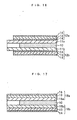
- Fig.16 is a cross section view of an example of LCD element including a liquid crystal layer, polarization plate and a resin sheet, interposed between them, to which a non-birefringent resin material obtained by the present invention is applied.
- a liquid crystal layer is designated by numeral 10, being sealed between substrate 11a and 11b.
- a pair of polarizing plate units 12a and 12b are disposed on both sides of substrates 11a and 11b.
- Each of polarizing plate units 12a and 12b is structured so that a polarizing plate 13 is sandwiched by resin sheets 14.
- Resin sheets 14 may be made of a material such as one obtained in Embodiment 1, 2 or 3. Resin sheets 14 not only protect polarizing plate 13 but also enables light transmission to avoid beam separation from being caused by birefringence.
- Fig.17 is a cross section view of another example of LCD element including a liquid crystal layer, polarization plate and a resin sheet, interposed between them, to which a non-birefringent resin material obtained by the present invention is applied.
- a liquid crystal layer is designated by numeral 10, being sealed between substrates 15a and 15b.
- a pair of polarizing plate units 16a and 16b are disposed on both sides of substrates 15a and 15b.
- Each of polarizing plate units 16a and 16b is structured so that a polarizing plate 13 is covered by resin sheet 14 from the outside.
- Resin sheets 14 may be made of a material such as one obtained in Embodiment 1, 2 or 3. Resin sheets 14 not only protect polarizing plate 13 but also enables light transmission to avoid beam separation from being caused by birefringence.
- the present invention can provides a non-birefringent optical resin material composed of a resin material and a inorganic fine particle material which have the same sign of birefringence and a simple method of producing it.
- the provided material may be applied to optical elements for optional uses due to non-birefringent characteristics, marked high workability of resin material, mass- productivity and other factors.
Landscapes
- Engineering & Computer Science (AREA)
- Manufacturing & Machinery (AREA)
- Mechanical Engineering (AREA)
- Chemical & Material Sciences (AREA)
- Dispersion Chemistry (AREA)
- Physics & Mathematics (AREA)
- General Physics & Mathematics (AREA)
- Optics & Photonics (AREA)
- Polarising Elements (AREA)
- Compositions Of Macromolecular Compounds (AREA)
- Manufacture Of Macromolecular Shaped Articles (AREA)
- Casting Or Compression Moulding Of Plastics Or The Like (AREA)
- Processing And Handling Of Plastics And Other Materials For Molding In General (AREA)
- Disintegrating Or Milling (AREA)
- Moulds For Moulding Plastics Or The Like (AREA)
Claims (4)
- Matériau de résine optique non biréfringent contenant une résine de polymère transparente durcie après fluage et un grand nombre de fines particules inorganiques dispersées dans ladite résine de polymère ;caractérisé en ce que chacune desdites fines particules a une forme de type tige ayant un grand axe, lesdites fines particules ayant une orientation-biréfringence par laquelle celle de la résine de polymère est renforcée si les directions de grand axe des fines particules inorganiques sont parallèles à une direction d'orientation de chaînes de liaison de ladite résine de polymère et est annulée si les directions de grand axe des fines particules inorganiques sont perpendiculaires à la direction d'orientation de chaînes de liaison de ladite résine de polymère, etlesdites chaînes de liaison de ladite résine de polymère sont orientées dans une direction d'orientation correspondant à une force externe appliquée pendant ledit fluage, etlesdites fines particules sont orientées approximativement perpendiculairement à ladite direction d'orientation desdites chaînes de liaison, donnant ainsi une non-biréfringence audit matériau de résine optique.
- Matériau de résine optique non biréfringent selon la revendication 1, dans lequel ledit fluage est induit lorsqu'un matériau contenant ledit matériau de résine dans un état fondu et ledit grand nombre de fines particules organiques est injecté dans un espace de fluage ayant une section relativement grande à travers l'ouverture (5) ayant une section relativement petite.
- Procédé de production d'un matériau de résine optique non biréfringent contenant une résine polymère transparente durcie après fluage et un grand nombre de fines particules inorganiques dispersées dans ladite résine de polymère ;caractérisé en ce que chacune desdites fines particules a une forme de type tige ayant un grand axe, lesdites fines particules ayant une orientation-biréfringence par laquelle celle de la résine de polymère est renforcée si les directions de grand axe des fines particules inorganiques sont parallèles à une direction d'orientation de chaînes de liaison de ladite résine de polymère et est annulée si les directions de grand axe des fines particules inorganiques sont perpendiculaires à la direction d'orientation de chaînes de liaison de ladite résine de polymère, le procédé comprenant les étapes consistant à :amener un grand nombre de fines particules à coexister avec et à être dispersées dans une résine de polymère transparente dans un état de fluage, orientant ainsi lesdites chaînes de liaison de ladite résine de polymère dans une direction correspondant à celle dudit fluage et orientant lesdites fines particules inorganiques de façon à ce qu'elles soient approximativement perpendiculaires à une direction dudit fluage, etfixer une relation entre l'orientation des chaînes de liaison de ladite résine de polymère et celle desdites fines particules inorganiques à l'aide d'un processus de durcissement.
- Procédé de production d'un matériau de résine optique non biréfringent selon la revendication 3, dans lequel ledit état de fluage est induit dans un espace de fluage lorsqu'un matériau contenant ledit matériau de résine dans un état fondu et ledit grand nombre de fines particules inorganiques est injecté dans ledit espace de fluage ayant une section relativement grande à travers l'ouverture (5) ayant une section relativement petite.
Applications Claiming Priority (3)
| Application Number | Priority Date | Filing Date | Title |
|---|---|---|---|
| JP2002067457 | 2002-03-12 | ||
| JP2002067457 | 2002-03-12 | ||
| PCT/JP2003/002790 WO2003076982A1 (fr) | 2002-03-12 | 2003-03-10 | Materiau de resine optique non birefringent et son procede de production |
Publications (3)
| Publication Number | Publication Date |
|---|---|
| EP1486800A1 EP1486800A1 (fr) | 2004-12-15 |
| EP1486800A4 EP1486800A4 (fr) | 2007-08-01 |
| EP1486800B1 true EP1486800B1 (fr) | 2009-06-03 |
Family
ID=27800284
Family Applications (1)
| Application Number | Title | Priority Date | Filing Date |
|---|---|---|---|
| EP03744038A Expired - Lifetime EP1486800B1 (fr) | 2002-03-12 | 2003-03-10 | Materiau de resine optique non birefringent et son procede de production |
Country Status (9)
| Country | Link |
|---|---|
| US (1) | US7485676B2 (fr) |
| EP (1) | EP1486800B1 (fr) |
| JP (1) | JP4336586B2 (fr) |
| KR (1) | KR100966778B1 (fr) |
| CN (1) | CN100445771C (fr) |
| AT (1) | ATE433127T1 (fr) |
| DE (1) | DE60327844D1 (fr) |
| TW (1) | TWI275471B (fr) |
| WO (1) | WO2003076982A1 (fr) |
Families Citing this family (14)
| Publication number | Priority date | Publication date | Assignee | Title |
|---|---|---|---|---|
| JP4624845B2 (ja) * | 2005-04-26 | 2011-02-02 | 康博 小池 | 非複屈折性光学樹脂材料及び光学部材 |
| US20100087578A1 (en) * | 2005-06-24 | 2010-04-08 | Fujifilm Corporation | Optical resin composition and method for producing the same |
| JP2010055115A (ja) * | 2009-12-08 | 2010-03-11 | Tosoh Corp | 位相差フィルム |
| US8936773B2 (en) * | 2011-04-28 | 2015-01-20 | Calera Corporation | Methods and compositions using calcium carbonate and stabilizer |
| CN104334635B (zh) | 2012-06-26 | 2017-11-10 | 株式会社钟化 | 非双折射性树脂材料及膜 |
| WO2014162370A1 (fr) | 2013-04-05 | 2014-10-09 | 株式会社カネカ | Matériau de résine optique, et film optique |
| CN105102534B (zh) | 2013-04-05 | 2019-08-23 | 株式会社钟化 | 树脂组合物及其膜 |
| EP3072926A4 (fr) | 2013-11-22 | 2017-09-27 | Kaneka Corporation | Matériau de résine et son film |
| WO2015079693A1 (fr) | 2013-11-29 | 2015-06-04 | 株式会社カネカ | Composition et film de résine optique |
| WO2015079694A1 (fr) | 2013-11-29 | 2015-06-04 | 株式会社カネカ | Composition et film de résine optique |
| CN111607181B (zh) | 2013-12-25 | 2023-05-05 | 株式会社钟化 | 光学用树脂组合物及成形体 |
| CN105829923B (zh) | 2013-12-27 | 2020-01-21 | 株式会社钟化 | 光学用热塑性树脂及成形体 |
| JP7145150B2 (ja) | 2017-05-16 | 2022-09-30 | 株式会社カネカ | フィルム製造用ドープ、及びフィルムの製造方法 |
| CN109401409A (zh) * | 2018-11-04 | 2019-03-01 | 广西南宁维防腐科技有限公司 | 一种建筑外墙隔热涂料及其制备方法 |
Family Cites Families (15)
| Publication number | Priority date | Publication date | Assignee | Title |
|---|---|---|---|---|
| US3265777A (en) * | 1963-07-29 | 1966-08-09 | Alvin M Marks | Light polarizing film and fibre forming method |
| US4373065A (en) * | 1981-02-17 | 1983-02-08 | Xerox Corporation | Optically isotropic devices |
| JPS6119656A (ja) | 1984-07-07 | 1986-01-28 | Mitsubishi Chem Ind Ltd | 光学機器用成形材料 |
| JPS61108617A (ja) | 1984-11-02 | 1986-05-27 | Sumitomo Chem Co Ltd | 光学樹脂材料 |
| JPH06101140B2 (ja) | 1985-12-06 | 1994-12-12 | 住友化学工業株式会社 | 光学素子 |
| JP2684112B2 (ja) | 1989-06-29 | 1997-12-03 | 丸尾カルシウム株式会社 | 針状形状をしたアラゴナイト結晶形炭酸カルシウムの製造方法 |
| WO1994015005A1 (fr) * | 1992-12-18 | 1994-07-07 | Hoechst Celanese Corporation | Articles formes ayant un indice de refraction variant graduellement |
| JP3696649B2 (ja) | 1994-08-18 | 2005-09-21 | 康博 小池 | 非複屈折性の光学樹脂材料及びその製造方法並びに光学樹脂材料を用いた液晶素子用の部材 |
| JP4870248B2 (ja) * | 1996-02-29 | 2012-02-08 | スリーエム カンパニー | 輝度増強フィルム |
| JP3486325B2 (ja) * | 1997-06-26 | 2004-01-13 | 日本電信電話株式会社 | ポリアミド酸溶液、ポリイミドフィルムおよびポリイミドフィルムの特性制御方法 |
| JPH11174209A (ja) | 1997-10-23 | 1999-07-02 | Eastman Kodak Co | 射出成形によって光学レンズを製造するためのガラス充填透明プラスチック |
| JPH11293116A (ja) | 1998-04-06 | 1999-10-26 | Yasuhiro Koike | 非複屈折性の光学樹脂材料 |
| JP4105331B2 (ja) | 1999-04-30 | 2008-06-25 | Jsr株式会社 | 低複屈折性光学樹脂材料およびその製造方法並びにその応用 |
| JP3648201B2 (ja) * | 1999-10-05 | 2005-05-18 | 康博 小池 | 非複屈折性の光学樹脂材料 |
| JP2001208901A (ja) | 2000-01-26 | 2001-08-03 | Jsr Corp | 低複屈折性光学樹脂材料およびその製造方法並びにその応用 |
-
2003
- 2003-03-10 DE DE60327844T patent/DE60327844D1/de not_active Expired - Lifetime
- 2003-03-10 WO PCT/JP2003/002790 patent/WO2003076982A1/fr not_active Ceased
- 2003-03-10 AT AT03744038T patent/ATE433127T1/de not_active IP Right Cessation
- 2003-03-10 CN CNB038057603A patent/CN100445771C/zh not_active Expired - Lifetime
- 2003-03-10 US US10/506,978 patent/US7485676B2/en not_active Expired - Lifetime
- 2003-03-10 KR KR1020047013139A patent/KR100966778B1/ko not_active Expired - Lifetime
- 2003-03-10 EP EP03744038A patent/EP1486800B1/fr not_active Expired - Lifetime
- 2003-03-10 TW TW092105068A patent/TWI275471B/zh not_active IP Right Cessation
- 2003-03-10 JP JP2003575151A patent/JP4336586B2/ja not_active Expired - Lifetime
Also Published As
| Publication number | Publication date |
|---|---|
| KR100966778B1 (ko) | 2010-06-29 |
| ATE433127T1 (de) | 2009-06-15 |
| JPWO2003076982A1 (ja) | 2005-07-07 |
| US7485676B2 (en) | 2009-02-03 |
| EP1486800A1 (fr) | 2004-12-15 |
| KR20040095229A (ko) | 2004-11-12 |
| WO2003076982A1 (fr) | 2003-09-18 |
| EP1486800A4 (fr) | 2007-08-01 |
| DE60327844D1 (de) | 2009-07-16 |
| TW200306328A (en) | 2003-11-16 |
| CN100445771C (zh) | 2008-12-24 |
| CN1643404A (zh) | 2005-07-20 |
| JP4336586B2 (ja) | 2009-09-30 |
| TWI275471B (en) | 2007-03-11 |
| US20050119389A1 (en) | 2005-06-02 |
Similar Documents
| Publication | Publication Date | Title |
|---|---|---|
| US7485676B2 (en) | Non-birefringent optical resin material and its producing method | |
| KR100195592B1 (ko) | 다배향성 광 제어 필름 | |
| EP2103968B1 (fr) | Elément polarisant et dispositif d'affichage à cristaux liquides | |
| KR100626573B1 (ko) | 비복굴절성 광학수지 재료 | |
| KR960002304B1 (ko) | 광제어판 및 그 제조방법 | |
| EP0740168B1 (fr) | Resine optique non-birefringente, son procede de fabrication, et article en elements de cristaux liquides utilisant une telle resine | |
| Ruhl et al. | Colloidal crystals in latex films: Rubbery opals | |
| JPWO2001025364A1 (ja) | 非複屈折性の光学樹脂材料 | |
| KR101555713B1 (ko) | 위상차판의 제조 방법 | |
| KR20120030536A (ko) | 광 제어 필름 | |
| KR20140006814A (ko) | 위상차 필름 적층체 및 위상차 필름 적층체의 제조방법 | |
| US6462794B1 (en) | Image forming unit, enlarging unit, optical parts, and image display apparatus having these components | |
| JP2004109355A (ja) | 光学材料の製造方法、光学材料並びに光学素子 | |
| JP2021162623A (ja) | 反射偏光板 | |
| KR20010024649A (ko) | 직선 편광을 출사하는 광 전도체를 포함하는 광원 장치의액정 표시소자에 대한 적용 | |
| JP3545803B2 (ja) | 偏光化機能付面光源装置 | |
| JPH11293116A (ja) | 非複屈折性の光学樹脂材料 | |
| JP2004226503A (ja) | 偏光度低下型光学素子及びそれを用いた面光源装置並びに液晶ディスプレイ | |
| Obuchi et al. | High performance optical materials cyclo olefin polymer ZEONEX | |
| Kurashima et al. | 60.2: A polarized laser backlight using a polymer free of orientational and photoelastic birefringence | |
| JPH0249304A (ja) | 光線調整フィルムもしくはシートの製造方法 | |
| JPH07241917A (ja) | 視野選択性プロピレン系樹脂フィルム及びその製造方法 | |
| JP2001092367A (ja) | 反射型表示装置 | |
| Milanovic | Solid matrix Christiansen filters | |
| JP2013076874A (ja) | 偏光分離フィルム、面光源装置および液晶表示装置 |
Legal Events
| Date | Code | Title | Description |
|---|---|---|---|
| PUAI | Public reference made under article 153(3) epc to a published international application that has entered the european phase |
Free format text: ORIGINAL CODE: 0009012 |
|
| 17P | Request for examination filed |
Effective date: 20041006 |
|
| AK | Designated contracting states |
Kind code of ref document: A1 Designated state(s): AT BE BG CH CY CZ DE DK EE ES FI FR GB GR HU IE IT LI LU MC NL PT RO SE SI SK TR |
|
| A4 | Supplementary search report drawn up and despatched |
Effective date: 20070629 |
|
| 17Q | First examination report despatched |
Effective date: 20070905 |
|
| GRAP | Despatch of communication of intention to grant a patent |
Free format text: ORIGINAL CODE: EPIDOSNIGR1 |
|
| GRAS | Grant fee paid |
Free format text: ORIGINAL CODE: EPIDOSNIGR3 |
|
| GRAA | (expected) grant |
Free format text: ORIGINAL CODE: 0009210 |
|
| AK | Designated contracting states |
Kind code of ref document: B1 Designated state(s): AT BE BG CH CY CZ DE DK EE ES FI FR GB GR HU IE IT LI LU MC NL PT RO SE SI SK TR |
|
| REG | Reference to a national code |
Ref country code: GB Ref legal event code: FG4D |
|
| REG | Reference to a national code |
Ref country code: CH Ref legal event code: EP |
|
| REG | Reference to a national code |
Ref country code: IE Ref legal event code: FG4D |
|
| REF | Corresponds to: |
Ref document number: 60327844 Country of ref document: DE Date of ref document: 20090716 Kind code of ref document: P |
|
| PG25 | Lapsed in a contracting state [announced via postgrant information from national office to epo] |
Ref country code: FI Free format text: LAPSE BECAUSE OF FAILURE TO SUBMIT A TRANSLATION OF THE DESCRIPTION OR TO PAY THE FEE WITHIN THE PRESCRIBED TIME-LIMIT Effective date: 20090603 Ref country code: AT Free format text: LAPSE BECAUSE OF FAILURE TO SUBMIT A TRANSLATION OF THE DESCRIPTION OR TO PAY THE FEE WITHIN THE PRESCRIBED TIME-LIMIT Effective date: 20090603 |
|
| NLV1 | Nl: lapsed or annulled due to failure to fulfill the requirements of art. 29p and 29m of the patents act | ||
| PG25 | Lapsed in a contracting state [announced via postgrant information from national office to epo] |
Ref country code: NL Free format text: LAPSE BECAUSE OF FAILURE TO SUBMIT A TRANSLATION OF THE DESCRIPTION OR TO PAY THE FEE WITHIN THE PRESCRIBED TIME-LIMIT Effective date: 20090603 Ref country code: SE Free format text: LAPSE BECAUSE OF FAILURE TO SUBMIT A TRANSLATION OF THE DESCRIPTION OR TO PAY THE FEE WITHIN THE PRESCRIBED TIME-LIMIT Effective date: 20090903 Ref country code: SI Free format text: LAPSE BECAUSE OF FAILURE TO SUBMIT A TRANSLATION OF THE DESCRIPTION OR TO PAY THE FEE WITHIN THE PRESCRIBED TIME-LIMIT Effective date: 20090603 |
|
| PG25 | Lapsed in a contracting state [announced via postgrant information from national office to epo] |
Ref country code: RO Free format text: LAPSE BECAUSE OF FAILURE TO SUBMIT A TRANSLATION OF THE DESCRIPTION OR TO PAY THE FEE WITHIN THE PRESCRIBED TIME-LIMIT Effective date: 20090603 Ref country code: CZ Free format text: LAPSE BECAUSE OF FAILURE TO SUBMIT A TRANSLATION OF THE DESCRIPTION OR TO PAY THE FEE WITHIN THE PRESCRIBED TIME-LIMIT Effective date: 20090603 Ref country code: ES Free format text: LAPSE BECAUSE OF FAILURE TO SUBMIT A TRANSLATION OF THE DESCRIPTION OR TO PAY THE FEE WITHIN THE PRESCRIBED TIME-LIMIT Effective date: 20090914 Ref country code: EE Free format text: LAPSE BECAUSE OF FAILURE TO SUBMIT A TRANSLATION OF THE DESCRIPTION OR TO PAY THE FEE WITHIN THE PRESCRIBED TIME-LIMIT Effective date: 20090603 |
|
| PG25 | Lapsed in a contracting state [announced via postgrant information from national office to epo] |
Ref country code: SK Free format text: LAPSE BECAUSE OF FAILURE TO SUBMIT A TRANSLATION OF THE DESCRIPTION OR TO PAY THE FEE WITHIN THE PRESCRIBED TIME-LIMIT Effective date: 20090603 Ref country code: BE Free format text: LAPSE BECAUSE OF FAILURE TO SUBMIT A TRANSLATION OF THE DESCRIPTION OR TO PAY THE FEE WITHIN THE PRESCRIBED TIME-LIMIT Effective date: 20090603 |
|
| PG25 | Lapsed in a contracting state [announced via postgrant information from national office to epo] |
Ref country code: BG Free format text: LAPSE BECAUSE OF FAILURE TO SUBMIT A TRANSLATION OF THE DESCRIPTION OR TO PAY THE FEE WITHIN THE PRESCRIBED TIME-LIMIT Effective date: 20090903 Ref country code: PT Free format text: LAPSE BECAUSE OF FAILURE TO SUBMIT A TRANSLATION OF THE DESCRIPTION OR TO PAY THE FEE WITHIN THE PRESCRIBED TIME-LIMIT Effective date: 20091003 |
|
| PLBE | No opposition filed within time limit |
Free format text: ORIGINAL CODE: 0009261 |
|
| STAA | Information on the status of an ep patent application or granted ep patent |
Free format text: STATUS: NO OPPOSITION FILED WITHIN TIME LIMIT |
|
| PG25 | Lapsed in a contracting state [announced via postgrant information from national office to epo] |
Ref country code: DK Free format text: LAPSE BECAUSE OF FAILURE TO SUBMIT A TRANSLATION OF THE DESCRIPTION OR TO PAY THE FEE WITHIN THE PRESCRIBED TIME-LIMIT Effective date: 20090603 |
|
| 26N | No opposition filed |
Effective date: 20100304 |
|
| PG25 | Lapsed in a contracting state [announced via postgrant information from national office to epo] |
Ref country code: MC Free format text: LAPSE BECAUSE OF NON-PAYMENT OF DUE FEES Effective date: 20100331 Ref country code: GR Free format text: LAPSE BECAUSE OF FAILURE TO SUBMIT A TRANSLATION OF THE DESCRIPTION OR TO PAY THE FEE WITHIN THE PRESCRIBED TIME-LIMIT Effective date: 20090904 |
|
| REG | Reference to a national code |
Ref country code: CH Ref legal event code: PL |
|
| PG25 | Lapsed in a contracting state [announced via postgrant information from national office to epo] |
Ref country code: IE Free format text: LAPSE BECAUSE OF NON-PAYMENT OF DUE FEES Effective date: 20100310 |
|
| PG25 | Lapsed in a contracting state [announced via postgrant information from national office to epo] |
Ref country code: CH Free format text: LAPSE BECAUSE OF NON-PAYMENT OF DUE FEES Effective date: 20100331 Ref country code: LI Free format text: LAPSE BECAUSE OF NON-PAYMENT OF DUE FEES Effective date: 20100331 |
|
| PG25 | Lapsed in a contracting state [announced via postgrant information from national office to epo] |
Ref country code: IT Free format text: LAPSE BECAUSE OF FAILURE TO SUBMIT A TRANSLATION OF THE DESCRIPTION OR TO PAY THE FEE WITHIN THE PRESCRIBED TIME-LIMIT Effective date: 20090603 |
|
| PG25 | Lapsed in a contracting state [announced via postgrant information from national office to epo] |
Ref country code: CY Free format text: LAPSE BECAUSE OF FAILURE TO SUBMIT A TRANSLATION OF THE DESCRIPTION OR TO PAY THE FEE WITHIN THE PRESCRIBED TIME-LIMIT Effective date: 20090603 |
|
| PG25 | Lapsed in a contracting state [announced via postgrant information from national office to epo] |
Ref country code: LU Free format text: LAPSE BECAUSE OF NON-PAYMENT OF DUE FEES Effective date: 20100310 Ref country code: HU Free format text: LAPSE BECAUSE OF FAILURE TO SUBMIT A TRANSLATION OF THE DESCRIPTION OR TO PAY THE FEE WITHIN THE PRESCRIBED TIME-LIMIT Effective date: 20091204 |
|
| PG25 | Lapsed in a contracting state [announced via postgrant information from national office to epo] |
Ref country code: TR Free format text: LAPSE BECAUSE OF FAILURE TO SUBMIT A TRANSLATION OF THE DESCRIPTION OR TO PAY THE FEE WITHIN THE PRESCRIBED TIME-LIMIT Effective date: 20090603 |
|
| REG | Reference to a national code |
Ref country code: FR Ref legal event code: PLFP Year of fee payment: 14 |
|
| REG | Reference to a national code |
Ref country code: FR Ref legal event code: PLFP Year of fee payment: 15 |
|
| REG | Reference to a national code |
Ref country code: FR Ref legal event code: PLFP Year of fee payment: 16 |
|
| REG | Reference to a national code |
Ref country code: DE Ref legal event code: R082 Ref document number: 60327844 Country of ref document: DE Representative=s name: HL KEMPNER PATENTANWALT, RECHTSANWALT, SOLICIT, DE |
|
| PGFP | Annual fee paid to national office [announced via postgrant information from national office to epo] |
Ref country code: GB Payment date: 20220322 Year of fee payment: 20 Ref country code: DE Payment date: 20220322 Year of fee payment: 20 |
|
| PGFP | Annual fee paid to national office [announced via postgrant information from national office to epo] |
Ref country code: FR Payment date: 20220321 Year of fee payment: 20 |
|
| REG | Reference to a national code |
Ref country code: DE Ref legal event code: R071 Ref document number: 60327844 Country of ref document: DE |
|
| REG | Reference to a national code |
Ref country code: GB Ref legal event code: PE20 Expiry date: 20230309 |
|
| PG25 | Lapsed in a contracting state [announced via postgrant information from national office to epo] |
Ref country code: GB Free format text: LAPSE BECAUSE OF EXPIRATION OF PROTECTION Effective date: 20230309 |