EP1486813A1 - Microscope stéreoscopique à tube d'observation additionel - Google Patents
Microscope stéreoscopique à tube d'observation additionel Download PDFInfo
- Publication number
- EP1486813A1 EP1486813A1 EP04102515A EP04102515A EP1486813A1 EP 1486813 A1 EP1486813 A1 EP 1486813A1 EP 04102515 A EP04102515 A EP 04102515A EP 04102515 A EP04102515 A EP 04102515A EP 1486813 A1 EP1486813 A1 EP 1486813A1
- Authority
- EP
- European Patent Office
- Prior art keywords
- assistant
- beam path
- tube
- housing
- stereo
- Prior art date
- Legal status (The legal status is an assumption and is not a legal conclusion. Google has not performed a legal analysis and makes no representation as to the accuracy of the status listed.)
- Withdrawn
Links
- 238000000926 separation method Methods 0.000 claims description 28
- 230000003287 optical effect Effects 0.000 claims description 16
- 239000000243 solution Substances 0.000 description 11
- 230000000295 complement effect Effects 0.000 description 1
- 238000010276 construction Methods 0.000 description 1
- 230000001419 dependent effect Effects 0.000 description 1
- 238000011161 development Methods 0.000 description 1
- 230000018109 developmental process Effects 0.000 description 1
- 230000036512 infertility Effects 0.000 description 1
- 238000002347 injection Methods 0.000 description 1
- 239000007924 injection Substances 0.000 description 1
- 238000009434 installation Methods 0.000 description 1
- 230000000873 masking effect Effects 0.000 description 1
- 238000000034 method Methods 0.000 description 1
- 238000003032 molecular docking Methods 0.000 description 1
- 239000007787 solid Substances 0.000 description 1
- 230000001629 suppression Effects 0.000 description 1
Images




Classifications
-
- G—PHYSICS
- G02—OPTICS
- G02B—OPTICAL ELEMENTS, SYSTEMS OR APPARATUS
- G02B21/00—Microscopes
- G02B21/18—Arrangements with more than one light path, e.g. for comparing two specimens
- G02B21/20—Binocular arrangements
- G02B21/22—Stereoscopic arrangements
-
- G—PHYSICS
- G02—OPTICS
- G02B—OPTICAL ELEMENTS, SYSTEMS OR APPARATUS
- G02B21/00—Microscopes
- G02B21/18—Arrangements with more than one light path, e.g. for comparing two specimens
-
- G—PHYSICS
- G02—OPTICS
- G02B—OPTICAL ELEMENTS, SYSTEMS OR APPARATUS
- G02B21/00—Microscopes
- G02B21/24—Base structure
- G02B21/26—Stages; Adjusting means therefor
Definitions
- the invention relates to a stereo microscope with a monoscopic or conditionally stereoscopic observer tube (assistant tube).
- Stereomicroscopes with such tubes are well known and especially in ophthalmic and neurosurgical Operations now become essential.
- the assistant either on the left or right side of the microscope.
- suitable monoscopic or conditionally stereoscopic Assistant tubes is that from either the left or right Main beam path of the stereomicroscope using an optical Beam splitter an assistant beam path is hidden on the side.
- the desire to select the assistant either left or right can only be placed under certain solutions with the existing solutions restrictive requirements are met.
- stereomicroscope is intended for this, only on one side an assistant beam path from a main beam path to hide, a corresponding stereo microscope would have to be used left or right assistant tube. Latter Choice between two different stereo microscopes is usually not given, so in this case the Not at all or only with an expensive second solution be met.
- the stereomicroscope has a Assistant tube is equipped, so the desire could Placing assistants either on the left or right, of course optimal be met. Equipped with a stereo microscope two fixed assistant tubes instead of a swiveling one would be out Weight and cost reasons also not advantageous.
- Another disadvantage is that data in one of the two main stereo beam paths are reflected, also accordingly in one of the both assistant beam paths must be reflected.
- the object of the invention was therefore a mono- or conditional to create stereoscopic observation tube, which is optional without time-consuming and cumbersome installation or additional Adjustment measures in different places - especially in themselves opposite sides - to be positioned on the microscope body can and does not know the disadvantages of known similar solutions.
- the inventor recognized that by a further 90 degrees (i.e. 180 Degree away from the surgeon) offset arrangement of the blanking of the Assistant beam path and a swiveling prism arrangement around the axis of this wizard beam path and a simultaneous one
- the assistant binocular tube can be rotated entire assistant tube from the right to the left side of the Microscope body can be achieved.
- the first inventive idea for this is that the The assistant beam path is not hidden from the side out of a main beam path, but to the rear, i.e. to the back as before by 90 degrees from the axis of the main beam path branched, but not only 90 degrees laterally in terms of direction left or right away from the surgeon, but 180 degrees in opposite direction of the surgeon is made.
- the second inventive idea is that an assistant tube in one Parallel plane to the main stereo beam paths rotatable on one Separation point is arranged. This arrangement of the tube creates a pivotability to lateral positions that the assistant can optionally take.
- a complementary inventive one Thought provides that when the assistant's tube is swung out e.g. to the left side automatically a balance weight to the right Side swings. The latter prevents the Equilibrium microscope body in an imbalance device when the assistant tube is swiveled to one side.
- assistant binocular tube can be rotated, so that after swinging the tube from one to the other Side can be turned into an optionally upright position.
- a pivotable optical Beam splitter provided both the wizard beam path as before on the side (state of the art), as well as in the new direction to the rear (present invention). If both Main beam paths of the stereomicroscope with one pivotable optical beam splitter are provided, so results based on four (two according to the state of the art arrangement and two different locations according to the new arrangement) (Separation points) for an assistant tube - without your own The tiltability of the assistant's tube should be taken into account - one higher variability.
- the assistant beam path by means of two deflection elements of a separation point assigned, which lies in the middle of the microscope body.
- the middle of the Microscope body corresponds to the middle between the main stereo beam paths.
- the deflecting element switchable, the the assistant beam path of the middle described above Assigned separation point.
- This deflection element provides the center arranged assistant tube in one switch position Picture from the left and in the other switching position the picture from the right stereo main beam path.
- the Assistant regardless of the stereo main beam path (left or right dominant guide eye) the Surgeon prefers data mirroring - with the right or left stereo main beam path are supplied. It means that advantageously with this solution the data reflection Assistant is always available.
- One of the two separation points which is the new one, at 90 degrees staggered blanking of the assistant beam path. They are new on the back of the microscope body, but are not arranged in the middle and therefore do not result in equally distant ones Swivel positions of the assistant tube.
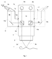
- Fig. 1 shows a schematic front view of the structure of a stereo microscope According to the state of the art.
- the stereomicroscope points two stereo main beam paths 2a and 2b, a main objective 3, the is held above the object or patient 1, a microscope body 4 and a binocular tube 7a with eyepieces 8a and 8b.
- the housing 5 faces the observer with its front side 16, the side 17 is the opposite back.
- two optical Beam splitters 6a and 6b arranged, which come from the respective stereo main beam path 2a and 2b sideways out of the housing 5 block an assistant beam path 10a or 10b.
- the Assistant beam path 10a is by means of the deflection element 6i inside the assistant tube 9a onto the binocular tube 7b deflected and reflected from there into the eyepieces, of which in this one Side view (of the assistant's tube) only the eyepiece 8c is visible.
- the observing assistant is symbolically represented by eye 12. If instead of the left position (solid contour) for the Assistant tube 9a the right position (dashed outline) desired is, the assistant tube 9a from the separation point 13a to the Disconnection point 13b to be reassembled.
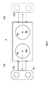
- FIG. 2 shows a stereomicroscope according to the invention in the Side view seen from the right.
- the housing 5 has over a front 16 and a back 17.
- In this side view is only the right stereo main beam path 2b for the right eye 11 of the surgeon.
- the optical beam splitter 6c is like this arranged that the wizard beam path (represented by its Axis 10c) no longer to the side, but through a separation point 13c in the back 17 of the housing 5 is hidden.
- On Assistant tube 9b is at the separation point 13c in a parallel plane 15 to the main stereo beam paths 2a and 2b about the axis 10c pivotally attached.
- An integrated in the assistant tube Deflection element 6g guides the assistant beam path (shown through its axis 10c before the deflection and 10c 'after the Redirection) through an image erecting prism 18 into one Binocular tube 7c with the eyepieces 8d and 8e.
- the binocular tube 7c is arranged on a joint 19 so that it is about the axis 20 is pivotable and also rotatable about the axis 10c '.
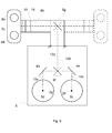
- Fig. 3 shows in a schematic plan view how the optical Beam splitters 6a and 6b in those known from the prior art Devices the main stereo beam paths 2a and 2b to Hide the sides of the housing 5 by means of appropriate separation points 13a or 13b either to the left position (full contour) or the right (dashed outline) of the conventional assistant tube 9a.
- FIG. 4 schematically shows that a A new pivotability of the optical beam splitter 6c by 90 degrees Suppression of an assistant beam path 10c from the stereo main beam path 2b can be achieved.
- the assistant beam path 10c becomes one located on the back 17 Cutting point 13c of the housing 5 supplied. Hiding the Assistant beam path 10a from the stereo main beam path 2a is shown unchanged from the prior art.
- the fact that the Assistant tube 9b is pivotally attached to the separation point 13c, can be left (full contour) or right for the assistant (dashed outline) side position of the assistant.
- the dashed outline is intended according to another inventive Aspect, however, also schematically a swing-out counterweight represent which automatically an imbalance on Counteracts microscope body that by pivoting the Assistant tube from one side to the other.
- Fig. 5 shows schematically an arrangement that has the goal by a separating point arranged centrally on the rear 17 of the housing 5 13d left and one when pivoting the assistant tube 9b right side position for the wizard to achieve that equally far is removed from the housing 5 or from the microscope body. This will achieved by a pair of deflection elements 6e and 6f.
- a pair of deflection elements 6e and 6f Through this Construction is an absolute symmetry with respect to the main binocular tube given.
- Fig. 6 an arrangement is shown schematically, in which from both Stereo main beam paths 2a and 2b by swiveling optical Beam splitters 6c and 6d and deflection elements 6e and 6f, or 6h and 6f the assistant beam paths 10e and 10c of the central separation point 13d are supplied.
- the assistant beam path is the assistant 10d available, which is optionally from the stereo main beam path 2a or 2b comes because the deflecting element 6f is designed switchable.
- the assistant has the Possibility of a 2a or 2b stereo main beam path select and thus optimally the respective content of this Viewing beam paths (e.g. with or without mirrored data).
- Fig. 7 shows both conceivable separation points 13c, 13d, 13e
- the invention are located on the rear 17 of the housing 5, as well as those separation points 13a, 13b, which according to the state of the Technique Hide the assistant beam path to the side.
- the optical beam splitters 6c and 6d by 90 degrees switchable and the deflection elements 6e, 6f and 6h are switchable and / or designed to be pivotable.
- the assistant tube 9b can on a slide rail 14 optionally pushed back and forth between the separation points 13c-e become.
- a variant binds by means of a semicircular slide rail the lateral separation points 13a and 13b with a.
- the The deflection elements 6d and 6c can be pivoted correspondingly radially be adjusted.
Landscapes
- Physics & Mathematics (AREA)
- Chemical & Material Sciences (AREA)
- Analytical Chemistry (AREA)
- General Physics & Mathematics (AREA)
- Optics & Photonics (AREA)
- Microscoopes, Condenser (AREA)
Applications Claiming Priority (2)
| Application Number | Priority Date | Filing Date | Title |
|---|---|---|---|
| US47839403P | 2003-06-13 | 2003-06-13 | |
| US478394P | 2003-06-13 |
Publications (1)
| Publication Number | Publication Date |
|---|---|
| EP1486813A1 true EP1486813A1 (fr) | 2004-12-15 |
Family
ID=33300128
Family Applications (1)
| Application Number | Title | Priority Date | Filing Date |
|---|---|---|---|
| EP04102515A Withdrawn EP1486813A1 (fr) | 2003-06-13 | 2004-06-04 | Microscope stéreoscopique à tube d'observation additionel |
Country Status (4)
| Country | Link |
|---|---|
| US (1) | US7002738B2 (fr) |
| EP (1) | EP1486813A1 (fr) |
| JP (1) | JP2005004222A (fr) |
| DE (1) | DE202004021053U1 (fr) |
Cited By (7)
| Publication number | Priority date | Publication date | Assignee | Title |
|---|---|---|---|---|
| EP1975670A3 (fr) * | 2007-03-30 | 2009-06-03 | Kabushiki Kaisha TOPCON | Fonctionnement de microscope |
| DE102008001352A1 (de) | 2008-04-23 | 2009-10-29 | Leica Microsystems (Schweiz) Ag | Stereomikroskop mit Strahlteilereinrichtung |
| US7894130B2 (en) | 2006-10-27 | 2011-02-22 | Leica Instruments (Singapore) Pte. Ltd. | Stereomicroscope having a beam splitter device |
| DE102009040082A1 (de) | 2009-09-04 | 2011-03-24 | Carl Zeiss Surgical Gmbh | Operationsmikroskop mit optischen Schnittstellen |
| DE102013216476A1 (de) | 2013-08-20 | 2015-02-26 | Carl Zeiss Meditec Ag | Operationsmikroskop mit optischen Schnittstellen |
| DE102005040580B4 (de) | 2005-03-22 | 2018-08-16 | Leica Instruments (Singapore) Pte. Ltd. | 0°-Assistenteneinrichtung mit schwenkbarem Assistentenmodul für ein Mikroskop |
| DE102017217378A1 (de) * | 2017-09-29 | 2019-04-04 | Carl Zeiss Meditec Ag | Vorrichtung zur Auskopplung eines Teiles der Strahlung eines jederzeit frei wählbaren Beobachtungsstrahlenganges eines Binokulars |
Families Citing this family (9)
| Publication number | Priority date | Publication date | Assignee | Title |
|---|---|---|---|---|
| JP4720078B2 (ja) * | 2003-10-27 | 2011-07-13 | 株式会社ニコン | 顕微鏡の鏡筒 |
| JP4754832B2 (ja) * | 2005-01-06 | 2011-08-24 | 株式会社 ニコンビジョン | 実体顕微鏡 |
| JP4786215B2 (ja) * | 2005-04-04 | 2011-10-05 | 株式会社トプコン | 手術用顕微鏡装置 |
| JP2008006089A (ja) * | 2006-06-29 | 2008-01-17 | Mitaka Koki Co Ltd | 手術顕微鏡システム |
| JP5043604B2 (ja) * | 2007-11-07 | 2012-10-10 | 株式会社トプコン | 実体顕微鏡 |
| JP2015515025A (ja) | 2012-04-17 | 2015-05-21 | エンデュア メディカル インコーポレイテッドEndure Medical Inc. | 立体ビーム分割器 |
| DE102012222578A1 (de) | 2012-12-07 | 2014-06-12 | Leica Microsystems (Schweiz) Ag | Operationsmikroskop |
| DE102015216646B4 (de) * | 2015-08-31 | 2022-09-15 | Carl Zeiss Meditec Ag | Vorrichtung für das Erfassen von stereoskopischer Bildinformation sowie System und Verfahren für das stereoskopische Visualisieren eines Objektbereichs |
| JP2018027139A (ja) * | 2016-08-15 | 2018-02-22 | 三鷹光器株式会社 | 手術顕微鏡システム |
Citations (2)
| Publication number | Priority date | Publication date | Assignee | Title |
|---|---|---|---|---|
| US5528426A (en) * | 1994-07-14 | 1996-06-18 | Tti Medical | Laser block beam splitter for microscopes |
| US5552929A (en) * | 1991-07-23 | 1996-09-03 | Olympus Optical Co., Ltd. | Stereomicroscope |
Family Cites Families (6)
| Publication number | Priority date | Publication date | Assignee | Title |
|---|---|---|---|---|
| DE4029638A1 (de) * | 1990-09-19 | 1992-03-26 | Zeiss Carl Fa | Schwenkeinrichtung fuer tragvorrichtungen fuer optische beobachtungsgeraete |
| JPH07218841A (ja) * | 1993-12-07 | 1995-08-18 | Nikon Corp | 顕微鏡 |
| JP3974976B2 (ja) * | 1996-08-21 | 2007-09-12 | オリンパス株式会社 | 鏡筒を有する実体顕微鏡 |
| JP4245750B2 (ja) * | 1999-10-15 | 2009-04-02 | オリンパス株式会社 | 立体観察装置 |
| JP2001208979A (ja) * | 2000-01-27 | 2001-08-03 | Mitaka Koki Co Ltd | 立体顕微鏡 |
| DE50206432D1 (de) * | 2001-02-23 | 2006-05-24 | Leica Microsystems Schweiz Ag | Erweiterte Blendensteuerung für Bildeinblendungen in einem Stereomikroskop |
-
2004
- 2004-03-04 US US10/793,440 patent/US7002738B2/en not_active Expired - Fee Related
- 2004-06-04 EP EP04102515A patent/EP1486813A1/fr not_active Withdrawn
- 2004-06-04 DE DE202004021053U patent/DE202004021053U1/de not_active Expired - Lifetime
- 2004-06-14 JP JP2004175603A patent/JP2005004222A/ja not_active Withdrawn
Patent Citations (2)
| Publication number | Priority date | Publication date | Assignee | Title |
|---|---|---|---|---|
| US5552929A (en) * | 1991-07-23 | 1996-09-03 | Olympus Optical Co., Ltd. | Stereomicroscope |
| US5528426A (en) * | 1994-07-14 | 1996-06-18 | Tti Medical | Laser block beam splitter for microscopes |
Non-Patent Citations (1)
| Title |
|---|
| "The Leica MS1- Surgical microscope system", February 2002, LEICA MICROSYSTEMS LTD., FEBR. 2002, XP002292194 * |
Cited By (12)
| Publication number | Priority date | Publication date | Assignee | Title |
|---|---|---|---|---|
| DE102005040580B4 (de) | 2005-03-22 | 2018-08-16 | Leica Instruments (Singapore) Pte. Ltd. | 0°-Assistenteneinrichtung mit schwenkbarem Assistentenmodul für ein Mikroskop |
| US7894130B2 (en) | 2006-10-27 | 2011-02-22 | Leica Instruments (Singapore) Pte. Ltd. | Stereomicroscope having a beam splitter device |
| EP1975670A3 (fr) * | 2007-03-30 | 2009-06-03 | Kabushiki Kaisha TOPCON | Fonctionnement de microscope |
| US7982949B2 (en) | 2007-03-30 | 2011-07-19 | Kabushiki Kaisha Topcon | Operation microscope having assistant's microscope |
| DE102008001352A1 (de) | 2008-04-23 | 2009-10-29 | Leica Microsystems (Schweiz) Ag | Stereomikroskop mit Strahlteilereinrichtung |
| DE102008001352B4 (de) * | 2008-04-23 | 2009-12-24 | Leica Microsystems (Schweiz) Ag | Stereomikroskop mit Strahlteilereinrichtung |
| US8154795B2 (en) | 2008-04-23 | 2012-04-10 | Leica Instruments (Singapore) Pte. Ltd. | Stereo microscope with beam splitter device |
| DE102009040082A1 (de) | 2009-09-04 | 2011-03-24 | Carl Zeiss Surgical Gmbh | Operationsmikroskop mit optischen Schnittstellen |
| DE102009040082B4 (de) * | 2009-09-04 | 2015-04-09 | Carl Zeiss Meditec Ag | Operationsmikroskop mit optischen Schnittstellen |
| DE102013216476A1 (de) | 2013-08-20 | 2015-02-26 | Carl Zeiss Meditec Ag | Operationsmikroskop mit optischen Schnittstellen |
| DE102017217378A1 (de) * | 2017-09-29 | 2019-04-04 | Carl Zeiss Meditec Ag | Vorrichtung zur Auskopplung eines Teiles der Strahlung eines jederzeit frei wählbaren Beobachtungsstrahlenganges eines Binokulars |
| US11513331B2 (en) | 2017-09-29 | 2022-11-29 | Carl Zeiss Meditec Ag | Device for decoupling part of the radiation of an observation beam path of binoculars that is freely selectable at any time |
Also Published As
| Publication number | Publication date |
|---|---|
| DE202004021053U1 (de) | 2006-08-24 |
| US7002738B2 (en) | 2006-02-21 |
| US20040252371A1 (en) | 2004-12-16 |
| JP2005004222A (ja) | 2005-01-06 |
Similar Documents
| Publication | Publication Date | Title |
|---|---|---|
| EP1326117B1 (fr) | Adaptateur ophtalmoscopique et microscope chirurgical | |
| DE102004050893B4 (de) | Tubus mit zwei umschaltbaren Planoptikelementen zur wahlweisen Strahlengangvertauschung und Bildumkehr für ein Mikroskop sowie Mikroskop | |
| DE102014108811B3 (de) | Stereomikroskop mit einem Hauptbeobachterstrahlengang und einem Mitbeobachterstrahlengang | |
| DE19541420B4 (de) | Stereomikroskop-Anordnung | |
| EP3058413B1 (fr) | Microscope opératoire muni d'interfaces optiques | |
| EP1235094A2 (fr) | Commande de diaphragme étendue pour l'incrustation des images dans un microscope stéreoscopique | |
| DE202004021053U1 (de) | Stereomikroskop mit einem Mitbeobachtertubus | |
| EP0193818A1 (fr) | Stéréomicroscope pour opérations | |
| EP1320779B1 (fr) | Systeme de redressement de l'image, module d'ophtalmoscopie additionnel et microscope d'operation | |
| WO2018210979A1 (fr) | Microscope opératoire comprenant au moins un dispositif de commutation de trajet optique | |
| EP1424582B1 (fr) | Stéréomicroscope | |
| EP1565777A1 (fr) | Dispositif de reflexion d'une trajectoire de faisceau d'observation stereoscopique | |
| DE10255960A1 (de) | Stereomikroskop | |
| DE102009019575A1 (de) | Stereoskopisches optisches Beobachtungsgerät und stereoskopisches optisches Beobachtungssystem | |
| EP1460466B1 (fr) | Microsocope, notamment microscope stéréoscopique | |
| DE102010003640A1 (de) | Video-Stereomikroskop | |
| DE10316242A1 (de) | Umlenksystem für eine Beobachtungseinrichtung sowie Beobachtungseinrichtung | |
| DE102012213369B4 (de) | Stereomikroskop mit vier Beobachtungskanälen | |
| DE19503575B4 (de) | Binokulartubus für ein Stereomikroskop | |
| EP1291696A1 (fr) | Configuration de prismes pour une illumination normale et oblique dans un stéréomicroscope chirurgical | |
| DE102005040473A1 (de) | Stereomikroskop | |
| DE102005040471B4 (de) | Mikroskop | |
| EP1498762A1 (fr) | Microscope | |
| DE102012203266A1 (de) | Mikroskop mit schaltbarem Dokumentations-Strahlengang | |
| DE10332602B3 (de) | Mikroskop |
Legal Events
| Date | Code | Title | Description |
|---|---|---|---|
| PUAI | Public reference made under article 153(3) epc to a published international application that has entered the european phase |
Free format text: ORIGINAL CODE: 0009012 |
|
| AK | Designated contracting states |
Kind code of ref document: A1 Designated state(s): AT BE BG CH CY CZ DE DK EE ES FI FR GB GR HU IE IT LI LU MC NL PL PT RO SE SI SK TR |
|
| AX | Request for extension of the european patent |
Extension state: AL HR LT LV MK |
|
| 17P | Request for examination filed |
Effective date: 20050609 |
|
| AKX | Designation fees paid |
Designated state(s): DE FR GB |
|
| STAA | Information on the status of an ep patent application or granted ep patent |
Free format text: STATUS: THE APPLICATION IS DEEMED TO BE WITHDRAWN |
|
| 18D | Application deemed to be withdrawn |
Effective date: 20060711 |