EP1486835A2 - Anlagesteuerungssystem - Google Patents
Anlagesteuerungssystem Download PDFInfo
- Publication number
- EP1486835A2 EP1486835A2 EP04013720A EP04013720A EP1486835A2 EP 1486835 A2 EP1486835 A2 EP 1486835A2 EP 04013720 A EP04013720 A EP 04013720A EP 04013720 A EP04013720 A EP 04013720A EP 1486835 A2 EP1486835 A2 EP 1486835A2
- Authority
- EP
- European Patent Office
- Prior art keywords
- plant
- value
- control input
- controller
- clutch
- Prior art date
- Legal status (The legal status is an assumption and is not a legal conclusion. Google has not performed a legal analysis and makes no representation as to the accuracy of the status listed.)
- Granted
Links
Images


Classifications
-
- G—PHYSICS
- G05—CONTROLLING; REGULATING
- G05B—CONTROL OR REGULATING SYSTEMS IN GENERAL; FUNCTIONAL ELEMENTS OF SUCH SYSTEMS; MONITORING OR TESTING ARRANGEMENTS FOR SUCH SYSTEMS OR ELEMENTS
- G05B13/00—Adaptive control systems, i.e. systems automatically adjusting themselves to have a performance which is optimum according to some preassigned criterion
- G05B13/02—Adaptive control systems, i.e. systems automatically adjusting themselves to have a performance which is optimum according to some preassigned criterion electric
- G05B13/04—Adaptive control systems, i.e. systems automatically adjusting themselves to have a performance which is optimum according to some preassigned criterion electric involving the use of models or simulators
-
- F—MECHANICAL ENGINEERING; LIGHTING; HEATING; WEAPONS; BLASTING
- F16—ENGINEERING ELEMENTS AND UNITS; GENERAL MEASURES FOR PRODUCING AND MAINTAINING EFFECTIVE FUNCTIONING OF MACHINES OR INSTALLATIONS; THERMAL INSULATION IN GENERAL
- F16D—COUPLINGS FOR TRANSMITTING ROTATION; CLUTCHES; BRAKES
- F16D48/00—External control of clutches
- F16D48/06—Control by electric or electronic means, e.g. of fluid pressure
-
- F—MECHANICAL ENGINEERING; LIGHTING; HEATING; WEAPONS; BLASTING
- F16—ENGINEERING ELEMENTS AND UNITS; GENERAL MEASURES FOR PRODUCING AND MAINTAINING EFFECTIVE FUNCTIONING OF MACHINES OR INSTALLATIONS; THERMAL INSULATION IN GENERAL
- F16D—COUPLINGS FOR TRANSMITTING ROTATION; CLUTCHES; BRAKES
- F16D2500/00—External control of clutches by electric or electronic means
- F16D2500/10—System to be controlled
- F16D2500/104—Clutch
- F16D2500/10406—Clutch position
- F16D2500/10412—Transmission line of a vehicle
-
- F—MECHANICAL ENGINEERING; LIGHTING; HEATING; WEAPONS; BLASTING
- F16—ENGINEERING ELEMENTS AND UNITS; GENERAL MEASURES FOR PRODUCING AND MAINTAINING EFFECTIVE FUNCTIONING OF MACHINES OR INSTALLATIONS; THERMAL INSULATION IN GENERAL
- F16D—COUPLINGS FOR TRANSMITTING ROTATION; CLUTCHES; BRAKES
- F16D2500/00—External control of clutches by electric or electronic means
- F16D2500/10—System to be controlled
- F16D2500/104—Clutch
- F16D2500/10443—Clutch type
- F16D2500/1045—Friction clutch
-
- F—MECHANICAL ENGINEERING; LIGHTING; HEATING; WEAPONS; BLASTING
- F16—ENGINEERING ELEMENTS AND UNITS; GENERAL MEASURES FOR PRODUCING AND MAINTAINING EFFECTIVE FUNCTIONING OF MACHINES OR INSTALLATIONS; THERMAL INSULATION IN GENERAL
- F16D—COUPLINGS FOR TRANSMITTING ROTATION; CLUTCHES; BRAKES
- F16D2500/00—External control of clutches by electric or electronic means
- F16D2500/30—Signal inputs
- F16D2500/302—Signal inputs from the actuator
- F16D2500/3026—Stroke
-
- F—MECHANICAL ENGINEERING; LIGHTING; HEATING; WEAPONS; BLASTING
- F16—ENGINEERING ELEMENTS AND UNITS; GENERAL MEASURES FOR PRODUCING AND MAINTAINING EFFECTIVE FUNCTIONING OF MACHINES OR INSTALLATIONS; THERMAL INSULATION IN GENERAL
- F16D—COUPLINGS FOR TRANSMITTING ROTATION; CLUTCHES; BRAKES
- F16D2500/00—External control of clutches by electric or electronic means
- F16D2500/70—Details about the implementation of the control system
- F16D2500/704—Output parameters from the control unit; Target parameters to be controlled
- F16D2500/70422—Clutch parameters
- F16D2500/70438—From the output shaft
- F16D2500/70442—Output shaft speed
-
- F—MECHANICAL ENGINEERING; LIGHTING; HEATING; WEAPONS; BLASTING
- F16—ENGINEERING ELEMENTS AND UNITS; GENERAL MEASURES FOR PRODUCING AND MAINTAINING EFFECTIVE FUNCTIONING OF MACHINES OR INSTALLATIONS; THERMAL INSULATION IN GENERAL
- F16H—GEARING
- F16H61/00—Control functions within control units of change-speed- or reversing-gearings for conveying rotary motion ; Control of exclusively fluid gearing, friction gearing, gearings with endless flexible members or other particular types of gearing
- F16H2061/0068—Method or means for testing of transmission controls or parts thereof
- F16H2061/0071—Robots or simulators for testing control functions in automatic transmission
-
- F—MECHANICAL ENGINEERING; LIGHTING; HEATING; WEAPONS; BLASTING
- F16—ENGINEERING ELEMENTS AND UNITS; GENERAL MEASURES FOR PRODUCING AND MAINTAINING EFFECTIVE FUNCTIONING OF MACHINES OR INSTALLATIONS; THERMAL INSULATION IN GENERAL
- F16H—GEARING
- F16H61/00—Control functions within control units of change-speed- or reversing-gearings for conveying rotary motion ; Control of exclusively fluid gearing, friction gearing, gearings with endless flexible members or other particular types of gearing
- F16H61/26—Generation or transmission of movements for final actuating mechanisms
- F16H61/28—Generation or transmission of movements for final actuating mechanisms with at least one movement of the final actuating mechanism being caused by a non-mechanical force, e.g. power-assisted
- F16H61/32—Electric motors , actuators or related electrical control means therefor
-
- G—PHYSICS
- G05—CONTROLLING; REGULATING
- G05B—CONTROL OR REGULATING SYSTEMS IN GENERAL; FUNCTIONAL ELEMENTS OF SUCH SYSTEMS; MONITORING OR TESTING ARRANGEMENTS FOR SUCH SYSTEMS OR ELEMENTS
- G05B2219/00—Program-control systems
- G05B2219/30—Nc systems
- G05B2219/41—Servomotor, servo controller till figures
- G05B2219/41145—Digital filter for compensation of servo loop
-
- G—PHYSICS
- G05—CONTROLLING; REGULATING
- G05B—CONTROL OR REGULATING SYSTEMS IN GENERAL; FUNCTIONAL ELEMENTS OF SUCH SYSTEMS; MONITORING OR TESTING ARRANGEMENTS FOR SUCH SYSTEMS OR ELEMENTS
- G05B2219/00—Program-control systems
- G05B2219/30—Nc systems
- G05B2219/41—Servomotor, servo controller till figures
- G05B2219/41222—Modified command filtering
Definitions
- a throttle valve control apparatus adapted to adjust the degree of opening of a throttle valve provided in an intake passage of an engine by using sliding mode control (Japanese Laid-Open Patent Publication No. 2002-318605).
- a plant control system including a filtering device for carrying out predetermined filtering computation on a target output value to calculate a filtering target value that converges to the target output value with a response delay, and control input determiner that uses response specifying control that allows a convergent behavior for a difference between the filtering target value and the output value of the plant to be variably specified so as to calculate a reaching law input based on a switching function value that defines the convergent behavior for the difference, thereby determining a control input value to be supplied to the plant on the basis of the reaching law input.
- changing a specification of the aforesaid filtering process makes it possible to independently set the convergent behavior for a difference between a target output value and an output value of the plant when the target output value changes. Furthermore, changing a specification of the switching function makes it possible to independently set a convergent behavior for a difference between an output value and the target output value when the output value of the plant changes due to disturbance.
- control input determiner calculates an equivalent control input in the response specifying control on the basis of the filtering target value and the output value of the plant, and determines a control input value for the plant on the basis of the equivalent control input.
- a convergent speed of the difference between the filtering target value and the output value of the plant that is specified by the switching function is set to be higher than a speed at which the filtering target value specified in the filtering computation converges to the target output value.
- the plant control system further includes a storage that stores data of a correlation map showing a correlation between the output values of the plant and the reference values of the model parameter that change according to the output values, and the identifier modifies the reference values determined by applying the output values of the plant to the correlation map on the basis of the control input values for the plant and output values of the plant so as to identify the model parameters.
- the above equation (11) applies to a first-order lag filer.
- the filtering target value NC_cmd_f takes a value that converges, with a response delay, to the clutch rotational speed target value NC_cmd after a change when the change takes place in the clutch rotational speed target value NC_cmd.
- the degree of the response delay of the filtering target value NC_cmd_f with respect to the clutch rotational speed target value NC_cmd changes with a set value of the target value filter coefficient POLE_F. If the clutch rotational speed target value NC_cmd remains constant, then the filtering target value NC_cmd_f will be equal to the clutch rotational speed target value NC_cmd.
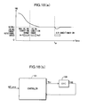
- Fig. 4 is a time series graph showing the operation of the controller 1a, the axis of ordinates indicating the clutch rotational speed (NC, NC_cmd) and the axis of abscissa indicating time (Time).
- the filtering target value NC_cmd_f calculated by the target value filter 11 involves a response delay with respect to the clutch rotational speed target value NC_cmd.
- the follow-up speed of the actual clutch rotational speed NC with respect to the clutch rotational speed target value NC_cmd when the clutch rotational speed target value NC_cmd changes can be independently specified by setting the target filter coefficient POLE_F in the above equation (11).
- the convergent speed for a difference between the clutch rotational speed target value NC_cmd and the actual clutch rotational speed NC can be independently set by setting the switching function setting parameter POLE in the above equation (13).
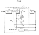
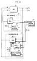
- a controller 1b shown in Fig. 5 differs from the controller 1a shown in Fig. 3 in that the response specifying control unit 10b is not equipped with an adaptation law calculator, while it is equipped with an identifier 20, which corresponds to the identifying means in the present invention.
- the response specifying control unit 10b having the second construction may also be provided with the adaptation law calculator, as in the case of the response specifying control unit 10a having the first construction, to calculate an adaptation law input based on an identified model parameter b1, and then have the adder 17 add the adaptation law input to calculate the clutch stroke Pc1.
- the identifier 21 uses the reference parameters albase and b1base determined by the parameter scheduler 30 to calculate a parameter correction value d ⁇ according to the following equation (30), using a vector ⁇ base defined by the following equation (29), KP calculated according to the above equation (24), and e_id calculated according to the above equation (22).
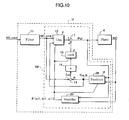
- a controller 1d shown in Fig. 8 differs from the controller 1c shown in Fig. 6 in that a response specifying control unit 10d has an adaptive disturbance observer 50, while it has no identifier. Furthermore, processing in a parameter scheduler 41 is different from that in the parameter scheduler 30 shown in Fig. 6.
- the clutch actuator has a dead time characteristic, so that the factor of a continuous system dead time dc of the clutch actuator is added to the clutch transmission torque Tc.
- the vehicle speed VP and the clutch rotational speed NC are mutually convertible in terms of a gear ratio of a transmission (not shown) connected to the clutch assembly 4 and an outside diameter of tires.
- the drag torque Td may be also divided into a component Td1 that changes according to the clutch rotational speed NC and a component Td2 that changes according to rolling resistance or gradient.
- Td Drag torque
- Td1 Component dependent on clutch rotational speed NC
- Td2 Component dependent on rolling resistance or gradient
- Kd1 Nonlinear coefficient for calculating running drag.
- An adaptation law input calculator 16 calculates an adaptation law input Uadp* according to the following equation (56).
- Uadp*(k) Adaptation law input in k-th control cycle
- Kadp Feedback gain
- the above equation (48) can be represented in the form of the following equation (62) from the vector ⁇ defined by the following equation (60) and the vector ⁇ defined by equation (61).
- ⁇ T ( k ) [ NC ( k -1) Pcl ( k - d 1) 1]
- ⁇ T ( k ) [ a 1( k ) b 1( k ) c 1( k )]
- NC _hat ( k ) ⁇ T ( k - 1) ⁇ ⁇ ( k )
- the reaching law input calculator 15 calculates the reaching law input Urch according to the following equation (67).
- the equivalent control input calculator 12 calculates the equivalent control input Ueq according to the following equation (68).
- clutch OFF completion time TM_CLOFF, gear position change completion time TM_SCHG, and clutch ON completion time TM_CLON are preset on the basis of assumed completion time of each step (TM_CLOFF ⁇ TM_SCHG ⁇ TM_CLON).
- the controller 1c proceeds to STEP110 wherein the controller 1c sets the target slip rate SR_cmd to 0% (clutch ON, no slip).
- the clutch stroke Pcl was determined by the response specifying control unit 10 using the response specifying control.
- response specifying control such as sliding mode control or back-stepping control, may be used.
- Figs. 32A and 32B are explanatory diagrams of the shifting operation in an automated manual transmission
- Fig. 33 shows graphs illustrating changes in disturbance restraining capability caused by changing response specifying parameters
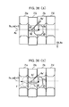
- Figs. 34A and 34B are explanatory diagrams of the shifting operation when a response specifying parameter is changed in the automated manual transmission
- Figs. 35A and 35B are graphs showing displacements of the shift arm and set response specifying parameters in the shifting operation
- Figs. 36A and 36B are explanatory diagrams of the selecting operation in the automated manual transmission
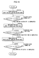
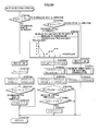
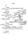
- Fig. 37 and Fig. 38 are flowcharts of a speed changing operation
- Fig. 39 is a flowchart of the shifting/selecting operation
- Fig. 40 and Fig. 41 are flowcharts of calculation of a target value in a rotational synchronizing operation.
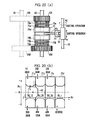
- a third forward gear 63c on the input side and a fourth forward gear 63d on the input side are composed of idle gears rotative with respect to the input shaft 62.
- the corresponding third forward gear 64c on an output side and a fourth forward gear 64d on the output side are formed to be integral with the output shaft 61.
- a third/fourth gear synchronizer 60b switches between two modes, namely, a mode in which the third forward gear 63c on the input side and the fourth forward gear 63d on the input side are selectively connected to the input shaft 62 (speed change established mode) and a mode in which both gears 63c and 63d are disengaged from the input shaft 62 (neutral mode).
- the shift arm 65 is moved in an axial direction or shifting direction parallel to the input shaft 62 by the shift motor 67, the shift arm 65 being in engagement with any one of the shift pieces.
- the shifting arm 65 is positioned at the neutral position or a shifting position where each speed change stage is established.
- the sliding mode controller 113 has a subtracter 122 that uses the following equation (82) to model the construction for positioning the shift arm 65 in the shifting direction in the transmission 80, and calculates a difference E_sc between a filtering target value Psc_cmd_f(k) and a position Psc(k) of the shift arm 65 in the shifting direction, a switching function value calculator 123 calculating a value of a switching function ⁇ _sc, a reaching law input calculator 124 calculating a reaching law input Urch_sc, an adaptation law input calculator 125 calculating an adaptation law input Uadp_sc, an equivalent control input calculator 126 calculating an equivalent control input Ueq_sr, and an adder 127 that adds the equivalent control input Ueq_sr, the reaching law input Urch_sr, and the adaptation law input Uadp_sc so as to obtain a control value Vsl of the voltage to be applied to the shift motor 67.
- the adder 127 calculates a control input Vsc(k) to the shift motor 67 according to the following equation (89).
- Vsc ( k ) Ueq _ sc ( k ) + Urch _ sc ( k ) + Uadp _ sc ( k )
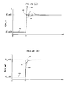
- Fig. 25A and Fig. 25B illustrate a case where the shifting operation is performed using the sliding mode controller 113 having 2 degrees of freedom shown in Fig. 23.
- the graph of Fig. 25A illustrates the case where the shifting operation is performed on a shift mechanism having the same dynamic characteristic as that in Fig. 24A.
- Fig. 25B illustrates the case where the shifting operation is performed on a shift mechanism having the same dynamic characteristic as that in Fig. 24B.
- W(k) the left side of the above equation (93) is defined as W(k), as shown in the following equation (94), while the right side is defined as W_hat(k) as shown in the following equation (95), then W(k) will be a virtual output of a virtual plant 140 shown in Fig. 27. Therefore, W(k) may be considered to denote a model output of the virtual plant 140, and W_hat(k) may be considered to denote a model equation of the virtual plant 140.
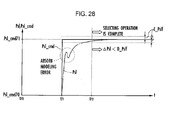
- the number of model parameters to be identified can be reduced, making it possible to achieve a reduced time required for a model parameter to converge to an optimum value.
- the amount of computation is reduced with a resultant shortened computation time, as compared with a case where the identification processing is carried out on all model parameters. This allows a control cycle of the selection controller 111 to be set shorter, leading to improved controllability of the selection controller 111.
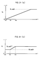
- Fig. 29A is a graph illustrating a behavior of the shift arm 65 observed when the selecting operation is performed using a sliding mode controller of 1 degree of freedom that has no target value filter 131 shown in Fig. 26.
- Fig. 29B is a graph showing a behavior of the shift arm 65 when the selecting operation is performed using a sliding mode controller 115 of 2 degree of freedom shown in Fig. 26.
- x 10 denotes the target position Psl_cmd
- y 10 denotes displacement of the actual position Psl in a selector having a friction characteristic in a predicted standard range
- z 10 denotes displacement of the actual position Psl in a selector having a lower friction than the standard range
- u 10 denotes displacement of the actual position Psl in a selector having a higher friction than the standard range.
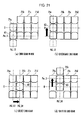
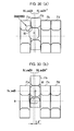
- Fig. 32A illustrates a case where the shift arm 65 has been slightly shifted in the selecting direction because of its interference with the shift piece 71a when the shift arm 65 at the target value Psl_cmd34 of the 3rd/4th gear select position in the AMT is moved to the target value Psc_cmd3 of the 3rd speed shift position.
- the selection controller 111 determines an output voltage Vsl to be applied to the selection motor 66 such that the position of the shift arm 65 in the selecting direction is set back to Psl_cmd34 by eliminating the shift E_sl. This causes a force Fsl to be produced in the selecting direction.
- the chamfered portion causes the shift arm 65 to be slightly shifted in the selecting direction, but to stop moving in the selecting direction at t 112 when Fsc1 and Fsl1 are balanced and also stop moving in the shifting direction. This interrupts the shifting operation, preventing the shift arm 65 from reaching the target value Psc_cmd3 of the 3rd speed shift position.
- the VPOLE_sl calculator 116 of the selection controller 111 calculates different values of VPOLE_sl for the shifting operation and a non-shifting operation (selecting operation), as shown in the following equation (109).
- VPOLE_sl_l -0.95
- VPOLE_sl_h -0.7 so that
- the graphs in Fig. 34B show displacement of the shift arm 65 in Fig. 34A explained above.
- the axes of ordinates indicate the actual position Psc of the shift arm 65 in the shifting direction, the actual position Psl thereof in the selecting direction, and the switching function setting parameter VPOLE_sl from the top.
- the axes of abscissa all indicate time t.
- the controller 1 then proceeds to STEP161 wherein the controller 1 maintains a current gear selection position by holding the target position Psc_cmd of the shift arm 65 in the shifting direction by the shift controller 110 and the target position Psl_cmd of the shift arm 65 in the selecting direction by the selection controller 111 at current values, and then proceeds to STEP133 of Fig. 38.
- the sliding mode controller 113 calculates the equivalent control input Ueq_sc(k), the reaching law input Urch_sc(k), and the adaptation law input Uadp_sc(k) in STEP136 according to the above equations (86) to (88), and further calculates the control input Vsc(k) of voltage applied to the shift motor 67 according to the above equation (89) in STEP137 so as to control the shift motor 67.
- the target position calculator 112 sets Psc_sc to the target position Psc_cmd of the shift arm 65 in the shifting direction, and proceeds to STEP230 wherein the processing for calculation of rotational synchronization target value is terminated.
- the target position calculator 112 sets the target value Psc_cmd of the shift arm 65 in the shifting direction to Psc_end. This increases the level of disturbance restraining capability of the shift controller 110 to prevent the shift arm 65 from overrunning a shift completion position Psc_end.
- the controller 1 then proceeds from STEP243 to STEP230 wherein it ends the processing of the calculation of a rotational synchronization target value.
- the controller includes a target value filter for carrying out filtering computation on a target rotational speed to calculate a filtering target value that converges to the target rotational speed with a response delay, and a response specifying control unit that determines the clutch stroke by response specifying control such that the filtering target value and the clutch rotational speed coincide with each other.
Landscapes
- Engineering & Computer Science (AREA)
- Physics & Mathematics (AREA)
- General Engineering & Computer Science (AREA)
- Software Systems (AREA)
- Evolutionary Computation (AREA)
- Medical Informatics (AREA)
- Health & Medical Sciences (AREA)
- Computer Vision & Pattern Recognition (AREA)
- General Physics & Mathematics (AREA)
- Automation & Control Theory (AREA)
- Fluid Mechanics (AREA)
- Artificial Intelligence (AREA)
- Mechanical Engineering (AREA)
- Feedback Control In General (AREA)
- Hydraulic Clutches, Magnetic Clutches, Fluid Clutches, And Fluid Joints (AREA)
Priority Applications (1)
| Application Number | Priority Date | Filing Date | Title |
|---|---|---|---|
| EP10171262A EP2249216B1 (de) | 2003-06-13 | 2004-06-11 | Anlagesteuerungssystem |
Applications Claiming Priority (6)
| Application Number | Priority Date | Filing Date | Title |
|---|---|---|---|
| JP2003168727 | 2003-06-13 | ||
| JP2003168727 | 2003-06-13 | ||
| JP2003173934A JP2005011036A (ja) | 2003-06-18 | 2003-06-18 | プラントの制御装置 |
| JP2003173934 | 2003-06-18 | ||
| JP2003419798 | 2003-12-17 | ||
| JP2003419798A JP4008410B2 (ja) | 2003-06-13 | 2003-12-17 | プラントの制御装置 |
Related Child Applications (1)
| Application Number | Title | Priority Date | Filing Date |
|---|---|---|---|
| EP10171262.8 Division-Into | 2010-07-29 |
Publications (3)
| Publication Number | Publication Date |
|---|---|
| EP1486835A2 true EP1486835A2 (de) | 2004-12-15 |
| EP1486835A3 EP1486835A3 (de) | 2007-12-05 |
| EP1486835B1 EP1486835B1 (de) | 2011-10-12 |
Family
ID=33303712
Family Applications (2)
| Application Number | Title | Priority Date | Filing Date |
|---|---|---|---|
| EP04013720A Expired - Lifetime EP1486835B1 (de) | 2003-06-13 | 2004-06-11 | Anlagesteuerungssystem |
| EP10171262A Expired - Lifetime EP2249216B1 (de) | 2003-06-13 | 2004-06-11 | Anlagesteuerungssystem |
Family Applications After (1)
| Application Number | Title | Priority Date | Filing Date |
|---|---|---|---|
| EP10171262A Expired - Lifetime EP2249216B1 (de) | 2003-06-13 | 2004-06-11 | Anlagesteuerungssystem |
Country Status (3)
| Country | Link |
|---|---|
| US (1) | US7340336B2 (de) |
| EP (2) | EP1486835B1 (de) |
| CN (1) | CN1573173B (de) |
Cited By (4)
| Publication number | Priority date | Publication date | Assignee | Title |
|---|---|---|---|---|
| WO2007040404A1 (en) * | 2005-10-05 | 2007-04-12 | Kongsberg Automotive As | Method, device and system for controlling an electro-pneumatic actuator |
| EP1798401A3 (de) * | 2005-12-19 | 2009-07-01 | HONDA MOTOR CO., Ltd. | Brennkraftmaschinensteuervorrichtung |
| EP2837842A3 (de) * | 2013-07-30 | 2016-04-20 | Aisin Seiki Kabushiki Kaisha | Klauenkupplungssteuereinheit für Automatikgetriebe |
| EP3171235A1 (de) * | 2015-11-19 | 2017-05-24 | Omron Corporation | Steuerungsvorrichtung, steuerungsverfahren, informationsverarbeitungsprogramm und aufzeichnungsmedium |
Families Citing this family (15)
| Publication number | Priority date | Publication date | Assignee | Title |
|---|---|---|---|---|
| JP4391789B2 (ja) * | 2003-10-03 | 2009-12-24 | 本田技研工業株式会社 | モデルパラメータを部分的に同定する同定器を備えた、プラントを制御する制御装置 |
| TW200706711A (en) * | 2005-08-12 | 2007-02-16 | Komatsu Denshi Kinzoku Kk | Control system and method for time variant system control object having idle time such as single crystal producing device by czochralski method |
| US7444191B2 (en) | 2005-10-04 | 2008-10-28 | Fisher-Rosemount Systems, Inc. | Process model identification in a process control system |
| US8036760B2 (en) * | 2005-10-04 | 2011-10-11 | Fisher-Rosemount Systems, Inc. | Method and apparatus for intelligent control and monitoring in a process control system |
| US7738975B2 (en) * | 2005-10-04 | 2010-06-15 | Fisher-Rosemount Systems, Inc. | Analytical server integrated in a process control network |
| JP4340676B2 (ja) * | 2006-10-11 | 2009-10-07 | 本田技研工業株式会社 | 制御装置 |
| JP4209435B2 (ja) * | 2006-10-19 | 2009-01-14 | 本田技研工業株式会社 | 制御装置 |
| JP4561889B2 (ja) * | 2008-07-01 | 2010-10-13 | トヨタ自動車株式会社 | 出力トルクの算出装置 |
| US8892218B2 (en) | 2010-02-12 | 2014-11-18 | Rockwell Automation Technologies, Inc. | Multiple boolean inputs and outputs for device function blocks |
| US9535413B2 (en) * | 2010-02-12 | 2017-01-03 | Rockwell Automation Technologies, Inc. | Automatic device parameter binding method and system |
| US9134720B2 (en) * | 2010-02-12 | 2015-09-15 | Rockwell Automation Technologies, Inc. | Macro function block for encapsulating device-level embedded logic |
| US8956264B2 (en) * | 2012-06-26 | 2015-02-17 | Ford Global Technologies | Control system and method for a vehicle transmission |
| JP6206320B2 (ja) * | 2014-05-14 | 2017-10-04 | トヨタ自動車株式会社 | クラッチの制御装置 |
| CN110661511B (zh) * | 2019-11-13 | 2021-04-02 | 北京理工大学 | 一种矩阵型自适应滤波器迟滞控制系统及方法 |
| CN112253318B (zh) * | 2020-09-09 | 2021-12-14 | 东风汽车集团有限公司 | 传动间隙自适应反馈控制方法、发动机控制器及汽车 |
Family Cites Families (10)
| Publication number | Priority date | Publication date | Assignee | Title |
|---|---|---|---|---|
| JPH07121209A (ja) | 1993-10-26 | 1995-05-12 | Kobe Steel Ltd | スライディングモード制御系を用いた制御装置 |
| JP3874808B2 (ja) | 1997-03-21 | 2007-01-31 | ガス、テクノロジー、インスティチュート | 吸収冷却機のための改良されたコントロール |
| JP3408754B2 (ja) | 1998-10-02 | 2003-05-19 | 本田技研工業株式会社 | 内燃機関の回転数制御装置 |
| JP3666578B2 (ja) | 2000-08-18 | 2005-06-29 | 株式会社安川電機 | 予測制御装置 |
| CN1110729C (zh) * | 2000-11-22 | 2003-06-04 | 中国航天科技集团公司第五研究院第五○二研究所 | 基于对象特征模型描述的黄金分割智能控制方法 |
| JP3602809B2 (ja) | 2001-05-16 | 2004-12-15 | 本田技研工業株式会社 | プラントの制御装置 |
| JP3995899B2 (ja) | 2001-04-24 | 2007-10-24 | 本田技研工業株式会社 | プラントの制御装置 |
| JP4430270B2 (ja) | 2001-08-06 | 2010-03-10 | 本田技研工業株式会社 | プラントの制御装置及び内燃機関の空燃比制御装置 |
| JP4222816B2 (ja) | 2001-12-06 | 2009-02-12 | 本田技研工業株式会社 | 周波数整形応答指定型制御を用いたプラント制御装置 |
| JP4015589B2 (ja) * | 2003-06-02 | 2007-11-28 | 本田技研工業株式会社 | プラントの制御装置 |
-
2004
- 2004-06-10 US US10/864,552 patent/US7340336B2/en active Active
- 2004-06-11 EP EP04013720A patent/EP1486835B1/de not_active Expired - Lifetime
- 2004-06-11 EP EP10171262A patent/EP2249216B1/de not_active Expired - Lifetime
- 2004-06-14 CN CN2004100592532A patent/CN1573173B/zh not_active Expired - Fee Related
Non-Patent Citations (1)
| Title |
|---|
| None |
Cited By (6)
| Publication number | Priority date | Publication date | Assignee | Title |
|---|---|---|---|---|
| WO2007040404A1 (en) * | 2005-10-05 | 2007-04-12 | Kongsberg Automotive As | Method, device and system for controlling an electro-pneumatic actuator |
| EP1798401A3 (de) * | 2005-12-19 | 2009-07-01 | HONDA MOTOR CO., Ltd. | Brennkraftmaschinensteuervorrichtung |
| US7725237B2 (en) | 2005-12-19 | 2010-05-25 | Honda Motor Co., Ltd. | Control apparatus |
| EP2837842A3 (de) * | 2013-07-30 | 2016-04-20 | Aisin Seiki Kabushiki Kaisha | Klauenkupplungssteuereinheit für Automatikgetriebe |
| EP3171235A1 (de) * | 2015-11-19 | 2017-05-24 | Omron Corporation | Steuerungsvorrichtung, steuerungsverfahren, informationsverarbeitungsprogramm und aufzeichnungsmedium |
| US9977418B2 (en) | 2015-11-19 | 2018-05-22 | Omron Corporation | Control device, control method, information processing program, and recording medium |
Also Published As
| Publication number | Publication date |
|---|---|
| EP1486835B1 (de) | 2011-10-12 |
| US7340336B2 (en) | 2008-03-04 |
| CN1573173A (zh) | 2005-02-02 |
| EP1486835A3 (de) | 2007-12-05 |
| EP2249216B1 (de) | 2011-10-12 |
| CN1573173B (zh) | 2011-06-01 |
| EP2249216A1 (de) | 2010-11-10 |
| US20040260412A1 (en) | 2004-12-23 |
Similar Documents
| Publication | Publication Date | Title |
|---|---|---|
| EP2249216B1 (de) | Anlagesteuerungssystem | |
| US7350433B2 (en) | Transmission control system | |
| WO2014135831A2 (en) | Vehicle clutch control systems | |
| US7231844B2 (en) | Transmission control system | |
| US7222552B2 (en) | Controller for transmission | |
| EP1484654B1 (de) | Regelstrecke mit Kompensation von Störgrössen | |
| EP1536164A2 (de) | System zur Steuerung von Stellgliedern | |
| US7203586B2 (en) | Controller for contact mechanism | |
| JP4008410B2 (ja) | プラントの制御装置 | |
| JP4295074B2 (ja) | 変速機の制御装置 | |
| JP3958738B2 (ja) | 変速機の制御装置 | |
| JP4993409B2 (ja) | パワーユニットの制御装置 | |
| JP4588744B2 (ja) | 変速機の制御装置 | |
| JP3301351B2 (ja) | 制御装置およびその制御装置の設計方法 | |
| JP3859927B2 (ja) | 自動変速機の制御装置 | |
| JP2005011036A (ja) | プラントの制御装置 | |
| JP3816710B2 (ja) | 自動変速機の制御装置 | |
| JP2001227634A (ja) | 自動変速機の制御装置 | |
| JP2001221333A (ja) | 自動変速機の制御装置 |
Legal Events
| Date | Code | Title | Description |
|---|---|---|---|
| PUAI | Public reference made under article 153(3) epc to a published international application that has entered the european phase |
Free format text: ORIGINAL CODE: 0009012 |
|
| AK | Designated contracting states |
Kind code of ref document: A2 Designated state(s): AT BE BG CH CY CZ DE DK EE ES FI FR GB GR HU IE IT LI LU MC NL PL PT RO SE SI SK TR |
|
| AX | Request for extension of the european patent |
Extension state: AL HR LT LV MK |
|
| PUAL | Search report despatched |
Free format text: ORIGINAL CODE: 0009013 |
|
| AK | Designated contracting states |
Kind code of ref document: A3 Designated state(s): AT BE BG CH CY CZ DE DK EE ES FI FR GB GR HU IE IT LI LU MC NL PL PT RO SE SI SK TR |
|
| AX | Request for extension of the european patent |
Extension state: AL HR LT LV MK |
|
| 17P | Request for examination filed |
Effective date: 20071120 |
|
| 17Q | First examination report despatched |
Effective date: 20080111 |
|
| AKX | Designation fees paid |
Designated state(s): DE FR GB |
|
| GRAP | Despatch of communication of intention to grant a patent |
Free format text: ORIGINAL CODE: EPIDOSNIGR1 |
|
| GRAS | Grant fee paid |
Free format text: ORIGINAL CODE: EPIDOSNIGR3 |
|
| GRAA | (expected) grant |
Free format text: ORIGINAL CODE: 0009210 |
|
| RIN1 | Information on inventor provided before grant (corrected) |
Inventor name: SHIMOJO, KANAKOC/O KABUSHIKI KAISHA HONDA GIJUTSU Inventor name: YASUI, YUJIC/O KABUSHIKI KAISHA HONDA GIJUTSU KENK |
|
| AK | Designated contracting states |
Kind code of ref document: B1 Designated state(s): DE FR GB |
|
| REG | Reference to a national code |
Ref country code: GB Ref legal event code: FG4D |
|
| REG | Reference to a national code |
Ref country code: DE Ref legal event code: R096 Ref document number: 602004034779 Country of ref document: DE Effective date: 20111215 |
|
| PLBE | No opposition filed within time limit |
Free format text: ORIGINAL CODE: 0009261 |
|
| STAA | Information on the status of an ep patent application or granted ep patent |
Free format text: STATUS: NO OPPOSITION FILED WITHIN TIME LIMIT |
|
| PGFP | Annual fee paid to national office [announced via postgrant information from national office to epo] |
Ref country code: FR Payment date: 20120619 Year of fee payment: 9 Ref country code: GB Payment date: 20120606 Year of fee payment: 9 |
|
| 26N | No opposition filed |
Effective date: 20120713 |
|
| REG | Reference to a national code |
Ref country code: DE Ref legal event code: R097 Ref document number: 602004034779 Country of ref document: DE Effective date: 20120713 |
|
| REG | Reference to a national code |
Ref country code: DE Ref legal event code: R084 Ref document number: 602004034779 Country of ref document: DE Effective date: 20130211 |
|
| GBPC | Gb: european patent ceased through non-payment of renewal fee |
Effective date: 20130611 |
|
| REG | Reference to a national code |
Ref country code: FR Ref legal event code: ST Effective date: 20140228 |
|
| PG25 | Lapsed in a contracting state [announced via postgrant information from national office to epo] |
Ref country code: GB Free format text: LAPSE BECAUSE OF NON-PAYMENT OF DUE FEES Effective date: 20130611 |
|
| PG25 | Lapsed in a contracting state [announced via postgrant information from national office to epo] |
Ref country code: FR Free format text: LAPSE BECAUSE OF NON-PAYMENT OF DUE FEES Effective date: 20130701 |
|
| PGFP | Annual fee paid to national office [announced via postgrant information from national office to epo] |
Ref country code: DE Payment date: 20230418 Year of fee payment: 20 |
|
| REG | Reference to a national code |
Ref country code: DE Ref legal event code: R071 Ref document number: 602004034779 Country of ref document: DE |