EP1486869A2 - Gerät und Verfahren zur Koprozessorinitialisierung - Google Patents
Gerät und Verfahren zur Koprozessorinitialisierung Download PDFInfo
- Publication number
- EP1486869A2 EP1486869A2 EP04013854A EP04013854A EP1486869A2 EP 1486869 A2 EP1486869 A2 EP 1486869A2 EP 04013854 A EP04013854 A EP 04013854A EP 04013854 A EP04013854 A EP 04013854A EP 1486869 A2 EP1486869 A2 EP 1486869A2
- Authority
- EP
- European Patent Office
- Prior art keywords
- flash memory
- coprocessor
- main
- file system
- auxiliary device
- Prior art date
- Legal status (The legal status is an assumption and is not a legal conclusion. Google has not performed a legal analysis and makes no representation as to the accuracy of the status listed.)
- Withdrawn
Links
Images








Classifications
-
- G—PHYSICS
- G06—COMPUTING OR CALCULATING; COUNTING
- G06F—ELECTRIC DIGITAL DATA PROCESSING
- G06F15/00—Digital computers in general; Data processing equipment in general
- G06F15/16—Combinations of two or more digital computers each having at least an arithmetic unit, a program unit and a register, e.g. for a simultaneous processing of several programs
- G06F15/177—Initialisation or configuration control
-
- G—PHYSICS
- G06—COMPUTING OR CALCULATING; COUNTING
- G06F—ELECTRIC DIGITAL DATA PROCESSING
- G06F9/00—Arrangements for program control, e.g. control units
-
- G—PHYSICS
- G06—COMPUTING OR CALCULATING; COUNTING
- G06F—ELECTRIC DIGITAL DATA PROCESSING
- G06F9/00—Arrangements for program control, e.g. control units
- G06F9/06—Arrangements for program control, e.g. control units using stored programs, i.e. using an internal store of processing equipment to receive or retain programs
- G06F9/44—Arrangements for executing specific programs
- G06F9/4401—Bootstrapping
- G06F9/4405—Initialisation of multiprocessor systems
Definitions
- the present invention relates to an apparatus and method for booting a controller. More particularly, the present invention relates to an apparatus and method for booting a coprocessor for use in a system comprised of a main processor and a coprocessor.
- the main processor controls overall operations of the system, and the coprocessor controls a specific function upon receiving a control signal from the main processor.
- the aforementioned system has been widely used in mobile terminals having current hybrid functions.
- a main processor controls overall operations of a communication or mobile terminal, and a coprocessor performs the processing of video signals upon receiving a control signal from the main processor.
- the aforementioned mobile terminal can be provided with any number of devices, such as a mobile terminal for a camcorder, a PDA (Personal Digital Assistant), a VOD (Video On Demand) phone, and similar devices.
- FIG. 1 A representative example of the aforementioned system, including the main processor and the coprocessor, is shown in Fig. 1. The following detailed description will hereinafter be described with reference to Fig. 1 in which, the example of the aforementioned system is provided as a mobile terminal.
- a first flash memory 110 is comprised of a NOR flash memory for storing boot and loader programs and main operation programs of the main processor 100.
- a second flash memory 120 is comprised of a NAND flash memory for storing large amounts of nonvolatile data, for example, content data, font data, bitmap data, phonebook data, and similar data.
- the second flash memory 120 has a limited number of correction times associated with the same area, such that encounters with an unexpected error in a specified area results in an outcome wherein data cannot be recorded or stored any further in the second flash memory 120. Therefore, a flash file system is adapted to access data of the flash memory (i.e., 110 and 120).
- RAM (Random Access Memory) 130 can be adapted to function as a work memory for use in the main processor 100.
- Other peripheral devices 140 are comprised of devices operated by a control signal generated from the main processor 100. In this case, the peripheral devices 140 can be keypads, displays, RF (Radio Frequency) units, communication units, and similar devices.
- An additional first flash memory 210 is comprised of a NOR flash memory for storing boot and loader programs and main operation programs of the coprocessor 200.
- An additional second flash memory 220 is comprised of a NAND flash memory for storing large amounts of nonvolatile data, for example, content data associated with functions of the coprocessor 200.
- RAM 230 can be adapted as a work memory of the coprocessor 200.
- Other peripheral devices 240 are comprised of devices operated by a control signal generated from the coprocessor 200.
- the peripheral devices 240 can be devices such as multimedia codecs, cameras, displays (e.g., LCDs), and similar devices. Content data stored in the second flash memory 220 can then include video-processed and similar data. If the mobile terminal is a PDA terminal, substantially all the applications, other than a communication function, can be provided by the peripheral devices 240.
- the first flash memories 110 and 210 each can be provided as a NOR flash memory.
- the second flash memories 120 and 220 can be provided as a NAND flash memory.
- the main processor 100 and the coprocessor 200 each include a memory unit comprised of NOR and NAND flash memories and RAMs. Therefore, the main processor 100 and the coprocessor 200 must each include the aforementioned memories, resulting in increased hardware installation space and increased production cost. Therefore, it is preferable for either one of the NOR and NAND flash memories to be removed.
- the NOR flash memory is very expensive, and where it is configured in the form of a stable configuration, it can store boot and loader programs and flash file systems.
- the NAND flash memory has advantages in that it is relatively cheaper than the NOR flash memory, and has excellent capacity which is higher than that of the NOR flash memory.
- the NAND flash memory has a relatively-high probability of creating bad sectors in the memory, in which the memory stores content data for use in a corresponding device. Therefore, when storing the boot and loader programs and flash filter systems in the NAND flash memory, it is impossible to perform operations of an overall system if unexpected bad sectors occur in a specific area for storing the programs.
- the embodiments of the present invention have been made in view of the above problems, and it is an object of the present invention to provide an apparatus and method for removing a relatively high-priced NOR flash memory from a coprocessor, in a system comprised of a main processor and the coprocessor, and enabling the coprocessor to perform a booting function upon receiving a control signal from the main processor.
- an apparatus including a main device and an auxiliary device, comprising in part, the following components.
- the main device can include a main processor, including a ROM (Read Only Memory) and a RAM (Random Access Memory), for controlling overall operations of the main device, a first flash memory for storing principal programs of the main device, a second flash memory for storing content data of the main device, and a RAM acting as a work memory of the main device.
- a main processor including a ROM (Read Only Memory) and a RAM (Random Access Memory), for controlling overall operations of the main device, a first flash memory for storing principal programs of the main device, a second flash memory for storing content data of the main device, and a RAM acting as a work memory of the main device.
- the auxiliary device can include a second flash memory for storing principal programs and content data of the auxiliary device, an external RAM acting as a work memory of the auxiliary device, and a coprocessor for including a ROM and a RAM which store boot, loader, and tiny flash file system code files.
- the coprocessor is further provided for booting the auxiliary device using a boot program stored in the internal ROM when it is initially powered on by the main processor.
- the coprocessor is still further provided for controlling a loader program to load principal programs stored in the second flash memory by operating the tiny flash file system, and for controlling the operations of the auxiliary device.
- the coprocessor is comprised of a processor for operating application programs or specific functions requiring a high speed, for example, a GUI (Graphic User Interface), a multimedia codec, and similar devices.
- GUI Graphic User Interface
- multimedia codec and similar devices.
- the main processor is comprised of a processor for controlling overall operations of a system.
- a processor for controlling overall operations of a system for example, in the case of a mobile terminal, an MSM chip may be adapted as the main processor.
- the boot module is comprised of a software module for initializing operations of a controller to enter a main software routine.
- the loader module is comprised of a software module for initializing a number of necessary modules after performing a booting function, and moving the remaining main software code parts to a specific memory area capable of operating a controller.
- the boot-loader module is comprised of a software module wherein the boot module and the loader module are integrated in one module.
- the flash file system is comprised of a software module for writing data on a NAND flash memory or reading data from the NAND flash memory without generating errors.
- the tiny flash file system is comprised of a minimum software module for reading data from the NAND flash memory without generating errors.
- the tiny flash file system is comprised of a flash file system having a minimum data read function that is capable of guaranteeing integrity of data stored in the NAND flash memory.
- the flash file system is comprised of a file system for overcoming a variety of problems, for example, a problem of generating bad sectors of the NAND flash memory, and an aging problem generated when a specific position is repeatedly used such that further corrections (i.e., higher than a predetermined number of correction times) are made unavailable.
- the flash file system can be used for stably writing or reading data on/from a memory.
- the tiny flash file system can be used where a memory is an equivalent to a NAND flash memory. A detailed description of the NOR flash memory is described in greater detail below.
- the first flash memory is comprised of a NOR flash memory.
- the second flash memory is comprised of a NAND flash memory.
- the embodiments of the present invention remove a flash memory for storing initialization information of a coprocessor from a system, the system including a main processor and the coprocessor, and stores initialization information of the coprocessor in either another memory of the coprocessor, or a memory of the main processor, such that the system initialization is established.
- the memory can be either one of a ROM, a RAM, first and second flash memories, and similar devices.
- the initialization information can be either one of a boot program module, a loader program, a boot loader program, and a tiny flash file system of the coprocessor.
- a main device for use in the embodiments of the present invention can include a main processor for operating overall operations of the main device, a first flash memory for storing the principal programs of the main processor, and a second flash memory for storing content data of the main processor.
- An auxiliary device for use in the embodiments of the present invention can include a coprocessor for controlling overall operations of the auxiliary device, and a second flash memory for storing the principal programs and content data of the auxiliary device.
- Initialization information of the auxiliary device for example, a boot program, a loader program, a boot-loader program, and tiny flash file systems, can be stored in an internal ROM of the coprocessor, an internal ROM of the main processor, the first flash memory or the second flash memory.
- a boot program for example, a boot program, a loader program, a boot-loader program, and tiny flash file systems
- an internal ROM of the coprocessor an internal ROM of the main processor, the first flash memory or the second flash memory.
- the aforementioned initialization information for example, a boot program, a loader program, a boot-loader program, and a tiny flash file system, can be stored in the coprocessor's ROM, the main processor's ROM and/or the main processor's flash memory.
- the flash memory of the main processor can be comprised of NOR and NAND flash memories.
- the boot program, the loader program, the boot-loader program, and the tiny flash file systems are comprised of programs operated in the coprocessor.
- a system booting operation can be performed by a boot program stored in the main processor's memory or the coprocessor's internal ROM, and the principal programs stored in the second flash memory of the coprocessor are loaded by the tiny flash file system, such that operations of the auxiliary device can be performed.
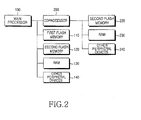
- Fig. 2 is a block diagram illustrating a system comprised of a main processor and a coprocessor in accordance with an embodiment of the present invention. Specifically, Fig. 2 is a block diagram of a system for removing a first flash memory from the coprocessor 200.
- the remaining block diagram configurations, from which the first flash memory is removed from the coprocessor 200, are equal to those of Fig. 1.
- the first flash memory 110, the second flash memory 120, external RAM 130, and other peripheral devices 140 are driven by a control signal received from the main processor 100.
- the first flash memory 110 is comprised of a memory for storing a boot module, a loader module, a flash file system, and other execution program modules of the main processor 100.
- the second flash memory 120 is comprised of a memory for storing nonvolatile data generated by a control signal of the main processor 100, for example, content data, font data, bit data, phonebook data, and similar data.
- the main processor 100 performs its initialization operation using individual software modules stored in the first flash memory 110 when it is initially powered on, and provides the coprocessor 200 with a power-supply voltage such that it is able to initialize the coprocessor 200.
- the first flash memory is removed from the coprocessor 200.
- This first flash memory removed from the coprocessor 200 is comprised of a memory for storing a boot module, a loader module, a flash file system, and other coprocessors' program modules. Therefore, the embodiment of the present invention shown in FIG. 2 distributes the boot module, the loader module, and a tiny flash file system needed to read the data of the NAND flash memory from among the flash file system, and stores the above distributed parts in another memory. Further, upon receiving a control signal from the main processor 100, the embodiment of the present invention initializes the coprocessor 200, and loads/operates the remaining program modules, including a flash file system, using a tiny flash file system.
- the co-processor 200 can perform its booting operation under the following two cases, i.e., a first case in which the coprocessor 200 includes internal ROM and RAM and the internal ROM includes a boot module, a loader module, and a tiny flash file system, and a second case in which the internal ROM includes only boot and loader modules and a tiny flash file system of the coprocessor 200 is included in either the first flash memory 110 or the second flash memory 120.
- the coprocessor 200 can perform its booting operation under the following two cases, i.e., a first case in which the coprocessor 200 includes an internal ROM and the internal ROM includes a boot module, a loader module, and a tiny flash file system, and a second case in which the internal ROM includes only boot and loader modules and a tiny flash file system of the coprocessor 200 is included in either the first flash memory 110 or the second flash memory 120.
- a RAM is included in the coprocessor, and a tiny flash file system is stored in the internal RAM of the coprocessor.
- a RAM is not included in the coprocessor, but is stored in an external RAM of the coprocessor.
- the coprocessor 200 can perform its booting operation in the case where it includes only a RAM, and wherein either the first flash memory 110 or the second flash memory 120 of the main processor 100 includes a boot module, a loader module, and a tiny flash file system of the coprocessor 200.
- the coprocessor 200 can perform its booting operation in the case where it does not include a RAM and a ROM, and wherein either the first flash memory 110 or the second flash memory 120 of the main processor 100 includes a boot module, a loader module, and a tiny flash file system of the coprocessor 200.
- Fig. 3 is a block diagram illustrating an overall system associated with the aforementioned case in which the ROM 203 and the RAM 205 are included in the co-processor 200 in a system comprised of the main processor 100 and the coprocessor 200.
- the coprocessor 200 includes the ROM 203 and the RAM 205.
- the internal ROM 203 stores a boot module, a loader module, and a tiny flash file system of the coprocessor 200, as denoted by 'boot + loader + tiny flash file system'.
- the boot module and the loader module are stored in the internal ROM 203, as denoted by 'boot + loader'.
- the tiny flash file system of the co-processor 200 is stored in either the first flash memory 110 or the second flash memory 120 of the main processor 100.
- Fig. 4 is a flow chart illustrating an initialization procedure of the coprocessor 200 in the case where the ROM 203 and the RAM 205 are included in the coprocessor 200, and the internal ROM 203 stores a boot module, a loader module, and a tiny flash file system of the coprocessor 200.
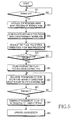
- Fig. 5 is a flow chart illustrating an initialization procedure of the coprocessor 200 in the case where the ROM 203 and the RAM 205 are included in the coprocessor 200, the internal ROM 203 stores the boot and loader modules, and the tiny flash file system of the coprocessor 200 is stored in either the first flash memory 110 or the second flash memory 120.
- the coprocessor 200 if the coprocessor 200 is powered on when the main processor 100 is initialized, it detects the powered-on state at step 311, and gains access to the boot module stored in the internal ROM 203 such that the coprocessor 200 is initialized at step 313.
- a loader module of the coprocessor 200 which is provided for storing the loader module in the second flash memory 220, reads a program code of the coprocessor 200 using a tiny flash file system of the internal ROM 203, and the read program data is stored in the internal RAM 205 at step 315.
- the coprocessor 200 detects this operation completion state at step 317, and a program counter (PC) of the coprocessor 200 jumps to an entrance point of a loaded code area at step 319. The coprocessor 200 then performs main operations at step 321.
- PC program counter
- the coprocessor 200 if the coprocessor 200 is powered on when the main processor 100 is initialized, the coprocessor 200 detects the powered-on state at step 351, and gains access to the boot module stored in the internal ROM 203 such that the coprocessor 200 is initialized at step 353.
- the internal ROM 205 accesses the loader module, and starts communication with the main processor 100 according to a prescribed communication specification at step 355.
- the loader module of the coprocessor 200 requests a transmission message of the tiny flash file system from the main processor 100 at step 357.
- the main processor 100 having received the transmission message of the tiny flash file system, then reads code data of the tiny flash file system of the coprocessor 200 from either the first flash memory 110 or the second flash memory 120 by means of the flash file system of the main processor 100.
- the main processor 100 then transmits the read code data to the loader module of the coprocessor 200 according to a prescribed communication specification.
- the coprocessor 200 detects the reception of the tiny flash file system transferred from the main processor 100 at step 359, and stores the received tiny flash file system code data in the internal RAM 205 at step 361.
- the loader module of the coprocessor 200 which is provided for storing the loader module in the second flash memory 220, reads a program code of the coprocessor 200 using the tiny flash file system stored in the internal RAM 205. The read program data is then stored in the internal RAM 205 at step 363.
- the aforementioned operations are repeated until all of the code for performing basic operations and principal programs is moved to and stored in the internal RAM 205.
- the coprocessor 200 detects this operation completion state at step 365, and a program counter (PC) of the coprocessor 200 jumps to an entrance point of a loaded code area at step 367.
- the coprocessor 200 then performs main operations at step 369.
- PC program counter
- Fig. 6 is a block diagram illustrating an overall system comprised of the main processor 100 and the coprocessor 200 and associated with a specific case in which the ROM 203 is included in the coprocessor 200 and the RAM is not included in the coprocessor 200.
- the coprocessor 200 includes only the ROM 203, wherein the ROM 203 can also be referred to as an internal ROM.
- the internal ROM 203 stores a boot module, a loader module, and a tiny flash file system of the coprocessor 200, as denoted by 'boot + loader + tiny flash file system'.
- the boot module and the loader module are stored in the internal ROM 203, as denoted by 'boot + loader'.
- the tiny flash file system of the coprocessor 200 is stored in either the first flash memory 110 or the second flash memory 120 of the main processor 100.
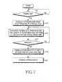
- Fig. 7 is a flow chart illustrating an initialization procedure of the coprocessor 200 in the case where only the ROM 203 is included in the coprocessor 200 and the internal ROM 203 stores a boot module, a loader module, and a tiny flash file system of the coprocessor 200.
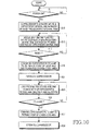
- Fig. 8 is a flow chart illustrating an initialization procedure of the coprocessor 200 in the case where only the ROM 203 is included in the coprocessor 200, the internal ROM 203 stores boot and loader modules, and the tiny flash file system of the coprocessor 200 is stored in either the first flash memory 110 or the second flash memory 120.
- the coprocessor 200 if the coprocessor 200 is powered on when the main processor 100 is initialized, it detects the powered-on state at step 411, and gains access to the boot module stored in the internal ROM 203 such that the coprocessor 200 is initialized at step 413.
- a loader module of the coprocessor 200 which is provided for storing the loader module in the second flash memory 220, reads a program code of the coprocessor 200 using a tiny flash file system of the internal ROM 203, and the read program data is stored in the external RAM 230 at step 415. The aforementioned operations are repeated until a code that is capable of performing basic operations is stored in the external RAM 230.
- the coprocessor 200 After completing the aforementioned operations, the coprocessor 200 detects this operation completion state at step 417, and a program counter (PC) of the coprocessor 200 jumps to an entrance point of a loaded code area at step 419. The coprocessor 200 then performs main operations at step 421.
- PC program counter
- the coprocessor 200 if the coprocessor 200 is powered on when the main processor 100 is initialized, the coprocessor 200 detects the powered-on state at step 451, and gains access to the boot module stored in the internal ROM 203 such that the coprocessor 200 is initialized at step 453.
- the internal ROM 203 accesses the loader module, and starts communication with the main processor 100 according to a prescribed communication specification at step 455.
- the loader module of the coprocessor 200 requests a transmission message of the tiny flash file system from the main processor 100 at step 457.
- the main processor 100 having received the transmission message of the tiny flash file system, then reads code data of the tiny flash file system of the coprocessor 200 from either the first flash memory 110 or the second flash memory 120 by means of the flash file system of the main processor 100.
- the main processor 100 then transmits the read code data to the loader module of the coprocessor 200 according to a prescribed communication specification.
- the loader program of the coprocessor 200 detects the reception of the tiny flash file system which is transferred from the main processor 100 at step 459, and stores the received tiny flash file system code data in the external RAM 230 at step 461.
- the loader module of the coprocessor 200 which is provided for storing the loader module in the second flash memory 220, reads a program code of the coprocessor 200 using the tiny flash file system stored in the external RAM 230, and the read program data is stored in the internal RAM 205 at step 463.
- the coprocessor 200 detects this operation completion state at step 465, and a program counter (PC) of the coprocessor 200 jumps to an entrance point of a loaded code area at step 467. The coprocessor 200 then performs main operations at step 469.
- PC program counter
- Fig. 9 is a block diagram illustrating an overall system comprised of the main processor 100 and the coprocessor 200, which is associated with a specific case in which the internal ROM is not included in the coprocessor 200, and wherein only the RAM 205 is included in the coprocessor 200 in the system.
- the coprocessor 200 includes only the RAM 205, and does not include the ROM.
- either the first flash memory 110 or the second flash memory 120 of the main processor 100 stores a boot module, a loader module, and a tiny flash file system of the coprocessor 200, as denoted by 'boot + loader + tiny flash file system'. Therefore, the coprocessor 200 receives boot and loader modules, and a tiny flash file system from either the first flash memory 110 or the second flash memory 120 of the main processor 100.
- the coprocessor 200 then moves the received data to the internal RAM 205 for storage in the internal RAM 205. Therefore, the coprocessor 200 is booted using the boot and loader modules, and the tiny flash file system stored in the internal RAM 205.
- the coprocessor 200 can then load the principal program codes stored in the second flash memory 220 using the same.
- Fig. 10 is a flow chart illustrating an initialization procedure for use in the coprocessor 200 in the system of Fig. 9.
- the coprocessor 200 detects this powered-on state at step 511, and is initialized to control the internal RAM 205 to be accessed by the main processor 100, while simultaneously remaining in a lock state at step 513.
- the main processor 100 reads code files of the boot module, the loader module, and the tiny flash file system from either the first flash memory 110 or the second flash memory 120, and moves the read code files to the internal RAM 205 of the coprocessor 200 for storage in the RAM 205. Therefore, the internal RAM 205 of the coprocessor 200 stores the boot, loader, and tiny flash file system code files transferred from the main processor 100 at step 513. By repeating the aforementioned operations, the boot, loader, and tiny flash file system code files of the co-processor 200 are stored in the internal RAM 205.
- the main processor 100 After completing the transmission of the boot, loader, and tiny flash file system code files of the coprocessor 200 to either the first flash memory 110 or the second flash memory 120, the main processor 100 then resets the coprocessor 200.
- the main processor 100 can reset the coprocessor using a variety of methods, including for example, a method for recording a specific value in a specific register contained in the coprocessor 200, and a method for applying a signal to a reset terminal exposed to the outside of the coprocessor 200.
- the coprocessor 200 Upon receiving the reset signal at step 517, the coprocessor 200 is reset.
- the internal RAM 205 of the coprocessor 200 stores the boot module, the loader module, and the tiny flash file system code file of the coprocessor 200. Therefore, the coprocessor 200 is reset, and its PC (Program Counter) jumps to the entrance points of the boot, loader, and tiny flash file system code areas at step 519, such that the coprocessor 200 can perform its booting function at step 521.
- the coprocessor 200 then enters a specific state in which the loader can drive a loading process using the tiny flash file system.
- the coprocessor 200 then loads a main program stored in the second flash memory 220 using the tiny flash file system stored in the internal RAM 205 at step 523, and repeats the operation for loading the principal programs stored in the second flash memory 220. After finishing loading of the principal programs, the coprocessor 200 detects the loading completion state at step 525, automatically moves the program counter (PC) to a main program at step 527, and then performs operations of the principal programs at step 529.
- PC program counter
- Fig. 11 is a block diagram illustrating an overall system associated with a specific case in which the coprocessor includes only the external RAM 230, excluding the internal ROM and RAM, and wherein either the first flash memory 110 or the second flash memory 120 stores the boot, loader, and tiny flash file system, as denoted by 'boot + loader + tiny flash file system'.
- the coprocessor 200 includes only the external RAM 230, and does not include the internal ROM and RAM.
- either the first flash memory 110 or the second flash memory 120 of the main processor 100 stores a boot module, a loader module, and a tiny flash file system of the coprocessor 200, as denoted by 'boot + loader + tiny flash file system'.
- the coprocessor 200 moves the boot, loader, and tiny flash file system stored in the main processor 100 to the external RAM 230 for storage in the external RAM 230. Thereafter, the coprocessor 200 is booted using the boot, loader, and tiny flash file system stored in the external RAM 230, and can load the principal program codes stored in the second flash memory 220 using the same.
- Fig. 12 is a flow chart illustrating an initialization procedure for use in the coprocessor 200 in the system of Fig. 10.
- the coprocessor 200 if the coprocessor 200 is powered on when the main processor 100 is initialized, it detects this powered-on state at step 611 and is initialized to control the external RAM 230 to be accessed by the main processor 100 while simultaneously remaining in a lock state at step 613.
- the main processor 100 reads code files of the boot module, the loader module, and the tiny flash file system from either the first flash memory 110 or the second flash memory 120, and moves the read code files to the external RAM 230 of the coprocessor 200 for storage in the external RAM 230. Therefore, the external RAM 230 of the co-processor 200 stores the boot, loader, and tiny flash file system code files transferred from the main processor 100 at step 613. By repeating the aforementioned operations, the boot, loader, and tiny flash file system code files of the coprocessor 200 are stored in the external RAM 230.
- the main processor 100 After finishing the transmission of the boot, loader, and tiny flash file system code files of the coprocessor 200 to either the first flash memory 110 or the second flash memory 120, the main processor 100 resets the coprocessor 200.
- the main processor 100 can reset the coprocessor using a variety of methods, including for example, a method for recording a specific value in a specific register contained in the coprocessor 200, and a method for applying a signal to a reset terminal exposed to the outside of the coprocessor 200.
- the coprocessor 200 Upon receiving the reset signal at step 617, the coprocessor 200 is reset.
- the external RAM 230 of the coprocessor 200 stores the boot, loader, and tiny flash file system code files of the coprocessor 200. Therefore, the coprocessor 200 is reset, and its PC (Program Counter) jumps to the entrance points of the boot, loader, and tiny flash file system code areas at step 619.
- the coprocessor 200 can then perform its booting function at step 621, and enters a specific state in which the tiny flash file system can be operated. Thereafter, the coprocessor 200 loads a main program stored in the second flash memory 220 using the tiny flash file system stored in the external RAM 230 at step 623, and repeats the operation for loading the principal programs stored in the second flash memory 220.
- the coprocessor 200 detects the loading completion state at step 625, automatically moves the program counter (PC) to a main program at step 627, and performs operations of the principal programs at step 629.
- PC Program Counter
- the present invention can remove a NOR flash memory of a coprocessor from the system comprised in part, of a main processor and the coprocessor, resulting in the implementation of small-sized and low-priced system.
- the present invention can store programs stored in the NOR flash memory of the coprocessor in an internal ROM of the coprocessor, an internal ROM of the main processor, and/or a first flash memory, and/or a second flash memory, and move the above programs to a memory of the coprocessor for storage in the memory of the coprocessor, such that the coprocessor can be normally operated.
Landscapes
- Engineering & Computer Science (AREA)
- Theoretical Computer Science (AREA)
- Software Systems (AREA)
- Physics & Mathematics (AREA)
- General Engineering & Computer Science (AREA)
- General Physics & Mathematics (AREA)
- Computer Hardware Design (AREA)
- Computer Security & Cryptography (AREA)
- Stored Programmes (AREA)
- Advance Control (AREA)
- Multi Processors (AREA)
Applications Claiming Priority (2)
| Application Number | Priority Date | Filing Date | Title |
|---|---|---|---|
| KR2003038386 | 2003-06-13 | ||
| KR1020030038386A KR100849296B1 (ko) | 2003-06-13 | 2003-06-13 | 주제어부와 보조제어부를 구비하는 시스템에서의보조제어부의 초기화 장치 및 방법 |
Publications (2)
| Publication Number | Publication Date |
|---|---|
| EP1486869A2 true EP1486869A2 (de) | 2004-12-15 |
| EP1486869A3 EP1486869A3 (de) | 2007-09-05 |
Family
ID=33297396
Family Applications (1)
| Application Number | Title | Priority Date | Filing Date |
|---|---|---|---|
| EP04013854A Withdrawn EP1486869A3 (de) | 2003-06-13 | 2004-06-14 | Gerät und Verfahren zur Koprozessorinitialisierung |
Country Status (4)
| Country | Link |
|---|---|
| US (1) | US7203829B2 (de) |
| EP (1) | EP1486869A3 (de) |
| KR (1) | KR100849296B1 (de) |
| CN (1) | CN1307543C (de) |
Cited By (3)
| Publication number | Priority date | Publication date | Assignee | Title |
|---|---|---|---|---|
| GB2435118A (en) * | 2006-02-09 | 2007-08-15 | Nec Electronics Corp | Method of booting up a slave processor by the boot loader of the slave loading the boot program from the memory attached to the master processor. |
| EP1832977A2 (de) | 2006-03-09 | 2007-09-12 | Telefonaktiebolaget LM Ericsson (publ) | Plattform-Start mit Bridge-Support |
| CN101101558B (zh) * | 2006-07-07 | 2010-06-02 | 国际商业机器公司 | 用于在电力中断后进行初始化的方法和系统 |
Families Citing this family (20)
| Publication number | Priority date | Publication date | Assignee | Title |
|---|---|---|---|---|
| KR100703357B1 (ko) * | 2003-08-16 | 2007-04-03 | 삼성전자주식회사 | 보조제어부를 구비하는 휴대용 단말기의 캐시메모리구현장치 및 방법 |
| JP2005198179A (ja) * | 2004-01-09 | 2005-07-21 | Sanyo Electric Co Ltd | 信号処理装置、信号処理方法及び信号処理プログラム |
| KR100729358B1 (ko) * | 2005-08-29 | 2007-06-15 | 삼성전자주식회사 | 멀티 버퍼 프로그램 스킴을 갖는 플래시 메모리 장치 |
| CN100389420C (zh) * | 2005-09-13 | 2008-05-21 | 北京中星微电子有限公司 | 用协处理器加速文件系统操作的方法及装置 |
| KR101046588B1 (ko) * | 2005-11-16 | 2011-07-06 | 삼성전자주식회사 | 신호처리장치 및 그 제어방법 |
| US8260968B2 (en) * | 2006-01-23 | 2012-09-04 | Lantiq Deutschland Gmbh | Method and system for booting a software package on a network processor |
| US8209527B2 (en) * | 2006-10-26 | 2012-06-26 | Samsung Electronics Co., Ltd. | Memory system and memory management method including the same |
| EP2056593A4 (de) * | 2007-07-18 | 2011-11-30 | Panasonic Corp | Video/audio-verarbeitungsvorrichtung sowie standby- und resetverfahren dafür |
| CN101373434B (zh) * | 2007-08-22 | 2012-01-25 | 国际商业机器公司 | 在多处理器系统中快速加载和运行程序映像的方法和系统 |
| US8706955B2 (en) * | 2011-07-01 | 2014-04-22 | Apple Inc. | Booting a memory device from a host |
| KR102385552B1 (ko) * | 2015-12-29 | 2022-04-12 | 삼성전자주식회사 | 시스템-온-칩 및 이를 포함하는 전자 장치 |
| KR101886176B1 (ko) * | 2016-10-25 | 2018-08-08 | 시큐리티플랫폼 주식회사 | 소유자만 기록 가능한 부트영역을 포함하는 저장장치 |
| JP6831716B2 (ja) * | 2017-03-01 | 2021-02-17 | ルネサスエレクトロニクス株式会社 | 信号処理システム、装置、及びリセット制御方法 |
| US10955872B2 (en) * | 2018-07-25 | 2021-03-23 | Dell Products L.P. | System and method to retain baseboard management controller real-time clock time during BMC reboot |
| CN109460260B (zh) * | 2018-10-24 | 2021-07-09 | 瑞芯微电子股份有限公司 | 一种快速开机的方法和装置 |
| CN109683968B (zh) * | 2018-12-18 | 2022-03-29 | 北京东土军悦科技有限公司 | 交换机快速启动方法、交换机和存储介质 |
| DE102020110970B3 (de) * | 2020-04-22 | 2021-07-22 | Audi Aktiengesellschaft | Steuergerät für eine Benutzerschnittstelle eines Kraftfahrzeugs, Kraftfahrzeug und Verfahren zum Betrieb eines Steuergeräts für eine Benutzerschnittstelle |
| DE102020119172A1 (de) * | 2020-07-21 | 2022-01-27 | Schölly Fiberoptic GmbH | Endoskopanordnung |
| US11238940B1 (en) * | 2020-11-19 | 2022-02-01 | Micron Technology, Inc. | Initialization techniques for memory devices |
| US20240345640A1 (en) * | 2023-04-14 | 2024-10-17 | Aspeed Technology Inc. | Method for resetting processor and computer device |
Citations (3)
| Publication number | Priority date | Publication date | Assignee | Title |
|---|---|---|---|---|
| WO2002075742A1 (en) * | 2001-03-16 | 2002-09-26 | Koninklijke Philips Electronics N.V. | Record carrier and apparatus for scanning the record carrier |
| WO2002095581A2 (en) | 2001-05-19 | 2002-11-28 | International Business Machines Corporation | Electronic system and method for booting of an electronic system |
| US20030050087A1 (en) | 2001-09-07 | 2003-03-13 | Samsung Electronics Co., Ltd. | Memory device in mobile phone |
Family Cites Families (14)
| Publication number | Priority date | Publication date | Assignee | Title |
|---|---|---|---|---|
| JP3310990B2 (ja) * | 1991-04-15 | 2002-08-05 | キヤノン株式会社 | 電子機器 |
| US5754863A (en) * | 1995-01-20 | 1998-05-19 | Redcom Laboratories, Inc. | System for downloading program code to a microprocessor operative as a slave to a master microprocessor |
| US6085307A (en) * | 1996-11-27 | 2000-07-04 | Vlsi Technology, Inc. | Multiple native instruction set master/slave processor arrangement and method thereof |
| US5961631A (en) * | 1997-07-16 | 1999-10-05 | Arm Limited | Data processing apparatus and method for pre-fetching an instruction in to an instruction cache |
| US6505290B1 (en) * | 1997-09-05 | 2003-01-07 | Motorola, Inc. | Method and apparatus for interfacing a processor to a coprocessor |
| US6400717B1 (en) * | 1998-10-16 | 2002-06-04 | Samsung Electronics Co., Ltd. | Device for booting a multiprocessor embedded system and method of operation |
| JP2000137690A (ja) * | 1998-10-29 | 2000-05-16 | Uerubiin:Kk | マルチcpuシステム |
| JP2001043084A (ja) * | 1999-05-24 | 2001-02-16 | Toshiba Microelectronics Corp | プロセッサ装置 |
| KR100325430B1 (ko) * | 1999-10-11 | 2002-02-25 | 윤종용 | 상이한 워드 길이의 산술연산을 수행하는 데이터 처리장치 및 그 방법 |
| US6601167B1 (en) * | 2000-01-14 | 2003-07-29 | Advanced Micro Devices, Inc. | Computer system initialization with boot program stored in sequential access memory, controlled by a boot loader to control and execute the boot program |
| US6604189B1 (en) * | 2000-05-22 | 2003-08-05 | Lsi Logic Corporation | Master/slave processor memory inter accessability in an integrated embedded system |
| JP2002268905A (ja) * | 2001-03-07 | 2002-09-20 | Canon Inc | プログラム動作装置、プログラム書込制御装置、プログラム書込制御方法及び記憶媒体 |
| CN1405679A (zh) * | 2001-04-26 | 2003-03-26 | 德克萨斯仪器股份有限公司 | 多处理器对象控制 |
| CA2426183C (en) * | 2001-08-20 | 2013-02-26 | Samsung Electronics Co., Ltd. | Apparatus and method for interfacing between modem and memory in mobile station |
-
2003
- 2003-06-13 KR KR1020030038386A patent/KR100849296B1/ko not_active Expired - Fee Related
-
2004
- 2004-06-10 US US10/864,459 patent/US7203829B2/en not_active Expired - Fee Related
- 2004-06-14 EP EP04013854A patent/EP1486869A3/de not_active Withdrawn
- 2004-06-14 CN CNB2004100490026A patent/CN1307543C/zh not_active Expired - Fee Related
Patent Citations (3)
| Publication number | Priority date | Publication date | Assignee | Title |
|---|---|---|---|---|
| WO2002075742A1 (en) * | 2001-03-16 | 2002-09-26 | Koninklijke Philips Electronics N.V. | Record carrier and apparatus for scanning the record carrier |
| WO2002095581A2 (en) | 2001-05-19 | 2002-11-28 | International Business Machines Corporation | Electronic system and method for booting of an electronic system |
| US20030050087A1 (en) | 2001-09-07 | 2003-03-13 | Samsung Electronics Co., Ltd. | Memory device in mobile phone |
Cited By (7)
| Publication number | Priority date | Publication date | Assignee | Title |
|---|---|---|---|---|
| GB2435118A (en) * | 2006-02-09 | 2007-08-15 | Nec Electronics Corp | Method of booting up a slave processor by the boot loader of the slave loading the boot program from the memory attached to the master processor. |
| GB2435118B (en) * | 2006-02-09 | 2008-01-09 | Nec Electronics Corp | Multiprocessor system and boot-up method of slave system |
| US7765391B2 (en) | 2006-02-09 | 2010-07-27 | Nec Electronics Corporation | Multiprocessor system and boot-up method of slave system |
| EP1832977A2 (de) | 2006-03-09 | 2007-09-12 | Telefonaktiebolaget LM Ericsson (publ) | Plattform-Start mit Bridge-Support |
| EP1832977A3 (de) * | 2006-03-09 | 2007-10-10 | Telefonaktiebolaget LM Ericsson (publ) | Plattform-Start mit Bridge-Support |
| WO2007101533A3 (en) * | 2006-03-09 | 2007-11-01 | Ericsson Telefon Ab L M | Platform boot with bridge support |
| CN101101558B (zh) * | 2006-07-07 | 2010-06-02 | 国际商业机器公司 | 用于在电力中断后进行初始化的方法和系统 |
Also Published As
| Publication number | Publication date |
|---|---|
| US7203829B2 (en) | 2007-04-10 |
| CN1307543C (zh) | 2007-03-28 |
| KR100849296B1 (ko) | 2008-07-29 |
| CN1573694A (zh) | 2005-02-02 |
| US20040255111A1 (en) | 2004-12-16 |
| EP1486869A3 (de) | 2007-09-05 |
| KR20040107783A (ko) | 2004-12-23 |
Similar Documents
| Publication | Publication Date | Title |
|---|---|---|
| US7203829B2 (en) | Apparatus and method for initializing coprocessor for use in system comprised of main processor and coprocessor | |
| KR100877610B1 (ko) | 페이지 데이터 저장 방법과 저장 장치 | |
| EP2375323A1 (de) | Firmware-Bild-Aktualisierung und -Verwaltung | |
| US7484047B2 (en) | Apparatus and method for composing a cache memory of a wireless terminal having a coprocessor | |
| US20100064036A1 (en) | Peripheral device operation method, peripheral device and host | |
| US20050144364A1 (en) | Memory management method for simultaneously loading and executing program codes | |
| CN111666088A (zh) | Pod的更替方法、装置、电子设备及计算机可读存储介质 | |
| US7793088B2 (en) | Wireless communication device and system startup method for the same | |
| US8171192B2 (en) | Hardware-assisted device configuration detection | |
| US20060047938A1 (en) | Method and apparatus to initialize CPU | |
| CN116028267A (zh) | 双系统安全手机重置方法、装置、服务器及存储介质 | |
| CN112199272B (zh) | 一种智能终端的测试方法、装置、终端设备及介质 | |
| EP4418111A1 (de) | Anwendungsstartverfahren, anwendungsstartsystem, speichermedium und intelligentes endgerät | |
| US8214714B2 (en) | Nonvolatile storage device, controller of nonvolatile memory, and nonvolatile storage system | |
| US20170365359A1 (en) | Methods for operating a data storage device and data storage device utilizing the same | |
| CN117311844A (zh) | 菜单选项修改方法、装置、bios系统、设备及存储介质 | |
| CN112035071B (zh) | 磁盘数据读取方法、装置、计算机设备及存储介质 | |
| US20210354713A1 (en) | Agent control device, agent control method, and storage medium storing agent control program | |
| US8627267B2 (en) | Apparatus and method for initializing system global variables by using multiple load/store instructions | |
| KR101281183B1 (ko) | 무선인터넷 플랫폼모듈의 부트 레이지 로딩 기능이 구비된단말장비 및 그 제어방법 | |
| US20190310797A1 (en) | Controller and memory system including the same | |
| US7761679B2 (en) | Method for recovering from download failure of program and portable terminal employing the method | |
| KR20000033437A (ko) | 부트스트랩로더 기능 구현 장치 | |
| US20220206688A1 (en) | Method for increasing the number of applications in a device having a limited memory | |
| KR100673999B1 (ko) | 이동통신 단말기의 부팅방법 |
Legal Events
| Date | Code | Title | Description |
|---|---|---|---|
| PUAI | Public reference made under article 153(3) epc to a published international application that has entered the european phase |
Free format text: ORIGINAL CODE: 0009012 |
|
| 17P | Request for examination filed |
Effective date: 20040614 |
|
| AK | Designated contracting states |
Kind code of ref document: A2 Designated state(s): AT BE BG CH CY CZ DE DK EE ES FI FR GB GR HU IE IT LI LU MC NL PL PT RO SE SI SK TR |
|
| AX | Request for extension of the european patent |
Extension state: AL HR LT LV MK |
|
| PUAL | Search report despatched |
Free format text: ORIGINAL CODE: 0009013 |
|
| AK | Designated contracting states |
Kind code of ref document: A3 Designated state(s): AT BE BG CH CY CZ DE DK EE ES FI FR GB GR HU IE IT LI LU MC NL PL PT RO SE SI SK TR |
|
| AX | Request for extension of the european patent |
Extension state: AL HR LT LV MK |
|
| AKX | Designation fees paid |
Designated state(s): DE FR GB |
|
| 17Q | First examination report despatched |
Effective date: 20080502 |
|
| RAP1 | Party data changed (applicant data changed or rights of an application transferred) |
Owner name: SAMSUNG ELECTRONICS CO., LTD. |
|
| RIN1 | Information on inventor provided before grant (corrected) |
Inventor name: LIM, CHAE-WHAN C/O SAMSUNG ELECTRONICS CO., LTD |
|
| GRAP | Despatch of communication of intention to grant a patent |
Free format text: ORIGINAL CODE: EPIDOSNIGR1 |
|
| STAA | Information on the status of an ep patent application or granted ep patent |
Free format text: STATUS: THE APPLICATION IS DEEMED TO BE WITHDRAWN |
|
| 18D | Application deemed to be withdrawn |
Effective date: 20130410 |