EP1486947A2 - Appareil de reduction du bruit dans un système de reproduction de son monté sur une automobile - Google Patents
Appareil de reduction du bruit dans un système de reproduction de son monté sur une automobile Download PDFInfo
- Publication number
- EP1486947A2 EP1486947A2 EP04253443A EP04253443A EP1486947A2 EP 1486947 A2 EP1486947 A2 EP 1486947A2 EP 04253443 A EP04253443 A EP 04253443A EP 04253443 A EP04253443 A EP 04253443A EP 1486947 A2 EP1486947 A2 EP 1486947A2
- Authority
- EP
- European Patent Office
- Prior art keywords
- signal
- delay
- noise
- sound
- processing
- Prior art date
- Legal status (The legal status is an assumption and is not a legal conclusion. Google has not performed a legal analysis and makes no representation as to the accuracy of the status listed.)
- Withdrawn
Links
- 230000003321 amplification Effects 0.000 claims description 24
- 238000003199 nucleic acid amplification method Methods 0.000 claims description 24
- 230000005236 sound signal Effects 0.000 claims description 12
- 238000005259 measurement Methods 0.000 claims description 10
- 230000004044 response Effects 0.000 claims description 8
- 230000006866 deterioration Effects 0.000 abstract description 2
- 238000000605 extraction Methods 0.000 abstract 1
- 238000001514 detection method Methods 0.000 description 13
- 230000003247 decreasing effect Effects 0.000 description 7
- 239000000470 constituent Substances 0.000 description 6
- 238000005516 engineering process Methods 0.000 description 5
- 238000006243 chemical reaction Methods 0.000 description 4
- 238000000034 method Methods 0.000 description 4
- 238000002360 preparation method Methods 0.000 description 3
- 230000005540 biological transmission Effects 0.000 description 2
- 238000010276 construction Methods 0.000 description 2
- 238000010586 diagram Methods 0.000 description 2
- 230000015572 biosynthetic process Effects 0.000 description 1
- 230000001934 delay Effects 0.000 description 1
- 230000003111 delayed effect Effects 0.000 description 1
- 230000000694 effects Effects 0.000 description 1
- 239000000284 extract Substances 0.000 description 1
- 230000006870 function Effects 0.000 description 1
- 230000002093 peripheral effect Effects 0.000 description 1
- 238000003786 synthesis reaction Methods 0.000 description 1
Images


Classifications
-
- G—PHYSICS
- G10—MUSICAL INSTRUMENTS; ACOUSTICS
- G10K—SOUND-PRODUCING DEVICES; METHODS OR DEVICES FOR PROTECTING AGAINST, OR FOR DAMPING, NOISE OR OTHER ACOUSTIC WAVES IN GENERAL; ACOUSTICS NOT OTHERWISE PROVIDED FOR
- G10K11/00—Methods or devices for transmitting, conducting or directing sound in general; Methods or devices for protecting against, or for damping, noise or other acoustic waves in general
- G10K11/16—Methods or devices for protecting against, or for damping, noise or other acoustic waves in general
- G10K11/175—Methods or devices for protecting against, or for damping, noise or other acoustic waves in general using interference effects; Masking sound
- G10K11/178—Methods or devices for protecting against, or for damping, noise or other acoustic waves in general using interference effects; Masking sound by electro-acoustically regenerating the original acoustic waves in anti-phase
- G10K11/1785—Methods, e.g. algorithms; Devices
- G10K11/17857—Geometric disposition, e.g. placement of microphones
-
- G—PHYSICS
- G10—MUSICAL INSTRUMENTS; ACOUSTICS
- G10K—SOUND-PRODUCING DEVICES; METHODS OR DEVICES FOR PROTECTING AGAINST, OR FOR DAMPING, NOISE OR OTHER ACOUSTIC WAVES IN GENERAL; ACOUSTICS NOT OTHERWISE PROVIDED FOR
- G10K11/00—Methods or devices for transmitting, conducting or directing sound in general; Methods or devices for protecting against, or for damping, noise or other acoustic waves in general
- G10K11/16—Methods or devices for protecting against, or for damping, noise or other acoustic waves in general
- G10K11/175—Methods or devices for protecting against, or for damping, noise or other acoustic waves in general using interference effects; Masking sound
- G10K11/178—Methods or devices for protecting against, or for damping, noise or other acoustic waves in general using interference effects; Masking sound by electro-acoustically regenerating the original acoustic waves in anti-phase
- G10K11/1787—General system configurations
- G10K11/17879—General system configurations using both a reference signal and an error signal
- G10K11/17881—General system configurations using both a reference signal and an error signal the reference signal being an acoustic signal, e.g. recorded with a microphone
-
- G—PHYSICS
- G10—MUSICAL INSTRUMENTS; ACOUSTICS
- G10K—SOUND-PRODUCING DEVICES; METHODS OR DEVICES FOR PROTECTING AGAINST, OR FOR DAMPING, NOISE OR OTHER ACOUSTIC WAVES IN GENERAL; ACOUSTICS NOT OTHERWISE PROVIDED FOR
- G10K11/00—Methods or devices for transmitting, conducting or directing sound in general; Methods or devices for protecting against, or for damping, noise or other acoustic waves in general
- G10K11/16—Methods or devices for protecting against, or for damping, noise or other acoustic waves in general
- G10K11/175—Methods or devices for protecting against, or for damping, noise or other acoustic waves in general using interference effects; Masking sound
- G10K11/178—Methods or devices for protecting against, or for damping, noise or other acoustic waves in general using interference effects; Masking sound by electro-acoustically regenerating the original acoustic waves in anti-phase
- G10K11/1787—General system configurations
- G10K11/17885—General system configurations additionally using a desired external signal, e.g. pass-through audio such as music or speech
-
- G—PHYSICS
- G10—MUSICAL INSTRUMENTS; ACOUSTICS
- G10K—SOUND-PRODUCING DEVICES; METHODS OR DEVICES FOR PROTECTING AGAINST, OR FOR DAMPING, NOISE OR OTHER ACOUSTIC WAVES IN GENERAL; ACOUSTICS NOT OTHERWISE PROVIDED FOR
- G10K2210/00—Details of active noise control [ANC] covered by G10K11/178 but not provided for in any of its subgroups
- G10K2210/10—Applications
- G10K2210/128—Vehicles
- G10K2210/1282—Automobiles
-
- G—PHYSICS
- G10—MUSICAL INSTRUMENTS; ACOUSTICS
- G10K—SOUND-PRODUCING DEVICES; METHODS OR DEVICES FOR PROTECTING AGAINST, OR FOR DAMPING, NOISE OR OTHER ACOUSTIC WAVES IN GENERAL; ACOUSTICS NOT OTHERWISE PROVIDED FOR
- G10K2210/00—Details of active noise control [ANC] covered by G10K11/178 but not provided for in any of its subgroups
- G10K2210/30—Means
- G10K2210/301—Computational
- G10K2210/3023—Estimation of noise, e.g. on error signals
- G10K2210/30232—Transfer functions, e.g. impulse response
-
- G—PHYSICS
- G10—MUSICAL INSTRUMENTS; ACOUSTICS
- G10K—SOUND-PRODUCING DEVICES; METHODS OR DEVICES FOR PROTECTING AGAINST, OR FOR DAMPING, NOISE OR OTHER ACOUSTIC WAVES IN GENERAL; ACOUSTICS NOT OTHERWISE PROVIDED FOR
- G10K2210/00—Details of active noise control [ANC] covered by G10K11/178 but not provided for in any of its subgroups
- G10K2210/30—Means
- G10K2210/301—Computational
- G10K2210/3048—Pretraining, e.g. to identify transfer functions
Definitions
- the present invention relates to a noise reduction apparatus in a sound reproduction system mounted in a moving vehicle, for example.
- a passenger listens to musical pieces and news broadcasting by using a sound reproduction system such as a compact disk player, an FM radio, or the like, mounted in a moving vehicle such as a wheeled vehicle, a ship, an aircraft, etc
- a sound reproduction system such as a compact disk player, an FM radio, or the like
- a moving vehicle such as a wheeled vehicle, a ship, an aircraft, etc
- cruising noise of the moving vehicle may become annoying.
- the moving vehicle is cruising at a high speed, such a noise becomes extremely large and the musical piece and the speech reproduced and outputted from the sound reproduction system are masked in some case by the noise.
- Patent Reference 1 discloses a technology for reducing noise.
- One of such prior art technologies includes an apparatus that collects noise through a microphone, for example, applies a predetermined delay, reverses and amplifies the noise so delayed, electrically adds it to a musical piece signal from a sound reproduction system and acquires an acoustic output.
- the acoustic output from the loud speaker is spatially synthesized with a noise occurring actually in a sound field space and the noise is thus cancelled.
- Another prior art technology discloses an apparatus that collects noise through a microphone, measures its volume level and adjusts a reproduction output level from a sound reproduction system in accordance with a measurement level.
- the reproduction output level of a musical piece, etc is increased with the increase of the noise level to relatively reduce a mask effect by the noise.
- a noise cancellation operation can be insufficient and fail to provide satisfaction to a listener listening to the musical piece from the sound reproduction system inside a cabin of a moving vehicle.
- these prior art technologies have a main target to cancel the cruising noise collected through the microphone, they cannot effectively cancel noise signal components such as musical pieces other than the musical piece that is reproduced inside the cabin and conversation inside the cabin.
- the acoustic output of the musical piece played back contains these noise signal components and fails to fully satisfy the listener.
- a noise reduction apparatus in a sound reproduction system for reproducing and outputting sound to a sound field based on electric audio signals, comprising first and second microphones arranged in the sound field; a first signal processing means for executing a delay processing and an inversion amplification processing for a first sound field electric signal acquired through the first microphone on the basis of a first delay instruction value and a first gain instruction value; a reproduction output means for reproducing and outputting a superimposed signal acquired by superimposing the electric audio signal to an output signal of the first signal processing means; a second signal processing means for executing a delay processing and an inversion amplification processing for the electric audio signal on the basis of a second delay instruction value and a second gain instruction value; a signal superimposing means for superimposing a second sound field electric signal acquired through the second microphone with an output signal from the second signal processing means; and a feedback control means for controlling the first and second delay instruction values and the first and second gain instruction values in accordance with the magnitude of the output signal from the signal super
- a noise reduction apparatus in a car-mounted sound reproduction system is shown in a block diagram of Fig. 1.
- a microphone 11 as a first microphone (hereinafter called “noise mic 11") is installed inside a cabin of a car 10, for example, and picks up various cruising noises such as engine noise generated from the car 10 and cruising noise of tires.
- a delay circuit 12 is a circuit that delays the cruising noise signal by a predetermined time as a first sound field electric signal obtained through the noise mic 11.
- An inversion amplification circuit 13 reverses a phase of an output signal from the delay circuit 12 and amplifies the output signal at a predetermined degree of amplification, that is, a gain.
- the delay amount in the delay circuit 12 and the gain in the inversion amplification circuit 13 can be freely adjusted in accordance with a first delay instruction value and a first gain instruction value supplied from a later-appearing feedback control circuit 23, respectively.
- These delay circuit 12 and inversion amplification circuit 13 constitute a first signal processing means.
- a signal addition circuit 14 is an addition circuit that electrically adds and synthesizes the output signal from the inversion amplification circuit 13 to and with a musical piece signal from a later-appearing sound reproduction system 16.
- a loud speaker 15 operates as a reproduction output means that converts the electric audio signal outputted from the signal addition circuit 14 to an acoustic output and outputs it inside the cabin of the car 10.
- the number of loud speakers is not particularly limited to one and a construction including a plurality of loud speakers such as a surround system stereo system may be used, too.
- the sound generation apparatus 16 is a car-mounted type sound generation apparatus such as a compact disk player, an FM radio, etc, and outputs electric audio signals such as the musical piece signals to the signal addition circuit 14 and to the delay circuit 17.
- the delay circuit 17 imparts a predetermined delay to the electric audio signals such as the musical piece signal supplied from the sound reproduction system 16.
- An inversion amplification circuit 18 reverses a phase of an output signal from the delay circuit 17 and amplifies the output signal at a predetermined degree of amplification, that is, a gain.
- the delay amount in the delay circuit 17 and the gain in the inversion amplification circuit 18 can be freely adjusted in accordance with a second delay instruction value and a second gain instruction value supplied from a later-appearing feedback control circuit 23.
- These delay circuit 17 and inversion amplification circuit 18 constitute a second signal processing means.
- a microphone 19 as a second microphone is a high directional microphone fitted preferably to a part in the proximity of a concha of a listener 30 listening to a musical piece inside the cabin.
- the ear mic 19 is preferably disposed at a position closer to a driver's seat inside the cabin than the noise mic 11, moreover closer to the concha of the driver. Consequently, the ear mic 19 can collect the sound signals existing in the sound field in the proximity of the concha of the user, that is, the sound signals that may be perceived by the hearing sense of the user.
- the number of each of the noise mic 11 and the ear mic 19 is not limited to the example shown in Fig. 1.
- a signal addition circuit 20 is an addition circuit that electrically adds and synthesizes the output signal from the inversion amplification circuit 18 and the input signal as the second sound field signal acquired through the ear mic 19 and operates as signal superimposing means.
- a low-pass filter 21 (hereinafter merely called “LPF 21") is a low-pass filter that extracts noise signal components contained in the output signal from the signal addition circuit 20.
- the embodiment shown in Fig. 1 uses the low-pass filter (LPF 21) for passing only frequency components below hundreds of Hertz as a constituent element for extracting the noise components contained in the output signal from the signal addition circuit 20.
- LPF 21 low-pass filter
- This is directed to remove ordinarily the cruising noise of the car containing noises of a low frequency band. Therefore, the embodiment of the invention is not limited thereto and a constituent element suitable for each embodiment may of course be used for extracting the noise components corresponding to the LPF 21.
- An analog/digital conversion circuit 22 (hereinafter merely called “ADC 22") converts the output signal from the LPF 21 at a predetermined sample frequency to a digital data having a predetermined bit length.
- the digital data output from the ADC 22 is supplied to the feedback control circuit 23.
- the feedback control circuit 23 as a feedback control means mainly includes a microcomputer, a memory circuit such as ROM and RAM and their peripheral circuits (none of them are shown in the drawing) and controls the apparatus shown in Fig. 1 as a whole.
- the memory circuit stores various programs stipulating the operations of the present apparatus. Each of these programs is executed stepwise at a predetermined timing in synchronism with a clock signal provided to the feedback control circuit 23 and various kinds of operation processing of the present apparatus are executed.
- the feedback control circuit 23 outputs a predetermined delay instruction value, a gain instruction value and various control signals to each of the delay circuits 12 and 17, the inversion amplification circuits 13 and 18 and a later-appearing impulse generation circuit 24.
- the impulse generation circuit 24 generates a pulse for measuring an impulse response inside the cabin of the car 10 in order to determine initial values of the delay amounts to be set to the delay circuits 12 and 17 and the gains to be set to the inversion amplification circuits 13 and 18.
- the impulse generation circuit 24 outputs a pulse signal at a predetermined timing on the basis of the instruction from the feedback control circuit 23.
- the impulse generation circuit 24 and the feedback control circuit 23 constitute an initial value setting means.
- each constituent element of the embodiment shown in Fig. 1 has been explained as hardware that exists discretely but the embodiment of the invention is not limited to such a construction.
- the function of each of these constituent elements may be accomplished by software processing using operational devices such as a DSP.
- (s + a')acos is defined as expressing a conversion value of s + a' as an electric signal to a sound pressure output.
- Symbols B and A are spatially synthesized to a sound pressure C and reach the concha of the listener 30.
- the synthesis in the sound field space offsets the noise A and the sound pressure output A' of the noise cancel signal a' and only S as the sound pressure output of the musical piece signal s remains in the sound pressure C.
- This embodiment generates the musical piece cancel signal s' which has the opposite phase to that of the musical piece signal s and to which a predetermined delay is added, by using the delay circuit 17 and the inversion amplification circuit 18.
- the embodiment electrically synthesizes the electric signal [C0]elec acquired through the ear mic 19 and the musical piece cancel signal s' by using the signal addition circuit 20.
- [C0]elec is defined as a conversion value of the sound pressure C0 to the electric signal.
- the feedback control circuit 23 controls the values of the delay amounts and the gains to be supplied to the delay circuits 12 and 17 and to the inversion amplification circuits 13 and 18.
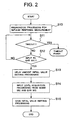
- the initial value setting processing is the processing that sets the initial values of the delay amounts and the gains to be supplied to the delay circuits 12 and 17 and to the inversion amplification circuits 13 and 18 before the execution of the noise cancellation processing. Therefore, the initial value setting processing may well be actuated in synchronism with making of the power source of the sound reproduction system 16 or may well be actuated when the user of the apparatus pushes down a predetermined reset switch.
- the impulse response measurement preparation processing is a preparation processing that measures in advance an impulse response in the sound field space inside the car 10 and determines the initial values of the delay amounts to be set to the delay circuits 12 and 17.
- the feedback control circuit 23 drives the impulse generation circuit 24 in Step S10, lets it generate the pulse for measuring the impulse response, operates a predetermined timer after storing the output timing of such a pulse and proceeds to the next Step S11.
- the feedback control circuit 23 monitors the count value of the timer in Step S11, recognizes that any trouble occurs in the microphones and other constituent elements when time-out occurs after the passage of a predetermined set time and finishes the initial value setting processing shown in Fig. 2.
- Step S11 When time-out is not detected in Step S11, the feedback control circuit 23 proceeds to Step S12 and judges whether or not the signal by the measurement pulse reaches the ear mic 19. When the signal does not reach the ear mic 19, the flow returns to Step S11 and when it does, the flow proceeds to Step S13.
- Step S13 the feedback control circuit 23 first stores the input timing at which the signal reaches the ear mic 19.
- the impulse response inside the car 10 is calculated from the time difference between the input timing and the output timing of the pulse stored in Step S10 and the delay amount of the audio signal during propagation is calculated.
- Step S10 To improve the accuracy of the impulse response measurement, it is also possible to measure in advance the noise in the proximity of the mic in Step S10, then to subtract such a measurement value from the input of the ear mic 19 and to detect the input timing of the pulse signal at the ear mic 19.
- the feedback control circuit 23 makes a predetermined correction for the delay amount so calculated, determines the delay amounts required for the delay circuits 12 and 17 and sets these values as the initial values of the delay amounts of the respective circuits.
- the feedback control circuit 23 After finishing the setting processing of the initial values of the delay amounts in Step S13, the feedback control circuit 23 proceeds to the next Step S14 and measures the input level of each of the noise mic 11 and the ear mic 19. In the next Step S15, the feedback control circuit 23 calculates the gains necessary for the inversion amplification circuits 13 and 18 on the basis of the input levels measured in Step S14 and sets these values as the initial values of the gains of the respective circuits. After finishing the processing described above, the feedback control circuit 23 finishes the initial value setting processing shown in Fig. 2.
- the initial values of the delay amount and the gain of the delay circuits and the inversion amplification circuits are determined by the measurement in the initial value setting processing but the embodiment of the invention is not particularly limited thereto.
- correct measurement may be conducted in advance for typical car models to determine each initial value and the initial value so obtained is stored into the memory of the feedback control circuit 23 so that the user selects the car model in the initial value setting processing and the initial value can be set as the initial value of each of the delay amount and the gain.
- the noise cancellation processing may be executed in a predetermined time interval during the operation of the sound reproduction system 16 after the initial value setting processing is completed or may be executed whenever the change of the mode such as the change of a reproduction source or a volume operation occurs in the sound reproduction system 16.
- Step S20 in Fig. 3 the feedback control circuit 23 detects the residual noise component e contained in the output of the LPF 21 and judges whether or not the detection value is below a predetermined threshold value stored in the memory of the feedback control circuit 23 (Step S21).
- Step S21 When the detection value is judged as being below the threshold value in Step S21, the feedback control circuit 23 returns to Step S20 and repeats the processing described above. When the detection value is judged as exceeding the predetermined threshold value in Step S21, the flow proceeds to Step S22.
- Step S22 the feedback control circuit 23 first outputs a predetermined gain instruction value to the inversion amplification circuits 13 and 18 and adjusts the gain set to each of these circuits.
- various control procedures may be employed. For example, the gains of both circuits are increased or decreased or are changed relatively to each other.
- Various control procedures may be employed in such a fashion as to correspond to the form of practical execution.
- Step S22 When the gain control processing in Step S22 is completed, the feedback control circuit 23 proceeds to the next Step S23, again detects the residual noise component contained in the LPF 21, compares this detection value with the previous detection value and calculates the change rate of the detection value. When the change rate is judged as increasing in the next Step S24, the feedback control circuit 23 returns to Step S22 and repeats the gain control processing. Incidentally, re-control of the gain is of course made in this case in the opposite direction to the direction of previous control from the principle of negative feedback control.
- Step S25 judges whether or not the decrement width of the change rate is below a predetermined value stored in advance inside the memory of the feedback control circuit 23.
- the feedback control circuit 23 returns to Step S22 and repeats the gain control processing.
- Step S25 When the change rate of the detection value is judged as being below the predetermined value in Step S25, on the other hand, the feedback control circuit 23 proceeds to Step S26, outputs the predetermined delay instruction values to the delay circuits 12 and 17 and controls the delay amounts set to these delay circuits.
- control procedures may be employed. For example, the delay amounts of both circuits are increased or decreased or are changed relatively to each other. Various control procedures may be employed in such a fashion as to correspond to the form of practical execution.
- Step S26 When the control processing of the delay amount in Step S26 is completed, the feedback control circuit 23 proceeds to the next Step S27, again detects the residual noise component contained in the LPF 21, compares this detection value with the previous detection value and calculates the change rate of the detection value. When the change rate is judged as increasing in the next Step S28, the feedback control circuit 23 returns to Step S26 and repeats the delay amount control processing. Incidentally, re-control of the delay amounts is of course made in this case in the opposite direction to the direction of previous control from the principle of negative feedback control.
- Step S28 when the change rate of the detection value is judged as decreasing in Step S28, the feedback control circuit 23 proceeds to Step S29 and judges whether or not the decrement width of the change rate is below a predetermined value stored in advance inside the memory of the feedback control circuit 23.
- the gain control circuit 23 returns to Step S26 and repeats the delay amount control processing.
- Step S29 when the change rate of the detection value is judged as decreasing in Step S29, the feedback control circuit 23 returns to Step S20 as the start of the noise cancellation processing and repeats the processing described above.
- the form of the noise cancellation processing in the invention is not limited to the one shown in Fig. 3.
- the delay amount control processing may be conducted before the gain control processing or may be conducted simultaneously with the gain control processing to detect the residual noise component.
- correction of the sound field may be made, too, by taking the cruising noise inside the cabin into account on the basis of the measurement of the frequency characteristics inside the cabin described already besides the cancellation processing of the cruising noise.
Landscapes
- Physics & Mathematics (AREA)
- Engineering & Computer Science (AREA)
- Acoustics & Sound (AREA)
- Multimedia (AREA)
- Health & Medical Sciences (AREA)
- Audiology, Speech & Language Pathology (AREA)
- General Health & Medical Sciences (AREA)
- Soundproofing, Sound Blocking, And Sound Damping (AREA)
- Fittings On The Vehicle Exterior For Carrying Loads, And Devices For Holding Or Mounting Articles (AREA)
Applications Claiming Priority (2)
| Application Number | Priority Date | Filing Date | Title |
|---|---|---|---|
| JP2003168404 | 2003-06-12 | ||
| JP2003168404A JP2005004013A (ja) | 2003-06-12 | 2003-06-12 | ノイズ低減装置 |
Publications (1)
| Publication Number | Publication Date |
|---|---|
| EP1486947A2 true EP1486947A2 (fr) | 2004-12-15 |
Family
ID=33296889
Family Applications (1)
| Application Number | Title | Priority Date | Filing Date |
|---|---|---|---|
| EP04253443A Withdrawn EP1486947A2 (fr) | 2003-06-12 | 2004-06-10 | Appareil de reduction du bruit dans un système de reproduction de son monté sur une automobile |
Country Status (3)
| Country | Link |
|---|---|
| US (1) | US20040252846A1 (fr) |
| EP (1) | EP1486947A2 (fr) |
| JP (1) | JP2005004013A (fr) |
Cited By (2)
| Publication number | Priority date | Publication date | Assignee | Title |
|---|---|---|---|---|
| WO2007115875A1 (fr) * | 2006-04-10 | 2007-10-18 | Robert Bosch Gmbh | Arrangement de restitution de bruits aériens |
| CN107464552A (zh) * | 2017-08-24 | 2017-12-12 | 徐银海 | 一种分布式车载主动降噪系统及方法 |
Families Citing this family (20)
| Publication number | Priority date | Publication date | Assignee | Title |
|---|---|---|---|---|
| JP2009510503A (ja) * | 2005-09-27 | 2009-03-12 | アノクシス・アーゲー | 活性ノイズの減少のための方法及び該方法を動作させるための装置 |
| US20070188308A1 (en) * | 2006-02-14 | 2007-08-16 | Lavoie Bruce S | Vehicular indicator audio controlling |
| JP2008032767A (ja) * | 2006-07-26 | 2008-02-14 | Matsushita Electric Ind Co Ltd | 能動騒音低減システム |
| JP4977551B2 (ja) * | 2007-08-13 | 2012-07-18 | 本田技研工業株式会社 | 能動型騒音制御装置 |
| EP2247121A4 (fr) * | 2008-01-17 | 2012-11-28 | Pioneer Corp | Dispositif de correction de caractéristique de haut-parleur, procédé de correction de caractéristique de haut-parleur et programme de correction de caractéristique de haut-parleur |
| JP4881896B2 (ja) * | 2008-02-26 | 2012-02-22 | ソニー株式会社 | ノイズキャンセル装置、ノイズキャンセル方法 |
| US20090276412A1 (en) * | 2008-04-30 | 2009-11-05 | Nokia Corporation | Method, apparatus, and computer program product for providing usage analysis |
| US8831936B2 (en) * | 2008-05-29 | 2014-09-09 | Qualcomm Incorporated | Systems, methods, apparatus, and computer program products for speech signal processing using spectral contrast enhancement |
| US8538749B2 (en) | 2008-07-18 | 2013-09-17 | Qualcomm Incorporated | Systems, methods, apparatus, and computer program products for enhanced intelligibility |
| US9202456B2 (en) * | 2009-04-23 | 2015-12-01 | Qualcomm Incorporated | Systems, methods, apparatus, and computer-readable media for automatic control of active noise cancellation |
| US9053697B2 (en) | 2010-06-01 | 2015-06-09 | Qualcomm Incorporated | Systems, methods, devices, apparatus, and computer program products for audio equalization |
| EP2551846B1 (fr) | 2011-07-26 | 2022-01-19 | AKG Acoustics GmbH | Reproduction de sons réduisant le bruit |
| US9491537B2 (en) | 2011-07-26 | 2016-11-08 | Harman Becker Automotive Systems Gmbh | Noise reducing sound reproduction system |
| US9735751B1 (en) * | 2012-01-09 | 2017-08-15 | Skullcandy, Inc. | Audio reproduction device target sound signature |
| JP6054697B2 (ja) * | 2012-09-28 | 2016-12-27 | 本田技研工業株式会社 | 車両用音声処理装置 |
| CN105378826B (zh) | 2013-05-31 | 2019-06-11 | 诺基亚技术有限公司 | 音频场景装置 |
| US10446168B2 (en) * | 2014-04-02 | 2019-10-15 | Plantronics, Inc. | Noise level measurement with mobile devices, location services, and environmental response |
| ITUB20160997A1 (it) * | 2016-02-23 | 2017-08-23 | Prinoth Spa | Sistema di riduzione del rumore per un veicolo cingolato e veicolo cingolato |
| US10096311B1 (en) | 2017-09-12 | 2018-10-09 | Plantronics, Inc. | Intelligent soundscape adaptation utilizing mobile devices |
| JP7181848B2 (ja) * | 2019-09-19 | 2022-12-01 | 株式会社奥村組 | アクティブ消音装置及びアクティブ消音方法 |
Family Cites Families (3)
| Publication number | Priority date | Publication date | Assignee | Title |
|---|---|---|---|---|
| JP2924496B2 (ja) * | 1992-09-30 | 1999-07-26 | 松下電器産業株式会社 | 騒音制御装置 |
| JP2843278B2 (ja) * | 1995-07-24 | 1999-01-06 | 松下電器産業株式会社 | 騒音制御型送受話器 |
| SE518116C2 (sv) * | 1999-11-30 | 2002-08-27 | A2 Acoustics Ab | Anordning för aktiv ljudkontroll i ett utrymme |
-
2003
- 2003-06-12 JP JP2003168404A patent/JP2005004013A/ja not_active Withdrawn
-
2004
- 2004-06-08 US US10/862,310 patent/US20040252846A1/en not_active Abandoned
- 2004-06-10 EP EP04253443A patent/EP1486947A2/fr not_active Withdrawn
Cited By (2)
| Publication number | Priority date | Publication date | Assignee | Title |
|---|---|---|---|---|
| WO2007115875A1 (fr) * | 2006-04-10 | 2007-10-18 | Robert Bosch Gmbh | Arrangement de restitution de bruits aériens |
| CN107464552A (zh) * | 2017-08-24 | 2017-12-12 | 徐银海 | 一种分布式车载主动降噪系统及方法 |
Also Published As
| Publication number | Publication date |
|---|---|
| JP2005004013A (ja) | 2005-01-06 |
| US20040252846A1 (en) | 2004-12-16 |
Similar Documents
| Publication | Publication Date | Title |
|---|---|---|
| EP1486947A2 (fr) | Appareil de reduction du bruit dans un système de reproduction de son monté sur une automobile | |
| US10607592B2 (en) | Noise reducing device, noise reducing method, noise reducing program, and noise reducing audio outputting device | |
| EP2494792B1 (fr) | Système et procédé d'amélioration de la qualité de la parole | |
| JP4767166B2 (ja) | ハウリング抑圧装置、プログラム、集積回路、およびハウリング抑圧方法 | |
| JP3353701B2 (ja) | 自己発話検出装置、音声入力装置および補聴器 | |
| US20100142719A1 (en) | Acoustic apparatus and method of controlling an acoustic apparatus | |
| KR20160130832A (ko) | 트랜스듀서 상태의 검출에 기초하여 오디오 트랜스듀서의 성능을 향상시키는 방법들 및 시스템들 | |
| JP2003264883A (ja) | 音声処理装置および音声処理方法 | |
| US8600078B2 (en) | Audio signal amplitude adjusting device and method | |
| CN115334400B (zh) | 一种用于对耳机的接近度检测的集成电路及耳机 | |
| US6813577B2 (en) | Speaker detecting device | |
| JP4435232B2 (ja) | オーディオシステム | |
| JP2000102098A (ja) | 補聴器等の耳装着用外来音処理装置 | |
| US11849284B2 (en) | Feedback control using a correlation measure | |
| TW200701818A (en) | Recording device and adjustment method of audio input signals of the recording device | |
| JP2541062B2 (ja) | 音響再生装置 | |
| JP2007110532A (ja) | 騒音キャンセルヘッドフォン、及びそのフィードバックループゲインばらつき調整方法 | |
| JP2007110535A (ja) | 騒音キャンセルヘッドフォン、及びそのばらつき調整方法 | |
| JP2007108522A (ja) | 騒音キャンセルヘッドフォン、及びそのばらつき調整方法 | |
| JP2007110536A (ja) | 騒音キャンセルヘッドフォン、及びその視聴方法 | |
| JP2011024058A (ja) | 自動音量制御装置 | |
| JP2001044777A (ja) | 車載オーディオ装置 | |
| JP2007110531A (ja) | 騒音キャンセルヘッドフォン、及びその制御ループゲインのばらつき調整方法 | |
| JPH03106199A (ja) | 再生音制御装置 | |
| JP2007110533A (ja) | 1ビット処理による騒音キャンセルヘッドフォン、及び騒音キャンセル方法 |
Legal Events
| Date | Code | Title | Description |
|---|---|---|---|
| PUAI | Public reference made under article 153(3) epc to a published international application that has entered the european phase |
Free format text: ORIGINAL CODE: 0009012 |
|
| 17P | Request for examination filed |
Effective date: 20040705 |
|
| AK | Designated contracting states |
Kind code of ref document: A2 Designated state(s): AT BE BG CH CY CZ DE DK EE ES FI FR GB GR HU IE IT LI LU MC NL PL PT RO SE SI SK TR |
|
| AX | Request for extension of the european patent |
Extension state: AL HR LT LV MK |
|
| STAA | Information on the status of an ep patent application or granted ep patent |
Free format text: STATUS: THE APPLICATION HAS BEEN WITHDRAWN |
|
| 18W | Application withdrawn |
Effective date: 20071031 |