EP1487002A2 - Elektrische Fernbedienung - Google Patents
Elektrische Fernbedienung Download PDFInfo
- Publication number
- EP1487002A2 EP1487002A2 EP04002046A EP04002046A EP1487002A2 EP 1487002 A2 EP1487002 A2 EP 1487002A2 EP 04002046 A EP04002046 A EP 04002046A EP 04002046 A EP04002046 A EP 04002046A EP 1487002 A2 EP1487002 A2 EP 1487002A2
- Authority
- EP
- European Patent Office
- Prior art keywords
- lever
- handle
- microswitch
- circuit breaker
- actuation
- Prior art date
- Legal status (The legal status is an assumption and is not a legal conclusion. Google has not performed a legal analysis and makes no representation as to the accuracy of the status listed.)
- Withdrawn
Links
Images






Classifications
-
- H—ELECTRICITY
- H01—ELECTRIC ELEMENTS
- H01H—ELECTRIC SWITCHES; RELAYS; SELECTORS; EMERGENCY PROTECTIVE DEVICES
- H01H5/00—Snap-action arrangements, i.e. in which during a single opening operation or a single closing operation energy is first stored and then released to produce or assist the contact movement
- H01H5/04—Energy stored by deformation of elastic members
- H01H5/14—Energy stored by deformation of elastic members by twisting of torsion members
- H01H5/16—Energy stored by deformation of elastic members by twisting of torsion members with auxiliary means for temporarily holding parts until torsion member is sufficiently strained
-
- H—ELECTRICITY
- H01—ELECTRIC ELEMENTS
- H01H—ELECTRIC SWITCHES; RELAYS; SELECTORS; EMERGENCY PROTECTIVE DEVICES
- H01H71/00—Details of the protective switches or relays covered by groups H01H73/00 - H01H83/00
- H01H71/10—Operating or release mechanisms
- H01H71/66—Power reset mechanisms
- H01H71/70—Power reset mechanisms actuated by electric motor
-
- H—ELECTRICITY
- H01—ELECTRIC ELEMENTS
- H01H—ELECTRIC SWITCHES; RELAYS; SELECTORS; EMERGENCY PROTECTIVE DEVICES
- H01H71/00—Details of the protective switches or relays covered by groups H01H73/00 - H01H83/00
- H01H71/10—Operating or release mechanisms
- H01H71/12—Automatic release mechanisms with or without manual release
- H01H71/46—Automatic release mechanisms with or without manual release having means for operating auxiliary contacts additional to the main contacts
-
- H—ELECTRICITY
- H01—ELECTRIC ELEMENTS
- H01H—ELECTRIC SWITCHES; RELAYS; SELECTORS; EMERGENCY PROTECTIVE DEVICES
- H01H9/00—Details of switching devices, not covered by groups H01H1/00 - H01H7/00
- H01H9/20—Interlocking, locking, or latching mechanisms
- H01H9/28—Interlocking, locking, or latching mechanisms for locking switch parts by a key or equivalent removable member
- H01H9/281—Interlocking, locking, or latching mechanisms for locking switch parts by a key or equivalent removable member making use of a padlock
Definitions
- the present invention relates to an electrical remote actuation device.
- the master switches may be located in places that are not easily accessible, such as cabinets and the like, or in any case at a distance from operators.
- Remote actuations must meet certain fundamental requirements, such as the ability to apply the force required to operate the levers and to do so with sufficient speed.
- the aim of the present invention is to provide an electrical remote actuation device that is improved with respect to devices of the background art.
- an object of the invention is to provide a remote actuation device that is particularly compact.
- Another object of the invention is to provide a device that offers the greatest assurances of safety and reliability in operation.
- Another object is to provide a device that can be integrated perfectly with existing electrical units.
- an electrical remote actuation device including an electric motor that is suitable to actuate, through a control mechanism, the rotation of an actuation shaft that is associated with a kinematic system for the actuation of an electrical circuit breaker, characterized in that the control mechanism includes a preloaded spring that is suitable to provide the actuation shaft with the impulse to open or close the circuit breaker.
- a device according to the invention includes a containment body 2, which has the classic standardized configuration and forms, at its rear face, a means 3 for coupling to an omega-shaped rail (not shown), according to DIN standards.
- the containment body 2 has, at its front face, a protrusion 4 that contains the actuation assembly of a handle lever 20, which in turn actuates a handle bar 54 that has a triangular cross-section, protrudes in a per se known manner from the containment body 2, and is associated with the lever for actuating the circuit breaker, not shown, that is coupled to the device.
- An electric motor 30 actuates a worm screw 45 that engages a gear 40 that is coaxial to the handle lever 20, together with a spring support 41 for a coiled spring 28, and with a pawl 13 that cooperates, in operation, with a release cam 8 that is pivoted on a release cam pivot 31.
- the lever actuation unit further includes a driving wheel 39, which is also coaxial to the handle lever and to the bar 54 and is suitable to actuate a self-powering lever 17, which in turn acts on a pushbutton 61 of a self-powering microswitch 60.
- the handle lever 20 is connected, by means of a handle cross-member 42, to an engagement lever 16 that is suitable act on a microswitch lever 21 of a tripping microswitch 121.
- a reset hook 15 is further associated with the engagement lever 16 by means of a return spring; the hook is suitable to act on a driving lever 19 that rotates about a pivot of the kinematic system 32.
- the system for changing the direction of the motor 30 includes a handle position lever 22, which is provided with an elastic arc-like portion 122 that includes a stud 222 that acts in contrast with a fixed pivot 322.
- the handle position lever 22 acts, by virtue of feet 422, on a pushbutton 71 of a handle position microswitch 70 and on a pushbutton 81 of a rotation reversal microswitch 80.
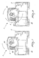
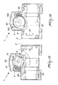
- the device further includes a locking microswitch 90 on which a locking lever 18 acts, the lever having a portion that is external to the containment body 2 and is provided with a hole 118 for the insertion of a padlock 218 or other device suitable to prevent the locking lever 18 from being moved from the open circuit breaker position shown in Figures 5 and 6.
- the locking lever 18 provides mechanical locking of the handle lever 20 by acting on an abutment 120 on the handle, as shown more clearly in Figure 6.
- Figures 3 and 4 show an intermediate position that the locking lever 18 can assume.
- the locking lever 18 deactivates the device only electrically, by pressing on the pushbutton of the microswitch 90, allowing to actuate the electrical device that is associated with the device without the device being activated.
- Figures 7 to 10 are views of the steps of the actuation of the circuit breaker and illustrate the relation between the position of the gear and the position of the handle.
- Figures 11 to 18 are views of the fundamental steps of the closure transition of the circuit breaker by virtue of the device.
- the preloaded spring 28 pushes the engagement pawl 13 onto an iron tooth 141 of the spring support 41 and the handle of the circuit breaker is in the 0° position, i.e., the open position.
- the preloaded spring 28 in the open position is shown in Figure 19.
- the engagement pawl 13 engages the release cam 8 and the handle of the circuit breaker moves through approximately 14°.
- the gear 40 continues to turn for another 110°, while the engagement pawl 13, rigidly coupled to the shaft 102, remains motionless, further loading the spring 28.
- the cam 140 rigidly coupled to the gear 40, moves the release cam 8, releasing the engagement pawl 13, which by being pushed by the spring 28 completes the stroke, driving the shaft 102.
- the handle of the circuit breaker moves from approximately 14° to approximately 84° in the closed circuit breaker position.
- the gear 40 completes the stroke through another 7° and makes the circuit breaker handle also cover another 6° of rotation, thus reaching 90°, and then resumes rotating in the opposite direction in order to return to the initial position.
- the spring 28 does not act, and the gear 40 pushes the circuit breaker directly without preventing its natural movement.
- Figures 24 and 25 are views of the self-powering system of the device, which is based on the driving wheel 39, the rotation of which is actuated by the shaft 102.
- the protrusion 117 of the self-powering lever 17 is inserted in a recess 139 so that the foot 217 of the lever 17 does not engage the pushbutton 61 of the self-powering microswitch 60.
- the protrusion 117 instead slides on the surface of the driving wheel 39 and forces the lever 17 to rotate toward the microswitch so that the foot 217 of the lever acts on the pushbutton 61.
- Figures 20 to 23 are views of the condition of the tripping microswitch 121 in relation to the four fundamental positions of the circuit breaker.
- the tripping microswitch 121 is open when the circuit breaker is in the open-tripped position; as shown in Figure 21, the tripping microswitch 121 is closed when the circuit breaker is in the open-armed position; as shown in Figure 22, the tripping microswitch 121 is closed when the circuit breaker is in the closed-armed position; and finally, as shown in Figure 23, the tripping microswitch 121 is open when the circuit breaker is in the closed-tripped position.
- the position of the handle that corresponds to the position in which the circuit breaker is open or closed determines the direction of rotation of the motor depending on the basis of the system shown in Figures 26-29, which is characterized by the presence of the handle position lever 22 that is provided with an elastic arc-like portion 122 that includes the stud 222 that acts in contrast with a fixed pivot 322 in order to produce a bistable condition of the position lever.
- Figures 26 and 28 illustrate the position of the handle and of the position lever 22 that corresponds to the open condition of the circuit breaker
- Figures 27 and 28 illustrate the position of the handle and of the position lever 22 that corresponds to the position in which the circuit breaker is closed.
- the action of the position lever 22 on the handle position microswitch 70 and on the rotation reversal microswitch 80 indicates to the device the position of the handle and the direction of rotation of the motor.
- an electrical remote actuation device having been provided that uses, by virtue of its particular kinematic structure, a low-power motor.
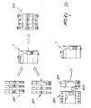
- the device according to the invention can be used with a complete range of electrical units, generally designated by the reference numeral 101, and accessories such as contacts, generally designated by the reference numeral 201.
- the device can also be associated with a unit that does not have the coupling for a triangular bar, such as a pure residual current-operated device, generally designated by the reference numeral 301, by means of a module 401 that is provided with an external actuation member 402 that is suitable to act on the handle of the residual current-operated device 301.
- a unit that does not have the coupling for a triangular bar such as a pure residual current-operated device, generally designated by the reference numeral 301, by means of a module 401 that is provided with an external actuation member 402 that is suitable to act on the handle of the residual current-operated device 301.
- the module 401 may also act as an automatic reset device in case of tripping following a fault of the circuit breaker with a selector of the number of authorized reclosings and adjustment of the maximum time within which the auxiliary device can perform the set reclosings.
- the materials used, as well as the dimensions, may of course be any according to requirements and to the state of the art.
Landscapes
- Breakers (AREA)
Applications Claiming Priority (2)
| Application Number | Priority Date | Filing Date | Title |
|---|---|---|---|
| ITMI20030991 | 2003-05-20 | ||
| ITMI20030991 ITMI20030991A1 (it) | 2003-05-20 | 2003-05-20 | Dispositivo di comando elettrico a distanza. |
Publications (2)
| Publication Number | Publication Date |
|---|---|
| EP1487002A2 true EP1487002A2 (de) | 2004-12-15 |
| EP1487002A3 EP1487002A3 (de) | 2005-01-12 |
Family
ID=33187381
Family Applications (1)
| Application Number | Title | Priority Date | Filing Date |
|---|---|---|---|
| EP04002046A Withdrawn EP1487002A3 (de) | 2003-05-20 | 2004-01-30 | Elektrische Fernbedienung |
Country Status (2)
| Country | Link |
|---|---|
| EP (1) | EP1487002A3 (de) |
| IT (1) | ITMI20030991A1 (de) |
Cited By (10)
| Publication number | Priority date | Publication date | Assignee | Title |
|---|---|---|---|---|
| EP1724804A3 (de) * | 2005-05-17 | 2008-03-05 | Bticino S.P.A. | Rückstellmodul für elektrische Schutzvorrichtung |
| EP1916691A3 (de) * | 2006-10-23 | 2009-06-24 | Gewiss S.P.A. | Vorrichtung zur automatischen Zurücksetzung und Selbstprüfung, insbesondere für durch Reststrom betriebene Leistungsschalter und Ähnliches |
| FR2940515A1 (fr) * | 2008-12-19 | 2010-06-25 | Schneider Electric Ind Sas | Dispositif de telecommande et disjoncteur telecommande equipe d'un tel dispositif |
| WO2010076403A1 (fr) | 2008-12-19 | 2010-07-08 | Schneider Electric Industries Sas | Dispositif de télécommande et disjoncteur télécommandé equipe d'un tel dispositif |
| WO2010099903A1 (de) * | 2009-03-04 | 2010-09-10 | Jozef Smrkolj | Mehrpoliger elektrischer selbstschalter |
| FR2959594A1 (fr) * | 2010-04-30 | 2011-11-04 | Schneider Electric Ind Sas | Dispositif de telecommande et disjoncteur telecommande equipe d'un tel dispositif. |
| CN103943429A (zh) * | 2014-04-04 | 2014-07-23 | 环宇集团有限公司 | 断路器的自动重合闸装置 |
| CN113066703A (zh) * | 2021-03-29 | 2021-07-02 | 广东电网有限责任公司 | 一种断路器的致动装置 |
| CN119092353A (zh) * | 2024-10-11 | 2024-12-06 | 中能苏创(浙江)自动化有限公司 | 一种防跳跃的柱上真空断路器 |
| EP4521438A1 (de) * | 2023-09-11 | 2025-03-12 | Schneider Electric (China) Co., Ltd. | Festkörperschutzschalter |
Families Citing this family (2)
| Publication number | Priority date | Publication date | Assignee | Title |
|---|---|---|---|---|
| CN107424885B (zh) * | 2017-06-29 | 2019-08-09 | 温州市正松电气有限公司 | 一种自动重合闸装置 |
| CN113972104B (zh) * | 2021-09-30 | 2023-07-28 | 环宇高科有限公司 | 一种小体积的模块化的自动分合闸物联网断路器 |
Family Cites Families (3)
| Publication number | Priority date | Publication date | Assignee | Title |
|---|---|---|---|---|
| FR2746209B1 (fr) * | 1996-03-18 | 1998-04-17 | Dispositif de telecommande pour un disjoncteur modulaire | |
| DE10013105C2 (de) * | 2000-03-17 | 2002-04-25 | Aeg Niederspannungstech Gmbh | Mikroschalter-Ansteuerung eines Fernantriebes für elektrische Schalteinrichtungen |
| US6448522B1 (en) * | 2001-01-30 | 2002-09-10 | General Electric Company | Compact high speed motor operator for a circuit breaker |
-
2003
- 2003-05-20 IT ITMI20030991 patent/ITMI20030991A1/it unknown
-
2004
- 2004-01-30 EP EP04002046A patent/EP1487002A3/de not_active Withdrawn
Cited By (15)
| Publication number | Priority date | Publication date | Assignee | Title |
|---|---|---|---|---|
| EP1724804A3 (de) * | 2005-05-17 | 2008-03-05 | Bticino S.P.A. | Rückstellmodul für elektrische Schutzvorrichtung |
| EP1916691A3 (de) * | 2006-10-23 | 2009-06-24 | Gewiss S.P.A. | Vorrichtung zur automatischen Zurücksetzung und Selbstprüfung, insbesondere für durch Reststrom betriebene Leistungsschalter und Ähnliches |
| CN101170027B (zh) * | 2006-10-23 | 2012-11-28 | 哥维斯股份公司 | 用于残余电流操作的断路器的自动复位及自检测装置 |
| CN102498538A (zh) * | 2008-12-19 | 2012-06-13 | 施耐德电器工业公司 | 远程控制装置和包括远程控制装置的远程控制断路器 |
| WO2010076403A1 (fr) | 2008-12-19 | 2010-07-08 | Schneider Electric Industries Sas | Dispositif de télécommande et disjoncteur télécommandé equipe d'un tel dispositif |
| FR2940515A1 (fr) * | 2008-12-19 | 2010-06-25 | Schneider Electric Ind Sas | Dispositif de telecommande et disjoncteur telecommande equipe d'un tel dispositif |
| CN102498538B (zh) * | 2008-12-19 | 2015-06-24 | 施耐德电器工业公司 | 远程控制装置和包括远程控制装置的远程控制断路器 |
| WO2010099903A1 (de) * | 2009-03-04 | 2010-09-10 | Jozef Smrkolj | Mehrpoliger elektrischer selbstschalter |
| FR2959594A1 (fr) * | 2010-04-30 | 2011-11-04 | Schneider Electric Ind Sas | Dispositif de telecommande et disjoncteur telecommande equipe d'un tel dispositif. |
| CN103943429A (zh) * | 2014-04-04 | 2014-07-23 | 环宇集团有限公司 | 断路器的自动重合闸装置 |
| CN103943429B (zh) * | 2014-04-04 | 2016-06-01 | 环宇集团浙江高科有限公司 | 断路器的自动重合闸装置 |
| CN113066703A (zh) * | 2021-03-29 | 2021-07-02 | 广东电网有限责任公司 | 一种断路器的致动装置 |
| EP4521438A1 (de) * | 2023-09-11 | 2025-03-12 | Schneider Electric (China) Co., Ltd. | Festkörperschutzschalter |
| US20250087436A1 (en) * | 2023-09-11 | 2025-03-13 | Schneider Electric (China) Co., Ltd. | Solid-state circuit breaker |
| CN119092353A (zh) * | 2024-10-11 | 2024-12-06 | 中能苏创(浙江)自动化有限公司 | 一种防跳跃的柱上真空断路器 |
Also Published As
| Publication number | Publication date |
|---|---|
| ITMI20030991A1 (it) | 2004-11-21 |
| EP1487002A3 (de) | 2005-01-12 |
Similar Documents
| Publication | Publication Date | Title |
|---|---|---|
| US6566618B2 (en) | Circuit breaker | |
| US5504290A (en) | Remote controlled circuit breaker with recharging cam | |
| US5838219A (en) | Electrical circuit breaker with manual and remote actuators | |
| EP2131376B1 (de) | Steuervorrichtung für Schutzschalter | |
| EP1487002A2 (de) | Elektrische Fernbedienung | |
| JPS62105333A (ja) | 電気回路遮断器の作動機構 | |
| AU2009202174B9 (en) | Control device of an electrical switchgear unit comprising a device for indicating welding of the contacts, and an electrical switchgear unit comprising one such device | |
| CN102842445A (zh) | 开关装置以及相关的电力分配系统 | |
| CN101154538B (zh) | 具有开关锁扣的开关装置 | |
| JP4127137B2 (ja) | 回路遮断器の外部操作ハンドル装置 | |
| CN118448224A (zh) | 一种塑壳断路器的磁通脱扣器复位结构 | |
| CN110085494B (zh) | 一种带防误合闸装置的断路器 | |
| CN102804321A (zh) | 用于带有摇臂的保护开关的开关单元 | |
| CN101617380B (zh) | 具有旋钮的开关装置 | |
| CN119446806A (zh) | 用于开关设备的双向操作机构及开关设备组件 | |
| JP4029664B2 (ja) | 回路しゃ断器 | |
| KR102621357B1 (ko) | 배전용차단기의 보조개폐장치 | |
| CN206774474U (zh) | 一种剩余电流脱扣机构及断路器 | |
| JP2009505344A (ja) | 開閉器の投入を防止するための嵌合式鎖錠機構 | |
| CN211828621U (zh) | 用于真空断路器的分闸机构、真空断路器和开关柜 | |
| CN109545630B (zh) | 一种断路器附件的操作机构、断路器附件及组合式断路器 | |
| KR100323738B1 (ko) | 기중차단기의 안전장치 | |
| JP3693129B2 (ja) | 回路遮断器の外部操作ハンドル装置 | |
| CN210608965U (zh) | 电动机起动器 | |
| EP1487003A1 (de) | Automatische Wiedereinschaltvorrichtung für die Fehlauslösung eines Schalters |
Legal Events
| Date | Code | Title | Description |
|---|---|---|---|
| PUAI | Public reference made under article 153(3) epc to a published international application that has entered the european phase |
Free format text: ORIGINAL CODE: 0009012 |
|
| PUAL | Search report despatched |
Free format text: ORIGINAL CODE: 0009013 |
|
| AK | Designated contracting states |
Kind code of ref document: A2 Designated state(s): AT BE BG CH CY CZ DE DK EE ES FI FR GB GR HU IE IT LI LU MC NL PT RO SE SI SK TR |
|
| AX | Request for extension of the european patent |
Extension state: AL LT LV MK |
|
| AK | Designated contracting states |
Kind code of ref document: A3 Designated state(s): AT BE BG CH CY CZ DE DK EE ES FI FR GB GR HU IE IT LI LU MC NL PT RO SE SI SK TR |
|
| AX | Request for extension of the european patent |
Extension state: AL LT LV MK |
|
| AKX | Designation fees paid | ||
| REG | Reference to a national code |
Ref country code: DE Ref legal event code: 8566 |
|
| STAA | Information on the status of an ep patent application or granted ep patent |
Free format text: STATUS: THE APPLICATION IS DEEMED TO BE WITHDRAWN |
|
| 18D | Application deemed to be withdrawn |
Effective date: 20050713 |