EP1487064A1 - Abdichtungsanordnung für elektrische Anschlusselemente - Google Patents
Abdichtungsanordnung für elektrische Anschlusselemente Download PDFInfo
- Publication number
- EP1487064A1 EP1487064A1 EP04012666A EP04012666A EP1487064A1 EP 1487064 A1 EP1487064 A1 EP 1487064A1 EP 04012666 A EP04012666 A EP 04012666A EP 04012666 A EP04012666 A EP 04012666A EP 1487064 A1 EP1487064 A1 EP 1487064A1
- Authority
- EP
- European Patent Office
- Prior art keywords
- housing parts
- sealing device
- web
- contact element
- folded
- Prior art date
- Legal status (The legal status is an assumption and is not a legal conclusion. Google has not performed a legal analysis and makes no representation as to the accuracy of the status listed.)
- Withdrawn
Links
Images
Classifications
-
- H—ELECTRICITY
- H01—ELECTRIC ELEMENTS
- H01R—ELECTRICALLY-CONDUCTIVE CONNECTIONS; STRUCTURAL ASSOCIATIONS OF A PLURALITY OF MUTUALLY-INSULATED ELECTRICAL CONNECTING ELEMENTS; COUPLING DEVICES; CURRENT COLLECTORS
- H01R13/00—Details of coupling devices of the kinds covered by groups H01R12/70 or H01R24/00 - H01R33/00
- H01R13/46—Bases; Cases
- H01R13/52—Dustproof, splashproof, drip-proof, waterproof, or flameproof cases
- H01R13/5216—Dustproof, splashproof, drip-proof, waterproof, or flameproof cases characterised by the sealing material, e.g. gels or resins
-
- H—ELECTRICITY
- H01—ELECTRIC ELEMENTS
- H01R—ELECTRICALLY-CONDUCTIVE CONNECTIONS; STRUCTURAL ASSOCIATIONS OF A PLURALITY OF MUTUALLY-INSULATED ELECTRICAL CONNECTING ELEMENTS; COUPLING DEVICES; CURRENT COLLECTORS
- H01R13/00—Details of coupling devices of the kinds covered by groups H01R12/70 or H01R24/00 - H01R33/00
- H01R13/46—Bases; Cases
- H01R13/52—Dustproof, splashproof, drip-proof, waterproof, or flameproof cases
- H01R13/521—Sealing between contact members and housing, e.g. sealing insert
-
- H—ELECTRICITY
- H01—ELECTRIC ELEMENTS
- H01R—ELECTRICALLY-CONDUCTIVE CONNECTIONS; STRUCTURAL ASSOCIATIONS OF A PLURALITY OF MUTUALLY-INSULATED ELECTRICAL CONNECTING ELEMENTS; COUPLING DEVICES; CURRENT COLLECTORS
- H01R12/00—Structural associations of a plurality of mutually-insulated electrical connecting elements, specially adapted for printed circuits, e.g. printed circuit boards [PCB], flat or ribbon cables, or like generally planar structures, e.g. terminal strips, terminal blocks; Coupling devices specially adapted for printed circuits, flat or ribbon cables, or like generally planar structures; Terminals specially adapted for contact with, or insertion into, printed circuits, flat or ribbon cables, or like generally planar structures
- H01R12/50—Fixed connections
- H01R12/59—Fixed connections for flexible printed circuits, flat or ribbon cables or like structures
- H01R12/592—Fixed connections for flexible printed circuits, flat or ribbon cables or like structures connections to contact elements
Definitions
- the invention relates to a sealing device for an electrical terminal on a flexible cable disposed in a connector housing.
- 'FFC-foil' flexible flat cable
- a connector is provided at an end of the cable, with contacts attached to terminals formed at the ends of the conductors.
- the connector comprises a housing with two housing parts, pivotally connected to one another at one end of the connector via a pivoting connection with the housing parts opposing one another like a clamshell. In certain applications, such as automotive electrical systems, it is important to seal the connector against water to protect the electrical terminals disposed between the contacts and conductors.
- Existing connector housings are provided with circular seals such as annular face seals.
- the two housing parts are brought together and folded against one another on the FFC-foil, which is arranged between the housing parts. In the folded position the annular face seals are fixed so that the terminals are surrounded by the circular seals of the two housing parts and the space enclosed by the housing parts is sealed against water.
- the housing further comprises a receptacle, sealed against the two housing parts, and into which the contact elements can be inserted.
- a plug connection between the contact elements of the connector and complementary contact elements of a mating connector can be created via a plug provided with the complementary contact elements, which can be inserted into the receptacle.
- sealing devices In the known sealing devices, however, the creation of an effective seal of the terminals against water requires a relatively high contact pressure of the seals on the cable, requiring considerable force when folding the housing parts.
- the sealing devices therefore typically have screw connections to facilitate the folding of the housing parts, whereby the construction of a sealing device becomes complicated and attaching the sealing device to a carrier becomes awkward.
- the need for a screw connection is a particular disadvantage where space is limited at the assembly position of the sealing device.
- the object of the present invention is to provide an improved sealing device which has a simple construction and facilitates a secure seal of a terminal of a conductor carried on a flexible cable with quick and easy handling.
- the sealing device for an electrical terminal 24 of a conductor carried in a carrier 21 which is electrically connected to a contact element 22 via the terminal 24.
- the sealing device comprises a housing having two housing parts 2, the two housing parts 2 being foldable at one end via a pivoting connection 4 to seal the terminal 24.
- the two housing parts 2 are respectively constructed as plate-shaped covers with large-area seals 3 on the inner faces of the covers.
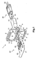
- FIG. 1 shows a perspective view of a plug connector 30, a sealing device 1 according to an embodiment of the invention and a conductor carrier in the form of a flat foil cable 20.
- the flat foil cable 20 comprises a foil 21 within which a plurality of flat conductors (not shown in the figures) are arranged.
- the foil 21 acts as a carrier which also seals the conductors against water.
- the flat foil cable 20 has four terminals 24, by which two conductors are electrically connected to contact elements constructed as contact pins 22, and two further conductors are electrically connected to a diode 23.
- the terminals 24 shown in Fig. 1 are constructed as crimp connections which form an electrical connection with the conductors of the flat foil cable 20, with the aid of crimp sleeves which penetrate the foil 21 and enclose the conductors.
- the conductors of the flat foil cable 20 can also be contacted via differently constructed terminals, such as for example piercing connections.
- the sealing device 1 securely seals the terminals 24 of the flat foil cable 20 against water.
- the sealing device 1 comprises a housing with two housing parts 2, which are foldably connected to one another at one end via a pivoting connection 4.
- the two housing parts 2 are constructed respectively as plate-shaped covers with large-area seals 3 on the inner faces of the covers.
- the large-area seals are formed by self-adhesive gel cushions 3.
- the housing parts 2 are brought together on the flat foil cable 20 arranged between the housing parts 2 in the region of the terminals 24, the self-adhesive gel cushions adhere to each other and to the flat foil cable 20 to provide a watertight seal of the space enclosed by the housing parts 2 and thus the terminals 24.
- folding the housing parts 2 only requires a small force as the gel cushions 3 consist of a very flexible, formable and flowable material.
- the width of the housing parts 2 of the sealing device 1 is greater than the width of the foil 21.
- the side walls 11 are provided with corresponding latching lugs 12 and recesses 13 to engage the folded housing parts 2 with one another.
- the housing parts 2 are durably affixed to one another, and thus, a reliable seal of the terminals 24 is achieved.
- One of the two housing parts 2 additionally comprises two pins 15 on the inner face which engage in recesses 25 on the sides of the foil 21 when the housing parts 2 are folded to fix the sealing device 1 onto the flat foil cable 20.
- a strain relief device is produced so that when a pulling force acts on the sealing device 1 no tensile force is exerted on the terminals 24 but is absorbed by the foil 21 via the recesses 25.
- the pivoting connection 4 of the sealing device 1 comprises a web 5 with a plurality of apertures 6, allowing the pivoting connection 4 to be pushed onto the contact pins 22 and the diode 23 on the flat foil cable 20.
- the two housing parts 2 are pivotally hinged on the web 5 via natural hinges 10.
- the web 5 is of substantially U-shaped construction in cross-section with a receiving aperture 7 comprising two recesses 8.
- a receiving aperture 7 comprising two recesses 8.
- the housing of the sealing device 1 Adjacent to the web 5, the housing of the sealing device 1 comprises a receptacle 14 into which the contact pins 22 are inserted before the housing parts 2 are folded. With the aid of latching elements not shown in the figures, the contact pins 22 are thus engaged with the receptacle 14.
- the receptacle 14 is further configured to receive the mating plug connector 30 which is provided with complementary contact bushings 31. In this manner the sealing device 1 acts as a socket connector into which the plug connector 30 is inserted to create electrical connections between the complementary contact pins 22 and contact bushings 31. As Fig. 1 shows the contact bushings 31 are further connected to conductors in cables 32.
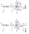
- the following figures 2 to 4 illustrate the process of attaching the sealing device 1 to the flat foil conductor 20.
- the substantially U-shaped cross-section of the web 5 of the pivoting connection 4 is clearly visible.
- the flat foil cable 20 is inserted between the housing parts 2 which are in an open position (i.e., not pivoted together).
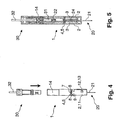
- the sealing device 1 is then positioned on the flat foil cable 20 in such a manner that the contact pins 22 are inserted through the web 5 into the receptacle 14. Subsequently the housing parts 2 are folded as indicated by the arrows in Fig. 3, so that the side walls 11 of the housing parts 2 engage with one another in the form of a box, as shown in Fig. 4. In addition to the encapsulation of the terminals 24 of the flat foil cable 20 thereby produced, a compact space-saving geometry of the sealing device 1 simultaneously results. With reference to Fig. 4, it is further clearly visible that the curved hooks 9 of the side walls 11 engage in the recesses 8 of the receiving aperture 7 of the web 5 and thereby engage the folded housing parts 2 with the web 5.
- Fig. 5 shows a side sectional view of the sealing device 1 attached to the flat foil cable 20 with the mating plug connector 30 inserted into the receptacle 14.
- the self-adhesive gel cushions 3 seal the space enclosed by the housing parts 2 and thus the terminals 24.
- the terminals 24 are thus also sealed against the receptacle 14 of the sealing device 1.
- the gel cushions 3 may be partially pressed into the receptacle 14 when the housing parts 2 are folded. This is achieved, for example, by the inner faces of the covers of the housing parts 2 being provided with a chamfer not shown in Fig. 5.
- the sealing device 1 shown in the figures comprises self-adhesive gel cushions 3 as large-area seals.
- Gel cushions are used which are provided with a non-adhesive coating on the surfaces facing the flat foil conductor.
- increased contact pressure of the gel cushions on the flat foil conductor requires application of a greater force when the housing parts are folded to achieve a correspondingly secure seal, as the coating slightly reduces the yielding of the gel cushions.
- Higher contact pressure could be produced, for example, with the aid of additional ribs on the inner faces of the covers of the housing parts, exerting additional compression force of the gel cushions.
- coated gel cushions has the advantage, however, that these gel cushions, in contrast to the non-coated gel cushions, do not have to be protected against dust and dirt by costly packaging when the sealing device is transported. Similarly, this accordingly applies to the use of other large-area, flexible seals which do not consist of gel.
- sealing device is not restricted to sealing terminals of a flat foil cable.
- Embodiments are contemplated which are configured to seal terminals of, for example, printed circuit boards or other carriers provided with conductors.
Landscapes
- Chemical & Material Sciences (AREA)
- Dispersion Chemistry (AREA)
- Connector Housings Or Holding Contact Members (AREA)
Applications Claiming Priority (2)
| Application Number | Priority Date | Filing Date | Title |
|---|---|---|---|
| DE10326318 | 2003-06-11 | ||
| DE10326318A DE10326318B3 (de) | 2003-06-11 | 2003-06-11 | Abdichtungsvorrichtung für eine elektrische Anschlussstelle |
Publications (1)
| Publication Number | Publication Date |
|---|---|
| EP1487064A1 true EP1487064A1 (de) | 2004-12-15 |
Family
ID=33185744
Family Applications (1)
| Application Number | Title | Priority Date | Filing Date |
|---|---|---|---|
| EP04012666A Withdrawn EP1487064A1 (de) | 2003-06-11 | 2004-05-28 | Abdichtungsanordnung für elektrische Anschlusselemente |
Country Status (4)
| Country | Link |
|---|---|
| US (1) | US20050020131A1 (de) |
| EP (1) | EP1487064A1 (de) |
| JP (1) | JP2005005269A (de) |
| DE (1) | DE10326318B3 (de) |
Cited By (3)
| Publication number | Priority date | Publication date | Assignee | Title |
|---|---|---|---|---|
| EP1729369A3 (de) * | 2005-06-03 | 2007-11-21 | Tyco Electronics AMP GmbH | Kontaktvorrichtung zum kontaktieren von Leiterfolien |
| EP2144336A1 (de) * | 2008-06-30 | 2010-01-13 | INARCA S.p.A. | Luftdichter zweipoliger oder mehrpoliger Stecker |
| WO2010082967A1 (en) * | 2009-01-14 | 2010-07-22 | Molex Incorporated | Weather-resistant cable connector, electrical modules and weather-resistant assemblies thereof |
Families Citing this family (9)
| Publication number | Priority date | Publication date | Assignee | Title |
|---|---|---|---|---|
| DE20319011U1 (de) * | 2003-12-05 | 2005-04-21 | Molex Incorporated, Lisle | Flachleiterverbinder für abgedichtete Anwendungen |
| JP2006302850A (ja) | 2005-04-25 | 2006-11-02 | Yazaki Corp | 防水パッキンとそれを用いた防水コネクタ及びその製造方法 |
| DE102005030554A1 (de) * | 2005-06-22 | 2006-12-28 | Lapp Engineering & Co. | Steckverbinderelement |
| JP4726002B2 (ja) * | 2005-08-31 | 2011-07-20 | 株式会社アイペックス | コネクタ装置 |
| DE202005018318U1 (de) * | 2005-10-28 | 2007-03-15 | Weidmüller Interface GmbH & Co. KG | Steckverbindung für Flachkabel und Kontaktelement für eine derartige Steckverbindung |
| US8113880B2 (en) * | 2006-05-12 | 2012-02-14 | Fci Automotive Holding | Electrical connector |
| DE112012002847B4 (de) * | 2011-07-04 | 2024-06-20 | Yazaki Corporation | Flachkabel-Wasserabdichtungssteckverbinder und Wasserabdichtungssteckverbinderaufbau für Flachkabel |
| JP7438907B2 (ja) * | 2020-09-23 | 2024-02-27 | 東芝テック株式会社 | 電装品 |
| US11652313B2 (en) | 2021-08-17 | 2023-05-16 | Lear Corporation | Split cover electrical connector for flat cable |
Citations (3)
| Publication number | Priority date | Publication date | Assignee | Title |
|---|---|---|---|---|
| US5356308A (en) * | 1991-10-31 | 1994-10-18 | Sumitomo Wiring Systems, Ltd. | Connector assembly for a flexible wiring plate |
| US5828005A (en) * | 1995-11-01 | 1998-10-27 | Raychem Corporation | Gel-filled closure |
| DE19958968A1 (de) * | 1999-12-07 | 2001-06-28 | Siemens Ag | Leitungsabschlußmodul |
Family Cites Families (6)
| Publication number | Priority date | Publication date | Assignee | Title |
|---|---|---|---|---|
| US3090028A (en) * | 1960-03-28 | 1963-05-14 | Bendix Corp | Electrical connector |
| US3879099A (en) * | 1973-09-04 | 1975-04-22 | Amp Inc | Flat fexible cable connector assembly including insulation piercing contacts |
| FR2740916B1 (fr) * | 1995-11-02 | 1997-12-05 | Sylea | Perfectionnements aux dispositifs de shuntage de plusieurs organes de contacts electriques |
| JP2000082527A (ja) * | 1998-09-08 | 2000-03-21 | Yazaki Corp | 防水コネクタ |
| JP4138315B2 (ja) * | 1999-09-20 | 2008-08-27 | ヴェルツ・アーゲー | 平形ケーブル用接点デバイス |
| JP3696455B2 (ja) * | 1999-10-08 | 2005-09-21 | 矢崎総業株式会社 | 防水コネクタ |
-
2003
- 2003-06-11 DE DE10326318A patent/DE10326318B3/de not_active Expired - Fee Related
-
2004
- 2004-05-28 EP EP04012666A patent/EP1487064A1/de not_active Withdrawn
- 2004-06-08 US US10/863,614 patent/US20050020131A1/en not_active Abandoned
- 2004-06-10 JP JP2004172899A patent/JP2005005269A/ja active Pending
Patent Citations (3)
| Publication number | Priority date | Publication date | Assignee | Title |
|---|---|---|---|---|
| US5356308A (en) * | 1991-10-31 | 1994-10-18 | Sumitomo Wiring Systems, Ltd. | Connector assembly for a flexible wiring plate |
| US5828005A (en) * | 1995-11-01 | 1998-10-27 | Raychem Corporation | Gel-filled closure |
| DE19958968A1 (de) * | 1999-12-07 | 2001-06-28 | Siemens Ag | Leitungsabschlußmodul |
Cited By (8)
| Publication number | Priority date | Publication date | Assignee | Title |
|---|---|---|---|---|
| EP1729369A3 (de) * | 2005-06-03 | 2007-11-21 | Tyco Electronics AMP GmbH | Kontaktvorrichtung zum kontaktieren von Leiterfolien |
| US7444743B2 (en) | 2005-06-03 | 2008-11-04 | Tyco Electronics Amp Gmbh | Connecting device for connecting electrical foil conductors |
| CN1881721B (zh) * | 2005-06-03 | 2010-04-21 | 泰科电子Amp有限责任公司 | 用于连接电箔导体的连接装置 |
| EP2144336A1 (de) * | 2008-06-30 | 2010-01-13 | INARCA S.p.A. | Luftdichter zweipoliger oder mehrpoliger Stecker |
| WO2010082967A1 (en) * | 2009-01-14 | 2010-07-22 | Molex Incorporated | Weather-resistant cable connector, electrical modules and weather-resistant assemblies thereof |
| CN102349197A (zh) * | 2009-01-14 | 2012-02-08 | 莫列斯公司 | 耐候性电缆连接器、电气模块及其耐候性组件 |
| US8764475B2 (en) | 2009-01-14 | 2014-07-01 | Molex Incorporated | Weather-resistant cable connector, electrical modules and weather-resistant assemblies thereof |
| CN102349197B (zh) * | 2009-01-14 | 2014-09-03 | 莫列斯公司 | 耐候性电缆连接器、电气模块及其耐候性组件 |
Also Published As
| Publication number | Publication date |
|---|---|
| JP2005005269A (ja) | 2005-01-06 |
| DE10326318B3 (de) | 2005-03-03 |
| US20050020131A1 (en) | 2005-01-27 |
Similar Documents
| Publication | Publication Date | Title |
|---|---|---|
| US8096828B2 (en) | Electrical connector for terminating a coaxial cable | |
| US5890922A (en) | Electrical connector | |
| US4948378A (en) | Waterproof electrical connector assembly | |
| US20050020131A1 (en) | Sealing device for an electrical terminal | |
| KR920017303A (ko) | 무 페루울형 백 셸 | |
| US7727020B2 (en) | Cable connector | |
| US6116931A (en) | Contact array for electrical interface connector | |
| CN1212081A (zh) | 多极电插接件和配属的插座部分 | |
| JP2009187769A (ja) | コネクタ | |
| JP3028988B2 (ja) | コネクタ | |
| US20140154916A1 (en) | Waterproof connector | |
| US7258553B2 (en) | Sealed electrical connector assembly | |
| EP3113293A1 (de) | Peripheres keildichtungselement | |
| KR102463691B1 (ko) | 커넥터 | |
| CN115810949A (zh) | 电连接器 | |
| EP1012920B1 (de) | Kabelverbinder | |
| US20090181567A1 (en) | Sealed connector | |
| JPH11176499A (ja) | プリント回路基板と平型柔軟ケーブルの接続用 電気コネクタ | |
| JP2003059552A (ja) | プラグコネクタ | |
| KR960009273A (ko) | 내부에 전기부품을 갖는 전기 컨넥터를 구비한 전기 하니스 및 그 제조방법 | |
| KR19990044258A (ko) | 특성상 스냅을 갖는 접점 블록 | |
| US20240364064A1 (en) | Single-pair ethernet connector jack | |
| US11527850B1 (en) | Connector backshell assembly | |
| WO2023028369A1 (en) | Single-pair ethernet connector jack | |
| JP4387167B2 (ja) | 圧接コネクタ |
Legal Events
| Date | Code | Title | Description |
|---|---|---|---|
| PUAI | Public reference made under article 153(3) epc to a published international application that has entered the european phase |
Free format text: ORIGINAL CODE: 0009012 |
|
| AK | Designated contracting states |
Kind code of ref document: A1 Designated state(s): AT BE BG CH CY CZ DE DK EE ES FI FR GB GR HU IE IT LI LU MC NL PL PT RO SE SI SK TR |
|
| AX | Request for extension of the european patent |
Extension state: AL HR LT LV MK |
|
| AKX | Designation fees paid | ||
| REG | Reference to a national code |
Ref country code: DE Ref legal event code: 8566 |
|
| STAA | Information on the status of an ep patent application or granted ep patent |
Free format text: STATUS: THE APPLICATION IS DEEMED TO BE WITHDRAWN |
|
| 18D | Application deemed to be withdrawn |
Effective date: 20050616 |