EP1487558B1 - Längeneinstellbare filterpatronenendkappen, diese verwendende filterpatronen und verfahren zu ihrer herstellung - Google Patents
Längeneinstellbare filterpatronenendkappen, diese verwendende filterpatronen und verfahren zu ihrer herstellung Download PDFInfo
- Publication number
- EP1487558B1 EP1487558B1 EP03745561A EP03745561A EP1487558B1 EP 1487558 B1 EP1487558 B1 EP 1487558B1 EP 03745561 A EP03745561 A EP 03745561A EP 03745561 A EP03745561 A EP 03745561A EP 1487558 B1 EP1487558 B1 EP 1487558B1
- Authority
- EP
- European Patent Office
- Prior art keywords
- annular
- lip seal
- connection
- spacer ring
- flange
- Prior art date
- Legal status (The legal status is an assumption and is not a legal conclusion. Google has not performed a legal analysis and makes no representation as to the accuracy of the status listed.)
- Expired - Lifetime
Links
- 238000000034 method Methods 0.000 title claims description 9
- 125000006850 spacer group Chemical group 0.000 claims abstract description 28
- 238000007789 sealing Methods 0.000 claims abstract description 6
- 238000001914 filtration Methods 0.000 claims description 13
- 239000012530 fluid Substances 0.000 claims description 11
- 238000010438 heat treatment Methods 0.000 claims description 6
- 238000001816 cooling Methods 0.000 claims description 2
- 238000004519 manufacturing process Methods 0.000 description 3
- -1 polypropylene Polymers 0.000 description 2
- 239000004698 Polyethylene Substances 0.000 description 1
- 239000004743 Polypropylene Substances 0.000 description 1
- 210000005069 ears Anatomy 0.000 description 1
- 239000000835 fiber Substances 0.000 description 1
- 238000003780 insertion Methods 0.000 description 1
- 230000037431 insertion Effects 0.000 description 1
- 238000009434 installation Methods 0.000 description 1
- 238000005304 joining Methods 0.000 description 1
- 239000000463 material Substances 0.000 description 1
- 238000012986 modification Methods 0.000 description 1
- 230000004048 modification Effects 0.000 description 1
- 229920000573 polyethylene Polymers 0.000 description 1
- 229920000098 polyolefin Polymers 0.000 description 1
- 229920001155 polypropylene Polymers 0.000 description 1
- 229920001169 thermoplastic Polymers 0.000 description 1
- 238000003466 welding Methods 0.000 description 1
Images


Classifications
-
- B—PERFORMING OPERATIONS; TRANSPORTING
- B01—PHYSICAL OR CHEMICAL PROCESSES OR APPARATUS IN GENERAL
- B01D—SEPARATION
- B01D29/00—Filters with filtering elements stationary during filtration, e.g. pressure or suction filters, not covered by groups B01D24/00 - B01D27/00; Filtering elements therefor
- B01D29/11—Filters with filtering elements stationary during filtration, e.g. pressure or suction filters, not covered by groups B01D24/00 - B01D27/00; Filtering elements therefor with bag, cage, hose, tube, sleeve or like filtering elements
- B01D29/114—Filters with filtering elements stationary during filtration, e.g. pressure or suction filters, not covered by groups B01D24/00 - B01D27/00; Filtering elements therefor with bag, cage, hose, tube, sleeve or like filtering elements arranged for inward flow filtration
-
- B—PERFORMING OPERATIONS; TRANSPORTING
- B01—PHYSICAL OR CHEMICAL PROCESSES OR APPARATUS IN GENERAL
- B01D—SEPARATION
- B01D29/00—Filters with filtering elements stationary during filtration, e.g. pressure or suction filters, not covered by groups B01D24/00 - B01D27/00; Filtering elements therefor
- B01D29/11—Filters with filtering elements stationary during filtration, e.g. pressure or suction filters, not covered by groups B01D24/00 - B01D27/00; Filtering elements therefor with bag, cage, hose, tube, sleeve or like filtering elements
- B01D29/13—Supported filter elements
- B01D29/15—Supported filter elements arranged for inward flow filtration
- B01D29/21—Supported filter elements arranged for inward flow filtration with corrugated, folded or wound sheets
-
- B—PERFORMING OPERATIONS; TRANSPORTING
- B01—PHYSICAL OR CHEMICAL PROCESSES OR APPARATUS IN GENERAL
- B01D—SEPARATION
- B01D29/00—Filters with filtering elements stationary during filtration, e.g. pressure or suction filters, not covered by groups B01D24/00 - B01D27/00; Filtering elements therefor
- B01D29/96—Filters with filtering elements stationary during filtration, e.g. pressure or suction filters, not covered by groups B01D24/00 - B01D27/00; Filtering elements therefor in which the filtering elements are moved between filtering operations; Particular measures for removing or replacing the filtering elements; Transport systems for filters
-
- B—PERFORMING OPERATIONS; TRANSPORTING
- B01—PHYSICAL OR CHEMICAL PROCESSES OR APPARATUS IN GENERAL
- B01D—SEPARATION
- B01D2201/00—Details relating to filtering apparatus
- B01D2201/24—Tools used for the removal of filters
-
- B—PERFORMING OPERATIONS; TRANSPORTING
- B01—PHYSICAL OR CHEMICAL PROCESSES OR APPARATUS IN GENERAL
- B01D—SEPARATION
- B01D2201/00—Details relating to filtering apparatus
- B01D2201/29—Filter cartridge constructions
- B01D2201/291—End caps
- B01D2201/295—End caps with projections extending in a radial outward direction, e.g. for use as a guide, spacing means
-
- B—PERFORMING OPERATIONS; TRANSPORTING
- B01—PHYSICAL OR CHEMICAL PROCESSES OR APPARATUS IN GENERAL
- B01D—SEPARATION
- B01D2201/00—Details relating to filtering apparatus
- B01D2201/34—Seals or gaskets for filtering elements
Definitions
- the present invention relates generally to the field of filter cartridges. More particularly, the present invention relates to length-adjustable filter cartridge end-caps and to filter cartridges which include such length-adjustable end caps.
- novel length-adjustable filter cartridges having at least one length-adjustable end cap attached to an end of the filter body.
- the length-adjustable end cap most preferably includes an annular stationary ring member which is attached to one end of the filter body, and a moveable connection member slideably received within the annular stationary ring member so as to be moveable longitudinally relative thereto.
- length-adjustable end caps and filter cartridges including the same are provided.
- a length adjustable end cap as defined in claim 8.
- the lip seal is a segment of a conical surface and thereby has a proximal edge region which is unitarily joined to the ring member and an opposite distal terminal end which projects downwardly and inwardly into the opening defined by the ring member.
- a filter cartridge as defined in claim 1.
- FIGURE 1 depicts a particularly preferred filter cartridge 10 in accordance with the present invention.
- the filter cartridge 10 includes a generally cylindrical filter body 12 which is closed at one end by a bottom end cap 14.
- a length-adjustable end-cap 16 is joined to the upper end of the filter body 12.
- the filter body 12 may be formed of virtually any filtration media conventionally employed to filter fluids.
- the filtration media may be comprised of pleated sheets of non-woven or woven filter materials which are, in and of themselves, highly conventional in the fluid filtration art.
- the filter body 12 is comprised of a generally cylindrical, non-woven mass of melt-blown polymeric fibers formed, for example, from thermoplastic polymers, preferably polyolefins such as polypropylene, polyethylene and the like.
- Especially preferred filter media for use as the filter body 12 in accordance with the present invention are those as described more fully in commonly owned U.S. Patent Nos. 5,591,335 and 6,342,283 .
- the length-adjustable end cap 16 includes an annular stationary ring member 22 having an annular connection flange 22-1 which is physically attached to the end surface of the filter body 12 most preferably by thermal bonding (i.e., heat welding) in a manner to be described below.
- a moveable connection member 26 includes a lower cylindrical neck portion 28 and an upper annular flange portion 30.
- the flange portion 30 will typically be provided with an elastomeric edge seal 30-1 so as to provide a fluid seal between the flange 30 and adjacent structural components of a housing (not shown) in which the filter cartridge 10 is employed.
- the neck and flange portions 28, 30 are formed as a unitary (one-piece) structure and provided with a cross-support 31 so as to increase the structural integrity of the same while yet providing a convenient fixed handle to allow removal/insertion of the connection member 28 relative to the circular interior opening 22a defined by the stationary ring member 22 (see FIGURE 2 ).
- connection member 26 is slideable along the longitudinal axis of the filter cartridge 10 so that the flange portion 30 thereof may be moved towards and away from the stationary ring member 22.
- annular inwardly projecting flexible lip seal 32 which is formed as a unitary (one piece) structure with the stationary ring member 22.
- An annular spacer ring 34 is coaxially positioned in spaced relationship below the lip seal 32 and is seated in a partly conformingly shaped recess 36 (see FIGURE 2 ) formed in a lower region of the connection flange 22-1 of the stationary ring member 22.
- the spacer flange 34 serves to protect the lip seal 32 during the thermal bonding operation and also serves to ensure that a relatively snug, but sliding, fit is established with the exterior circumferential surface of cylindrical neck portion 28 of the moveable connection member 26.
- the lip seal 32 may be formed of virtually any desired geometric configuration which projects inwardly, and preferably downwardly, so as to constrict the opening 22a in which the neck portion 28 is inserted.
- the lip seal 32 must, of course, be capable of being yieldably outwardly flexed somewhat when in contact with the outer surface of the neck portion 28 so as to thereby maintain sealing contact therewith. Fluid pressure will also serve to urge the lip seal 32 into sealing contact with the neck portion 28 due to the interior of the filter medium 12 being at a greater fluid pressure as compared to the fluid pressure on the exterior of the filter medium 12 (e.g., due to the inside-out flow of the fluid being filtered and the filter drop across the radial thickness dimension of the filter medium).
- the lip seal 32 is in the form of a generally conical segment oriented in an inward and downward direction (i.e., in a slanted direction from the ring member 22 toward the bottom end cap 14).
- the terminal (lower) end of the neck portion 28 is provided with an exterior circumferential bevel 28-1 which assists in the positioning of the neck portion 28 within the stationary ring member. That is, the circumferential bevel 28-1 provides a pilot surface to allow the neck portion to be properly positioned with respect to the annular lip seal 32 so that the neck portion may be inserted within the stationary ring member 22.
- the moveable connection member 26 be capable of being physically removed from the stationary ring member 22.
- the cross-support 31 provides a convenient handle to allow the connection member 26 to be withdrawn from the ring member 22 while the latter remains associated with its supporting structure (for example, a filter housing).
- the stationary ring 22 also be provided with a diametrically opposed pair of bail ears 22-2 which pivotally accept the terminal ends of a semi-circular bail 22-3.
- the remaining structural portions of the filter cartridge 10 may be removed physically from its adjacent supporting structure (e.g., a filter housing, not shown) by manually lifting it with the aid of the bail 22-3.
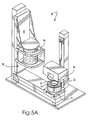
- FIGURES 5A-5D depict a preferred system 50 and technique whereby end caps may be thermally bonded to a cylindrical filter body 12.
- the system includes a carriage 52 on which provides a platform to support a nest 54 holding a stationary ring member 22 in an inverted manner.
- the bottom surface of the ring member 22 and the spacer ring 34 are exposed to the heating station 56.
- a generally cylindrical heat shield puck 57 is positioned removably within the interior of the end cap.
- the heat shield puck 57 serves to protect the unitary lip seal of the ring member 22 during the thermal bonding operation.
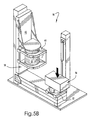
- the carriage 52 is capable of reciprocal rectilinear movements between the heating station 56 and the bonding station 58 so as to shuttle the nest 54 and the inverted ring member 22 therebetween.
- the heating station is moveable into thermal contact with the nest 54 and the inverted ring member 22 held therein so as to melt a portion of the connection flange 22-1 which is exposed to the heating station 56.
- the exposed portion of the spacer ring 34 is also concurrently melted at this time.
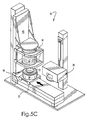
- the heating station 56 is raised and the carriage 52 is shuttled to the bonding station 58 so as to be in coaxial alignment with the filter body 12 held in support structure 60.
- FIGURE 5C Such a state is shown in FIGURE 5C . It will be observed in this regard that the spacer ring 34 has thermally melded with an adjacent surrounding portion of the flange 22-1.
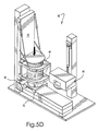
- the filter body 12 is then brought into contact with the melted region of the flange 22-1 by lowering of the support structure 60 along vertical support post 62 as shown in FIGURE 5D .
- the filter body 12 and the connection flange 22-1 are thermally melded so as to form an integral structure.
- the end of the filter body 12 is embedded physically within, and melded to, the flange 22-1 to a thickness dimension D (see FIGURE 4 ) of at least about 2.54mm (0.100 inch), and more preferably between about 2.54mm to about 3.18mm (about 0.100 to about 0.125 inch).
- an integral fluid-tight bond is established between the end of the filter body 12 and the flange 22-1 associated with the stationary retaining ring 22.
- the bottom end cap 14 may be thermally bonded to the other end of the filter body 12 in a similar fashion to that described above with reference to FIGURES 5A-5D .
Landscapes
- Chemical & Material Sciences (AREA)
- Chemical Kinetics & Catalysis (AREA)
- Filtering Of Dispersed Particles In Gases (AREA)
- Filtration Of Liquid (AREA)
Claims (14)
- Filterpatrone, umfassend:einen im Wesentlichen zylindrischen, ringförmigen Filterkörper (12) mit einem Inneren und einem Fluidfiltrationsmedium, undeine längeneinstellbare Endkappe (16), welche mit einem Ende des Filterkörpers (12) verbunden ist; dadurch gekennzeichnet, dass die Endkappe (16) ein stationäres Ringelement (22) und ein Verbindungselement (26) umfasst;wobei das stationäre Ringelement (22) aufweist: eine mit dem Inneren des Filterkörpers (12) kommunizierende Öffnung (22a); eine ringförmige Lippendichtung (32), welche einstückig mit dem stationären Ringelement ausgebildet ist; einen ringförmigen Verbindungsflansch (22-1), der mit dem Ende des Filterkörpers (12) verbunden ist und eine ringförmige Aussparung (36) aufweist, die konzentrisch, aber beabstandet zu der Lippendichtung (32) ist; und einen ringförmigen Abstandsring (34), welcher in der Aussparung (36) aufgenommen und koaxial zu der Lippendichtung (32) positioniert ist; wobei der Abstandsring (34) von der Lippendichtung (32) in Richtung zu dem Filterkörper (12) hin beabstandet ist, zum Schutz der Lippendichtung (32) während eines thermischen Verbindens des Verbindungsflansches (22-1) mit dem Ende des Filterkörpers (12); wobei die ringförmige Lippendichtung (32) und der ringförmige Abstandsring (34) einwärts in die Öffnung (22a) in dem stationären Ringelement (22) hineinragen;wobei das Verbindungselement (26) einen zylindrischen Halsbereich (28) und einen Flanschbereich (30) aufweist, der sich radial auswärts von einem Ende des Halsbereichs (28) erstreckt; wobei der zylindrische Halsbereich (28) eine Öffnung definiert, welche mit dem Inneren des Filterkörpers (12) in Fluidverbindung steht, und in beweglichem Dichtkontakt innerhalb der Lippendichtung (32) und mit einem eng passenden Gleitsitz innerhalb des Abstandsrings (34) in das Innere des ringförmigen Filterkörpers (12) gleitbeweglich aufgenommen ist.
- Filterpatrone nach Anspruch 1, wobei die Lippendichtung (32) ein Segment einer konischen Oberfläche ist.
- Filterpatrone nach Anspruch 1 oder 2, wobei das bewegliche Verbindungselement (26) eine Querstütze (31) aufweist.
- Filterpatrone nach einem der voranstehenden Ansprüche, wobei die Lippendichtung (32) zwischen dem Flanschbereich (30) des beweglichen Verbindungselements (26) und dem Abstandsring (34) angeordnet ist.
- Filterpatrone nach einem der voranstehenden Ansprüche, ferner umfassend eine untere Endkappe (14), welche mit einem anderen Ende des Filterkörpers (12), welches der längeneinstellbaren Endkappe (16) gegenüberliegt, verbunden ist.
- Filterpatrone nach einem der voranstehenden Ansprüche, wobei ein Ende des Filterkörpers (12) mit einem benachbarten Bereich des Verbindungsflansches (22-1) thermoverschweißt ist, so dass es innerhalb eines entsprechenden Tiefenbereichs desselben integral eingebettet ist.
- Filterpatrone nach Anspruch 1, wobei der Abstandsring (34) mit einem benachbarten Bereich des Verbindungsflansches (22-1) thermoverschweißt ist.
- Längeneinstellbare Endkappe (16) für eine Filterpatrone, gekennzeichnet durch ein stationäres Ringelement (22) und ein Verbindungselement (26);
wobei das stationäre Ringelement (22) aufweist: eine ringförmige Lippendichtung (32), welche einstückig mit dem stationären Ringelement ausgebildet ist; einen ringförmigen Verbindungsflansch (22-1) mit einer Seite zur Verbindung mit einem Filterkörper und einer ringförmigen Aussparung (36), die konzentrisch, aber beabstandet zu der Lippendichtung (32) ist; eine Öffnung (22a) zur Verbindung mit einen Inneren eines mit der Verbindungsseite verbundenen Filterkörpers; und einen ringförmigen Abstandsring (34), welcher in der Aussparung (36) aufgenommen und koaxial zu der Lippendichtung (32) positioniert ist; wobei der Abstandsring (34) von der Lippendichtung (32) in Richtung zu der Verbindungsseite des Verbindungsflansches (22-1) hin beabstandet ist, zum Schutz der Lippendichtung (32) während eines thermischen Verbindens der Verbindungsseite mit einem Filterkörper; wobei die ringförmige Lippendichtung (32) und der ringförmige Abstandsring (34) einwärts in die Öffnung (22a) in dem stationären Ringelement (22) hineinragen;
wobei das bewegliche Verbindungselement (26) einen zylindrischen Halsbereich (28) und einen Flanschbereich (30) aufweist, der sich radial auswärts von einem Ende des Halsbereichs (28) erstreckt; wobei der zylindrische Halsbereich (28) eine Öffnung definiert zur Fluidverbindung mit einem Inneren eines Filterkörpers, der mit der Verbindungsseite des Verbindungsflansches (22-1) verbunden ist, und in beweglichem Dichtkontakt innerhalb der Lippendichtung (32) und mit einem eng passenden Gleitsitz innerhalb des Abstandsrings (34) gleitbeweglich aufgenommen ist. - Filterpatrone nach Anspruch 8, wobei das bewegliche Verbindungselement (26) eine Querstütze (31) aufweist.
- Filterpatrone nach Anspruch 8 oder 9, wobei die Lippendichtung (32) zwischen dem Flanschbereich (30) des beweglichen Verbindungselements (26) und dem Abstandsring (34) angeordnet ist.
- Verfahren zum Fügen einer Endkappe (16) an ein Ende eines im Wesentlichen zylindrischen Filtrationsmediums (12), wobei das Verfahren gekennzeichnet ist durch die Schritte:(a) Bereitstellen einer längeneinstellbaren Endkappe (16) mit einem stationären Ringelement (22) und einem Verbindungselement (26); wobei das stationäre Ringelement (22) aufweist: eine ringförmige Lippendichtung (32), welche einstückig mit dem stationären Ringelement ausgebildet ist; einen ringförmigen Verbindungsflansch (22-1) mit eine Seite zur Verbindung mit einem im Wesentlichen zylindrischen Filtrationsmedium (12) und mit einer ringförmigen Aussparung (36), die konzentrisch, aber beabstandet zu der Lippendichtung (32) ist; eine Öffnung (22a); wobei die ringförmige Lippendichtung (32) einwärts in die Öffnung (22a) in dem stationären Ringelement (22) hineinragt; wobei das bewegliche Verbindungselement (26) einen zylindrischen Halsbereich (28) und einen Flanschbereich (30) aufweist, der sich radial auswärts von einem Ende des zylindrischen Halsbereichs (28) erstreckt; wobei der zylindrische Halsbereich (28) eine Öffnung definiert und in beweglichem Dichtkontakt innerhalb der Lippendichtung (32) gleitbeweglich aufgenommen ist;(b) Positionieren der längeneinstellbaren Endkappe (16) in einer Thermoverbindungs-Aufnahme (54), derart, dass die Verbindungsseite des ringförmigen Verbindungsflansches (22-1) exponiert ist;(c) Positionieren eines ringförmigen Abstandsrings (34) in der ringförmigen Aussparung (36), so dass der ringförmige Abstandsring zu der Lippendichtung (32) koaxial positioniert ist, wobei der ringförmige Abstandsring (34) von der Lippendichtung (32) in Richtung zu der Verbindungsseite des ringförmigen Verbindungsflansches (22-1) beabstandet ist und einwärts in die Öffnung (22a) in dem stationären Ringelement (22) hineinragt;(d) Erwärmen der exponierten Verbindungsseite des ringförmigen Verbindungsflansches (22-1) und des ringförmigen Abstandsrings (34), so dass diese bis auf eine vorbestimmte Tiefe geschmolzen werden, wobei der ringförmige Abstandsring die Lippendichtung (32) vor der Wärme schützt;(e) Inkontaktbringen eines Endes eines im Wesentlichen zylindrischen Filtrationsmediums (12) mit der geschmolzenen exponierten Verbindungsseite des ringförmigen Verbindungsflansches (22-1); und(f) Abkühlenlassen der geschmolzenen exponierten Verbindungsseite des ringförmigen Verbindungsflansches (22-1), um dadurch das Ende des Filtrationsmediums mit derselben zu verbinden;(g) und wobei nach dem Abkühlen die Öffnung (22a) des stationären Ringelements (22) und die Öffnung des zylindrischen Halsbereichs (28) mit einem Inneren des zylindrischen Filtrationsmediums (12) kommunizieren; und wobei der zylindrische Halsbereich (28) in einem eng passenden Gleitsitz innerhalb des Abstandsrings (34) aufgenommen ist.
- Verfahren nach Anspruch 11, wobei Schritt (c) vor Schritt (b) durchgeführt wird.
- Verfahren nach Anspruch 11 oder Anspruch 12, wobei Schritt (b) umfasst: Positionieren einer Wärmeschildscheibe (57) innerhalb der Endkappe (16).
- Verfahren nach einem der Ansprüche 11, 12 oder 13, ferner umfassend: thermisches Verschweißen des Abstandsrings (34) und eines benachbarten Umgebungsbereichs des ringförmigen Verbindungsflansches (22-1).
Applications Claiming Priority (3)
| Application Number | Priority Date | Filing Date | Title |
|---|---|---|---|
| US105635 | 1987-10-06 | ||
| US10/105,635 US7473360B2 (en) | 2002-03-26 | 2002-03-26 | Length-adjustable filter cartridge end caps, filter cartridges employing, and methods of making, the same |
| PCT/US2003/008772 WO2003082431A1 (en) | 2002-03-26 | 2003-03-25 | Length-adjustable filter cartridge end caps, filter cartridges employing, and methods of making, the same |
Publications (3)
| Publication Number | Publication Date |
|---|---|
| EP1487558A1 EP1487558A1 (de) | 2004-12-22 |
| EP1487558A4 EP1487558A4 (de) | 2010-04-14 |
| EP1487558B1 true EP1487558B1 (de) | 2012-06-27 |
Family
ID=28452445
Family Applications (1)
| Application Number | Title | Priority Date | Filing Date |
|---|---|---|---|
| EP03745561A Expired - Lifetime EP1487558B1 (de) | 2002-03-26 | 2003-03-25 | Längeneinstellbare filterpatronenendkappen, diese verwendende filterpatronen und verfahren zu ihrer herstellung |
Country Status (6)
| Country | Link |
|---|---|
| US (1) | US7473360B2 (de) |
| EP (1) | EP1487558B1 (de) |
| JP (1) | JP4422491B2 (de) |
| AU (1) | AU2003225927A1 (de) |
| CA (1) | CA2480289C (de) |
| WO (1) | WO2003082431A1 (de) |
Families Citing this family (19)
| Publication number | Priority date | Publication date | Assignee | Title |
|---|---|---|---|---|
| JP4179991B2 (ja) | 2002-04-26 | 2008-11-12 | ミリポア・コーポレイション | 使い捨て無菌流体輸送デバイス |
| US7293477B2 (en) | 2003-12-23 | 2007-11-13 | Millipore Corporation | Disposable, pre-sterilized fluid receptacle sampling device |
| DE102005005848A1 (de) * | 2005-02-08 | 2006-08-10 | Mann + Hummel Gmbh | Filtersystem für Kraftstoff |
| SG153002A1 (en) | 2007-11-16 | 2009-06-29 | Millipore Corp | Fluid transfer device |
| WO2009109435A1 (en) * | 2008-03-07 | 2009-09-11 | Bekaert Advanced Filtration Sa | An elongate mesh pack for use as part of a filter candle |
| US8167966B2 (en) * | 2008-04-07 | 2012-05-01 | Cummins Filtration Ip, Inc. | Replaceable filter cartridge with removal feature |
| FR2940439B1 (fr) | 2008-12-18 | 2011-02-11 | Millipore Corp | Dispositif pour le transfert d'un milieu |
| FR2940440B1 (fr) | 2008-12-18 | 2010-12-24 | Millipore Corp | Dispositif pour le transfert d'un milieu |
| US8544497B2 (en) | 2009-10-30 | 2013-10-01 | Emd Millipore Corporation | Fluid transfer device and system |
| USD640347S1 (en) * | 2010-05-14 | 2011-06-21 | Peerless Mfg. Co. | Filter cartridge |
| USD639900S1 (en) * | 2010-05-14 | 2011-06-14 | Peerless Mfg. Co. | Filter cartridge |
| USD639901S1 (en) * | 2010-05-14 | 2011-06-14 | Peerless Mfg. Co. | Filter cartridge |
| FR2993474B1 (fr) | 2012-07-19 | 2017-12-22 | Cummins Filtration Sarl | Ensemble de filtrage comportant une cartouche de filtration amovible |
| DE102013106264B4 (de) | 2013-06-17 | 2015-10-01 | Fsp Fluid Systems Partners Holding Ag | Filterelement |
| KR101759225B1 (ko) | 2017-04-11 | 2017-07-18 | 와이더블유엔지니어링 주식회사 | 선박용 필터의 필터캡 고정을 위한 접착제 건조장치 |
| CN108176102B (zh) * | 2018-01-12 | 2020-09-11 | 新乡平原航空液压设备有限公司 | 一种滤芯及使用该滤芯的过滤装置 |
| DE102019108957A1 (de) * | 2019-04-05 | 2020-10-08 | Hengst Se | Filter mit einem Filtergehäuse, mit einem auswechselbaren Filtereinsatz und mit einem Dichtungsträger daran |
| USD935004S1 (en) * | 2019-06-28 | 2021-11-02 | Pall Corporation | End cap for an open end of a filter housing |
| DE102021000750A1 (de) * | 2021-02-13 | 2022-08-18 | H Y D A C Filtertechnik GmbH | Filtervorrichtung und Filterelement |
Family Cites Families (108)
| Publication number | Priority date | Publication date | Assignee | Title |
|---|---|---|---|---|
| US2266075A (en) * | 1941-12-16 | Suction cleaner | ||
| US1970666A (en) * | 1931-04-10 | 1934-08-21 | P A Geier Co | Suction cleaning apparatus |
| US2220706A (en) * | 1939-01-10 | 1940-11-05 | Eugene J Cantin | Multiple unit filter |
| US2269461A (en) * | 1939-11-02 | 1942-01-13 | American Optical Corp | Respirator |
| US2475815A (en) * | 1946-03-29 | 1949-07-12 | Aget Mfg Company | Vacuum cleaning device |
| US2726184A (en) * | 1952-11-01 | 1955-12-06 | Purolator Products Inc | Method of providing seals for filters |
| US2789661A (en) * | 1954-01-07 | 1957-04-23 | Hoover Co | Pneumatic filter seal |
| US2822201A (en) * | 1954-06-30 | 1958-02-04 | Gen Motors Corp | Filter element sealing construction |
| US3078650A (en) * | 1961-03-20 | 1963-02-26 | Donaldson Co Inc | Air cleaner |
| US3189179A (en) * | 1962-07-18 | 1965-06-15 | Gen Motors Corp | Replaceable filter cartridge for a dry cleaner |
| US3186552A (en) * | 1962-12-12 | 1965-06-01 | Filters Inc | Filter element end cap |
| US3246920A (en) * | 1963-03-15 | 1966-04-19 | Pall Corp | Coupler for filter elements |
| US3344923A (en) * | 1964-03-02 | 1967-10-03 | Pall Corp | Filter unit having filter elements in series and in reserve |
| US3457339A (en) * | 1965-12-08 | 1969-07-22 | Pall Corp | Process for making end capped filter elements |
| FR1536888A (fr) * | 1967-09-13 | 1968-08-16 | Bougie de filtration flexible | |
| US3505794A (en) * | 1968-05-29 | 1970-04-14 | Air Inc Van | Air filter |
| USRE29447E (en) * | 1969-06-17 | 1977-10-18 | Whatman Reeve Angel Limited | Self-sealing filter tube |
| US3675777A (en) * | 1969-11-24 | 1972-07-11 | Morton Norwich Products Inc | Fluid treating cartridge with integral seal |
| US3716436A (en) * | 1970-03-16 | 1973-02-13 | Pall Corp | Process for making a back pressure resistant filter element |
| US3853508A (en) * | 1971-10-04 | 1974-12-10 | Aerodyne Dev Corp | Apparatus for bag collection of dirt |
| DE2154363B2 (de) | 1971-11-02 | 1979-01-11 | Kraftwerk Union Ag, 4330 Muelheim | Durchgangsfilter |
| US3771664A (en) * | 1972-07-05 | 1973-11-13 | Dover Corp | Filter seal |
| US3850813A (en) * | 1972-10-27 | 1974-11-26 | Pall Corp | End caps with peripheral grooves for tubular filter elements and process for making the same |
| US3853509A (en) * | 1973-05-04 | 1974-12-10 | R Leliaert | Bag type filter device |
| US3951630A (en) * | 1974-10-29 | 1976-04-20 | G. A. Kleissler Co. | Tapered tubular filter element having flared outlet |
| US4033881A (en) * | 1975-01-06 | 1977-07-05 | Pall Corporation | Multilayer paper sheet filter cartridges |
| US3984325A (en) * | 1975-01-06 | 1976-10-05 | Rosaen Nils O | Filter device |
| US4007026A (en) * | 1975-08-13 | 1977-02-08 | Fmc Corporation | Compact dust filter system |
| US4130487A (en) * | 1976-04-05 | 1978-12-19 | Process Scientific Innovations Ltd. | Filters for liquids or gases |
| US4075106A (en) * | 1976-05-07 | 1978-02-21 | Masahiko Yamazaki | Filtering device |
| US4186099A (en) * | 1977-02-11 | 1980-01-29 | All Services Enterprises, Inc. | Filter assembly with paper cartridge |
| DE7708188U1 (de) * | 1977-03-17 | 1977-06-30 | Uop-Kavag, 6467 Hasselroth | Schraubhalter fuer filterschlauch |
| US4184966A (en) * | 1977-09-29 | 1980-01-22 | Pall David B | Tubular filter elements with improved side seam seal |
| US4120711A (en) * | 1977-09-30 | 1978-10-17 | Universal Water Systems, Inc. | Process for sealing end caps to filter cartridges |
| US4133769A (en) * | 1977-11-25 | 1979-01-09 | Filter Specialists, Inc. | Liquid filter having self-retaining filter bag |
| US4154688A (en) * | 1978-01-27 | 1979-05-15 | Pall Corporation | Collapse-resistant corrugated filter element |
| US4211543A (en) * | 1978-04-24 | 1980-07-08 | Donaldson Company, Inc. | Air cleaner with replaceable filter element |
| US4174282A (en) * | 1978-09-18 | 1979-11-13 | Ecodyne Corporation | Liquid treatment apparatus |
| US4228012A (en) * | 1978-10-26 | 1980-10-14 | Pall Corporation | End cap coupler system for linking one filter cartridge to another filter cartridge or functional member |
| US4252591A (en) * | 1979-05-02 | 1981-02-24 | Pall Corporation | Corrugating apparatus and process |
| US4464263A (en) * | 1980-09-02 | 1984-08-07 | Fram Corporation | Pleated filter element and integral shield and method for making same |
| DE3033733C2 (de) | 1980-09-08 | 1982-09-09 | Siemens AG, 1000 Berlin und 8000 München | Berührungslos betätigbarer Grenzschalter |
| DE3113640C2 (de) * | 1981-04-04 | 1983-01-05 | Knecht Filterwerke Gmbh, 7000 Stuttgart | Verbindungsmittel für Filterpatronen von Schmierölfiltern |
| JPS58101721A (ja) * | 1981-12-11 | 1983-06-17 | Toa Nenryo Kogyo Kk | フイルタ− |
| US4419240A (en) * | 1982-07-30 | 1983-12-06 | Rosaen Borje O | Fluid filtering device |
| US4445915A (en) * | 1982-08-16 | 1984-05-01 | Flex-Kleen Corporation | Dust collector filter cartridge and attachment means for suspending same from baghouse tube sheet |
| SE434469B (sv) * | 1982-12-13 | 1984-07-30 | Soederhamn Ind Arbetshygien Ab | Stoftavskiljaraggregat |
| US4522719A (en) * | 1982-12-24 | 1985-06-11 | Nihon Schumacher K.K. | Filter with a tubular filter element |
| GB8319167D0 (en) * | 1983-07-15 | 1983-08-17 | Marshall D A G | Fluid filter element |
| US4517085A (en) * | 1983-09-15 | 1985-05-14 | Millipore Corporation | Filtration devices |
| US4559138A (en) * | 1983-10-03 | 1985-12-17 | Harmsco, Inc. | End connected filter cartridges |
| US4878930A (en) * | 1984-03-15 | 1989-11-07 | W. L. Gore & Associates, Inc. | Filter cartridge |
| GB8411912D0 (en) * | 1984-05-10 | 1984-06-13 | Vokes Ltd | Filters |
| US4609465A (en) * | 1984-05-21 | 1986-09-02 | Pall Corporation | Filter cartridge with a connector seal |
| GB2163368B (en) * | 1984-08-20 | 1988-05-05 | Marshall D A G | Filter element |
| JPS6197003A (ja) * | 1984-10-19 | 1986-05-15 | Jun Taga | カ−トリツジフイルタ− |
| IE56164B1 (en) * | 1984-12-21 | 1991-05-08 | Philip Joeph Hartley | Improvements in and relating to filter socks |
| US4659467A (en) * | 1985-07-15 | 1987-04-21 | Spearman Michael R | Spin connection adsorption filter |
| US4733449A (en) * | 1985-07-15 | 1988-03-29 | Spearman Michael R | Spin connection adsorption filter and method of making same |
| US4756727A (en) * | 1985-07-19 | 1988-07-12 | Howeth David Franklin | Horizontally mounted cylindrical segmented bore pleated filter system for rotary broom sweepers |
| US4669167A (en) * | 1985-10-29 | 1987-06-02 | Filter Specialists, Inc. | Method of removing filter bag |
| US5006235A (en) * | 1986-03-20 | 1991-04-09 | Pall Corporation | Barrier flange filter assembly including cover |
| US4836931A (en) * | 1986-04-16 | 1989-06-06 | Porous Media Corporation | Reinforced filter tube and method of making the same |
| US4814033A (en) * | 1986-04-16 | 1989-03-21 | Porous Media Corporation | Method of making a reinforced filter tube |
| US4867043A (en) * | 1986-06-30 | 1989-09-19 | Tayco Developments, Inc. | End cap for fluid cylinder |
| US4839048A (en) * | 1986-07-08 | 1989-06-13 | Pall Corporation | Container for pressurized fluid |
| US4826597A (en) | 1986-07-25 | 1989-05-02 | Pall Corporation | Filter assembly with removable sheet |
| US4735638A (en) * | 1986-11-18 | 1988-04-05 | The United States Of America As Represented By The United States Department Of Energy | Filter unit for use at high temperatures |
| US4775469A (en) * | 1987-08-12 | 1988-10-04 | Tri-Clover, Inc. | Filter bag sealing device |
| SE460823B (sv) * | 1988-04-06 | 1989-11-27 | Electrolux Ab | Anordning i en dammsugare |
| US4946598A (en) * | 1989-03-09 | 1990-08-07 | Carrier Corporation | Suction strainer and method of assembly |
| DE3916744C2 (de) * | 1989-05-23 | 1994-02-03 | Sartorius Gmbh | Rohrförmiges Filterelement |
| US4986912A (en) * | 1989-06-16 | 1991-01-22 | Oakland Engineering, Inc. | Disposable insert for a fluid filtration canister |
| US4961846A (en) * | 1989-06-21 | 1990-10-09 | Allied-Signal Inc. | Collapsible filter for a fluid power apparatus |
| US5015375A (en) * | 1989-08-16 | 1991-05-14 | Mcf Systems, Inc. | Rechargeable filter assembly |
| GB2240051B (en) * | 1990-01-18 | 1993-04-14 | Pall Corp | Cylindrical filters and their manufacture |
| US5015376A (en) * | 1990-01-22 | 1991-05-14 | Picek Charles R | Semi-rigid enhanced area filter element |
| EP0441045A3 (en) | 1990-02-05 | 1993-03-03 | Goblin Limited | Cartridge-type filter |
| US5045194A (en) * | 1990-04-02 | 1991-09-03 | Gaf Chemicals Corporation | Filter apparatus having a bag with handles |
| US5104429A (en) * | 1990-07-20 | 1992-04-14 | Kinlau Sheet Metal Works, Inc. | Self-cleaning gas filtration apparatus and methods |
| GB9019855D0 (en) | 1990-09-11 | 1990-10-24 | Pall Corp | Depth filter media |
| US5141637A (en) * | 1990-11-30 | 1992-08-25 | Pall Corporation | Filter units with end connectors |
| US5238717A (en) * | 1991-04-26 | 1993-08-24 | Pall Corporation | End caps for filter elements |
| CA2069668A1 (en) * | 1991-06-12 | 1992-12-13 | Raymond T. Friel | End capped fibrous filters |
| US5192424A (en) * | 1991-12-05 | 1993-03-09 | Isp Investments Inc. | Filter identification device |
| DE59208662D1 (de) * | 1992-02-07 | 1997-08-07 | Votech Filter Gmbh | Filterpatrone |
| DE4209685C2 (de) * | 1992-03-25 | 1996-04-04 | Forschungszentrum Juelich Gmbh | Halterung für röhrenförmige Partikelfilter |
| US5250179A (en) * | 1992-03-27 | 1993-10-05 | Porous Media Corporation | Compactable filter and compactable filter mounting means |
| US5435915A (en) | 1992-04-10 | 1995-07-25 | Pall Corporation | Connector for sealing stacked filter elements |
| US5284997A (en) * | 1992-09-14 | 1994-02-08 | Porous Media Corporation | Two step filter and process |
| GB9219698D0 (en) | 1992-09-17 | 1992-10-28 | Foseco Int | Filtration |
| US5543047A (en) * | 1992-11-06 | 1996-08-06 | Pall Corporation | Filter with over-laid pleats in intimate contact |
| US5376270A (en) * | 1993-06-24 | 1994-12-27 | Porous Media Corporation | Box filter |
| US5545323A (en) * | 1993-09-28 | 1996-08-13 | Pall Corporation | Filter assembly and method of making a filter assembly |
| US5376272A (en) * | 1993-11-08 | 1994-12-27 | Porous Media Corporation | Filter assembly including a filter and closure member |
| US5478469A (en) * | 1994-08-08 | 1995-12-26 | B & W Nuclear Technologies | Filter assembly for cooling water in a nuclear reactor |
| FR2726483B1 (fr) * | 1994-11-09 | 1997-01-24 | Siebec Sa | Cartouche filtrante a couronne mobile de maintien |
| US5527463A (en) * | 1995-03-13 | 1996-06-18 | Morgan, Jr.; H. William | Liquid filtering device including a vessel and cartridge having cooperating support |
| US5591335A (en) * | 1995-05-02 | 1997-01-07 | Memtec America Corporation | Filter cartridges having nonwoven melt blown filtration media with integral co-located support and filtration |
| GB2306342B (en) * | 1995-11-02 | 2000-03-01 | Pall Corp | Filter assemblies and end caps for filter assemblies |
| CA2239695A1 (en) | 1995-12-21 | 1997-07-10 | Pall Corporation | Separation arrangement |
| US6099729A (en) * | 1996-03-01 | 2000-08-08 | Parker-Hannifin Corporation | Coreless non-metallic filter element |
| US5851267A (en) * | 1997-01-28 | 1998-12-22 | Uop Llc | Seal arrangement for rapid interconnection or axially arranged separation elements |
| US6224767B1 (en) * | 1998-03-20 | 2001-05-01 | Toray Industries Inc. | Fluid separation element assembly |
| US6146527A (en) * | 1998-04-21 | 2000-11-14 | Parker-Hannifin Corporation | Spin-on filter cartridge with replaceable element |
| DE29904204U1 (de) * | 1999-03-09 | 1999-05-12 | Mann & Hummel Filter | Filterelement zur Filtrierung von flüssigen oder gasförmigen Medien |
| US6342283B1 (en) * | 1999-03-30 | 2002-01-29 | Usf Filtration & Separations, Inc. | Melt-blown tubular core elements and filter cartridges including the same |
| US6495037B1 (en) * | 2000-11-08 | 2002-12-17 | Pall Corporation | Caged filter cartridge assembly and filtration systems employing the same |
-
2002
- 2002-03-26 US US10/105,635 patent/US7473360B2/en not_active Expired - Lifetime
-
2003
- 2003-03-25 CA CA2480289A patent/CA2480289C/en not_active Expired - Lifetime
- 2003-03-25 JP JP2003579958A patent/JP4422491B2/ja not_active Expired - Lifetime
- 2003-03-25 WO PCT/US2003/008772 patent/WO2003082431A1/en not_active Ceased
- 2003-03-25 AU AU2003225927A patent/AU2003225927A1/en not_active Abandoned
- 2003-03-25 EP EP03745561A patent/EP1487558B1/de not_active Expired - Lifetime
Also Published As
| Publication number | Publication date |
|---|---|
| US7473360B2 (en) | 2009-01-06 |
| EP1487558A4 (de) | 2010-04-14 |
| CA2480289A1 (en) | 2003-10-09 |
| WO2003082431A1 (en) | 2003-10-09 |
| JP4422491B2 (ja) | 2010-02-24 |
| CA2480289C (en) | 2010-12-21 |
| US20030183568A1 (en) | 2003-10-02 |
| JP2005522308A (ja) | 2005-07-28 |
| AU2003225927A1 (en) | 2003-10-13 |
| EP1487558A1 (de) | 2004-12-22 |
Similar Documents
| Publication | Publication Date | Title |
|---|---|---|
| EP1487558B1 (de) | Längeneinstellbare filterpatronenendkappen, diese verwendende filterpatronen und verfahren zu ihrer herstellung | |
| US4956089A (en) | Forming an end-cap on a filter cartridge | |
| EP3424599B1 (de) | Filterphiole | |
| EP0929355B1 (de) | Anordnung mit sich ausdehnbarer, eingeschlossener filterkartusche | |
| EP0452592B1 (de) | Abdichtungsscheibe in Filtereinsatzvorrichtung und Verfahren zur Herstellung | |
| CN102215932B (zh) | 定位到螺帽片上的滤筒 | |
| EP1074292B1 (de) | Vakuumfiltervorrichtung | |
| JPH08506996A (ja) | フィルタ組立体 | |
| JP5133420B2 (ja) | フィルタエレメント及びフィルタシステム | |
| US20060186036A1 (en) | Open-end flow entrance spin-on filter | |
| US20170304763A1 (en) | Pleated tank vent | |
| EP1401556A4 (de) | Filterelementanordnung | |
| CA2072532A1 (en) | Filter assembly with a spin welded end cap | |
| EP0881929A1 (de) | Vorrichtung zur in-line blutfiltration | |
| US6228274B1 (en) | Renewable filter | |
| US20030094408A1 (en) | Length-adjustable filter cartridges | |
| WO2006093981A2 (en) | Containment features for liquid filter arrangements; assemblies; and, methods | |
| JP5937420B2 (ja) | フィルタエレメント、及びフィルタエレメントの製造方法 | |
| JPH0671536B2 (ja) | フツ素樹脂製プリ−ツ状フイルタ−部材 | |
| CN217652801U (zh) | 一种旋装式滤清器 | |
| EP0020767A1 (de) | Trenner mit röhrenförmiger membrane | |
| KR20150124393A (ko) | 유체 필터 및 유체 필터를 제조하기 위한 방법 | |
| KR100593323B1 (ko) | 재사용가능 지지 코어 조립체를 구비하는 필터 카트리지및 재사용 방법 | |
| AU2002244260B2 (en) | Filter element assembly | |
| WO2000021637A1 (en) | Renewable filter |
Legal Events
| Date | Code | Title | Description |
|---|---|---|---|
| PUAI | Public reference made under article 153(3) epc to a published international application that has entered the european phase |
Free format text: ORIGINAL CODE: 0009012 |
|
| 17P | Request for examination filed |
Effective date: 20041004 |
|
| AK | Designated contracting states |
Kind code of ref document: A1 Designated state(s): AT BE BG CH CY CZ DE DK EE ES FI FR GB GR HU IE IT LI LU MC NL PT RO SE SI SK TR |
|
| AX | Request for extension of the european patent |
Extension state: AL LT LV MK |
|
| A4 | Supplementary search report drawn up and despatched |
Effective date: 20100311 |
|
| RIC1 | Information provided on ipc code assigned before grant |
Ipc: B01D 27/02 20060101AFI20031017BHEP Ipc: B01D 29/11 20060101ALI20100305BHEP |
|
| 17Q | First examination report despatched |
Effective date: 20100621 |
|
| GRAP | Despatch of communication of intention to grant a patent |
Free format text: ORIGINAL CODE: EPIDOSNIGR1 |
|
| GRAS | Grant fee paid |
Free format text: ORIGINAL CODE: EPIDOSNIGR3 |
|
| GRAA | (expected) grant |
Free format text: ORIGINAL CODE: 0009210 |
|
| AK | Designated contracting states |
Kind code of ref document: B1 Designated state(s): DE FR GB IT |
|
| REG | Reference to a national code |
Ref country code: GB Ref legal event code: FG4D |
|
| RAP2 | Party data changed (patent owner data changed or rights of a patent transferred) |
Owner name: PALL CORPORATION |
|
| REG | Reference to a national code |
Ref country code: DE Ref legal event code: R082 Ref document number: 60341395 Country of ref document: DE Representative=s name: HOEGER, STELLRECHT & PARTNER PATENTANWAELTE, DE |
|
| REG | Reference to a national code |
Ref country code: DE Ref legal event code: R096 Ref document number: 60341395 Country of ref document: DE Effective date: 20120830 |
|
| REG | Reference to a national code |
Ref country code: DE Ref legal event code: R082 Ref document number: 60341395 Country of ref document: DE Representative=s name: HOEGER, STELLRECHT & PARTNER PATENTANWAELTE, DE Effective date: 20120803 Ref country code: DE Ref legal event code: R081 Ref document number: 60341395 Country of ref document: DE Owner name: PALL CORPORATION, US Free format text: FORMER OWNER: PALL CORP., EAST HILLS, US Effective date: 20120705 Ref country code: DE Ref legal event code: R081 Ref document number: 60341395 Country of ref document: DE Owner name: PALL CORPORATION, US Free format text: FORMER OWNER: PALL CORP., NEW YORK, US Effective date: 20120803 Ref country code: DE Ref legal event code: R081 Ref document number: 60341395 Country of ref document: DE Owner name: PALL CORPORATION, PORT WASHINGTON, US Free format text: FORMER OWNER: PALL CORP., EAST HILLS, N.Y., US Effective date: 20120705 Ref country code: DE Ref legal event code: R081 Ref document number: 60341395 Country of ref document: DE Owner name: PALL CORPORATION, PORT WASHINGTON, US Free format text: FORMER OWNER: PALL CORP., NEW YORK, US Effective date: 20120803 Ref country code: DE Ref legal event code: R082 Ref document number: 60341395 Country of ref document: DE Representative=s name: HOEGER, STELLRECHT & PARTNER PATENTANWAELTE MB, DE Effective date: 20120803 |
|
| PLBE | No opposition filed within time limit |
Free format text: ORIGINAL CODE: 0009261 |
|
| STAA | Information on the status of an ep patent application or granted ep patent |
Free format text: STATUS: NO OPPOSITION FILED WITHIN TIME LIMIT |
|
| 26N | No opposition filed |
Effective date: 20130328 |
|
| REG | Reference to a national code |
Ref country code: DE Ref legal event code: R097 Ref document number: 60341395 Country of ref document: DE Effective date: 20130328 |
|
| REG | Reference to a national code |
Ref country code: DE Ref legal event code: R082 Ref document number: 60341395 Country of ref document: DE Representative=s name: HOEGER, STELLRECHT & PARTNER PATENTANWAELTE MB, DE |
|
| REG | Reference to a national code |
Ref country code: FR Ref legal event code: PLFP Year of fee payment: 14 |
|
| REG | Reference to a national code |
Ref country code: FR Ref legal event code: PLFP Year of fee payment: 15 |
|
| REG | Reference to a national code |
Ref country code: FR Ref legal event code: PLFP Year of fee payment: 16 |
|
| REG | Reference to a national code |
Ref country code: DE Ref legal event code: R082 Ref document number: 60341395 Country of ref document: DE Representative=s name: HOEGER, STELLRECHT & PARTNER PATENTANWAELTE MB, DE |
|
| PGFP | Annual fee paid to national office [announced via postgrant information from national office to epo] |
Ref country code: GB Payment date: 20220203 Year of fee payment: 20 Ref country code: DE Payment date: 20220203 Year of fee payment: 20 |
|
| PGFP | Annual fee paid to national office [announced via postgrant information from national office to epo] |
Ref country code: IT Payment date: 20220210 Year of fee payment: 20 Ref country code: FR Payment date: 20220209 Year of fee payment: 20 |
|
| REG | Reference to a national code |
Ref country code: DE Ref legal event code: R071 Ref document number: 60341395 Country of ref document: DE |
|
| REG | Reference to a national code |
Ref country code: GB Ref legal event code: PE20 Expiry date: 20230324 |
|
| PG25 | Lapsed in a contracting state [announced via postgrant information from national office to epo] |
Ref country code: GB Free format text: LAPSE BECAUSE OF EXPIRATION OF PROTECTION Effective date: 20230324 |