EP1488065B1 - Profilanordnung - Google Patents
Profilanordnung Download PDFInfo
- Publication number
- EP1488065B1 EP1488065B1 EP03720180A EP03720180A EP1488065B1 EP 1488065 B1 EP1488065 B1 EP 1488065B1 EP 03720180 A EP03720180 A EP 03720180A EP 03720180 A EP03720180 A EP 03720180A EP 1488065 B1 EP1488065 B1 EP 1488065B1
- Authority
- EP
- European Patent Office
- Prior art keywords
- profile
- insulating chamber
- section
- profile section
- isolation chamber
- Prior art date
- Legal status (The legal status is an assumption and is not a legal conclusion. Google has not performed a legal analysis and makes no representation as to the accuracy of the status listed.)
- Expired - Lifetime
Links
Images

Classifications
-
- E—FIXED CONSTRUCTIONS
- E04—BUILDING
- E04D—ROOF COVERINGS; SKY-LIGHTS; GUTTERS; ROOF-WORKING TOOLS
- E04D3/00—Roof covering by making use of flat or curved slabs or stiff sheets
- E04D3/02—Roof covering by making use of flat or curved slabs or stiff sheets of plane slabs, slates, or sheets, or in which the cross-section is unimportant
- E04D3/06—Roof covering by making use of flat or curved slabs or stiff sheets of plane slabs, slates, or sheets, or in which the cross-section is unimportant of glass or other translucent material; Fixing means therefor
- E04D3/08—Roof covering by making use of flat or curved slabs or stiff sheets of plane slabs, slates, or sheets, or in which the cross-section is unimportant of glass or other translucent material; Fixing means therefor with metal glazing bars
-
- E—FIXED CONSTRUCTIONS
- E06—DOORS, WINDOWS, SHUTTERS, OR ROLLER BLINDS IN GENERAL; LADDERS
- E06B—FIXED OR MOVABLE CLOSURES FOR OPENINGS IN BUILDINGS, VEHICLES, FENCES OR LIKE ENCLOSURES IN GENERAL, e.g. DOORS, WINDOWS, BLINDS, GATES
- E06B7/00—Special arrangements or measures in connection with doors or windows
- E06B7/12—Measures preventing the formation of condensed water
-
- E—FIXED CONSTRUCTIONS
- E04—BUILDING
- E04D—ROOF COVERINGS; SKY-LIGHTS; GUTTERS; ROOF-WORKING TOOLS
- E04D3/00—Roof covering by making use of flat or curved slabs or stiff sheets
- E04D3/02—Roof covering by making use of flat or curved slabs or stiff sheets of plane slabs, slates, or sheets, or in which the cross-section is unimportant
- E04D3/06—Roof covering by making use of flat or curved slabs or stiff sheets of plane slabs, slates, or sheets, or in which the cross-section is unimportant of glass or other translucent material; Fixing means therefor
- E04D3/08—Roof covering by making use of flat or curved slabs or stiff sheets of plane slabs, slates, or sheets, or in which the cross-section is unimportant of glass or other translucent material; Fixing means therefor with metal glazing bars
- E04D2003/0818—Roof covering by making use of flat or curved slabs or stiff sheets of plane slabs, slates, or sheets, or in which the cross-section is unimportant of glass or other translucent material; Fixing means therefor with metal glazing bars the supporting section of the glazing bar consisting of several parts, e.g. compound sections
- E04D2003/0837—Sections comprising intermediate parts of insulating material
-
- E—FIXED CONSTRUCTIONS
- E04—BUILDING
- E04D—ROOF COVERINGS; SKY-LIGHTS; GUTTERS; ROOF-WORKING TOOLS
- E04D3/00—Roof covering by making use of flat or curved slabs or stiff sheets
- E04D3/02—Roof covering by making use of flat or curved slabs or stiff sheets of plane slabs, slates, or sheets, or in which the cross-section is unimportant
- E04D3/06—Roof covering by making use of flat or curved slabs or stiff sheets of plane slabs, slates, or sheets, or in which the cross-section is unimportant of glass or other translucent material; Fixing means therefor
- E04D3/08—Roof covering by making use of flat or curved slabs or stiff sheets of plane slabs, slates, or sheets, or in which the cross-section is unimportant of glass or other translucent material; Fixing means therefor with metal glazing bars
- E04D2003/0893—Glazing bars comprising means for draining condensation water or infiltrated rainwater
-
- E—FIXED CONSTRUCTIONS
- E06—DOORS, WINDOWS, SHUTTERS, OR ROLLER BLINDS IN GENERAL; LADDERS
- E06B—FIXED OR MOVABLE CLOSURES FOR OPENINGS IN BUILDINGS, VEHICLES, FENCES OR LIKE ENCLOSURES IN GENERAL, e.g. DOORS, WINDOWS, BLINDS, GATES
- E06B3/00—Window sashes, door leaves, or like elements for closing wall or like openings; Layout of fixed or moving closures, e.g. windows in wall or like openings; Features of rigidly-mounted outer frames relating to the mounting of wing frames
- E06B3/04—Wing frames not characterised by the manner of movement
- E06B3/263—Frames with special provision for insulation
-
- Y—GENERAL TAGGING OF NEW TECHNOLOGICAL DEVELOPMENTS; GENERAL TAGGING OF CROSS-SECTIONAL TECHNOLOGIES SPANNING OVER SEVERAL SECTIONS OF THE IPC; TECHNICAL SUBJECTS COVERED BY FORMER USPC CROSS-REFERENCE ART COLLECTIONS [XRACs] AND DIGESTS
- Y10—TECHNICAL SUBJECTS COVERED BY FORMER USPC
- Y10T—TECHNICAL SUBJECTS COVERED BY FORMER US CLASSIFICATION
- Y10T428/00—Stock material or miscellaneous articles
- Y10T428/24—Structurally defined web or sheet [e.g., overall dimension, etc.]
- Y10T428/24479—Structurally defined web or sheet [e.g., overall dimension, etc.] including variation in thickness
- Y10T428/24521—Structurally defined web or sheet [e.g., overall dimension, etc.] including variation in thickness with component conforming to contour of nonplanar surface
- Y10T428/24537—Parallel ribs and/or grooves
Definitions
- the invention generally relates to an arrangement of at least two profile sections or profiles which are connected to each other, for example via an insulating chamber or executed in post-beam construction.
- Arrangements of profiles are generally known, which are used for example in facades, window, door frames or skylights.
- the arrangement usually comprises two profile sections, which are connected to each other via an insulating or air or Dämmhunt and suitable connecting webs and / or seals made of plastic or rubber.
- at least one profile section adjoins an inner region with a temperature and at least one profile section adjoins an outer region or profile sections coupled to the outer region with a different temperature.
- the inventive concept is based on an arrangement with at least two interconnected via an insulating chamber profile sections, wherein the surfaces of all the insulating chamber facing away from the sides of at least one profile section relative to the surface of the insulating chamber facing side is increased to facilitate a temperature transition between the environment and the allow the insulating chamber side facing away from the profile section.
- profile section as used herein may refer both to a part of a profile, e.g. Specify hollow sections, as well as an entire profile. It is ultimately important that by increasing the surface area of all sides, which is available for a temperature exchange between the adjacent to the profile section with the enlarged surface environment and the profile section, better heating of the profile section or the profile takes place.
- the temperature of the profile section with the enlarged surface thus approaches the temperature of the surroundings adjacent to the profile section, so that the temperature difference responsible for condensate formation is reduced, ideally avoided.
- the enlarged surface of the insulating chamber facing away from the sides are rib-shaped, wherein the formation takes the form of cooling fins or heat fins.
- a rib-shaped geometry can be easily produced, for example, by a casting method or an extrusion method.
- substantially all of the insulating chamber facing away from the surfaces are designed with rib-shaped profiling.
- the effect according to the invention is increased by the enlargement of the surface, so that the utilization of the entire surfaces, ie the provision of "heat or cooling fins" over the entire extension of the surfaces, is particularly advantageous for enlarging the surface.
- the profile sections themselves form at least one hollow profile.
- the use of hollow profile sections allows a reduction in the use of materials and thus the cost of materials.
- the use of hollow profile sections in an advantageous manner guarantees the simplest possible handling of the arrangement, since the entire arrangement has a lower total weight when using hollow profile sections.
- the connecting webs of plastic and the profile sections are made of aluminum.
- the insulating effect of the insulation chamber is additionally increased, since plastics generally have a low thermal conductivity.
- FIG. 1 is a cross-section of an arrangement of two interconnected via an insulating chamber 1 profile sections 2, 3, which is not the subject of the invention and constructed similarly as those from the DE 198 59 520 A1 is known.
- the first profile section 2 is arranged diametrically to the second profile section 3, wherein the profile sections 2, 3 have a substantially rectangular cross-section.
- the profile sections 2, 3 each enclose a cavity 4, 5. It is obvious that the profile sections 2, 3 can also have any other desired cross-section.
- the profile sections 2, 3 in FIG. 1 made of aluminum, although other materials such as plastic, steel, wood, etc. can be used.
- two connecting webs 6, 7 are arranged, which connect the profile sections 2, 3 together and with the insulating chamber 1 facing sides of the profile sections 2, 3 limit or form the insulating chamber 1.
- the connecting webs 6, 7 are made of plastic, although other materials can also be used here. However, it is advantageous if the connecting webs 6, 7 with respect to the profile sections 2, 3 have a lower thermal conductivity.
- the surface of the insulating chamber 1 side facing away from the second profile section 3 is compared with the insulating chamber 1 side facing enlarged to allow a facilitated temperature transition from the environment to the insulating chamber side facing away from the profile section 3.
- the first profile section 2 is adjacent to an in FIG. 1 Outside area, not shown, the second profile section 3 to an inner area, also not shown. If, for example, the outer area has a lower temperature level than the inner area, the temperature of the first profile section 2 of the insulating chamber 1 and the second profile section 3 is equalized to a stable temperature gradient about the cross section of the overall arrangement.
- the respective temperature transitions surrounding / profile section or profile section / insulating chamber and vice versa are decisive for the temperature gradient that occurs.
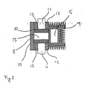
- FIG. 2 a cross section of an inventive arrangement is shown in a mullion-transom construction.
- a cover strip (8) can be seen and on the right side a toe (9).
- the cover strip (8) corresponds essentially to the outer profile section (2) according to the illustration FIG. 1 and the post (9) substantially corresponds to the inner profile section (3) as shown FIG. 1 ,
- the distance between the cover strip (8) and the post (9) is ensured in accordance with the figure 2 by spacers.
- the cover strip (8) and the post (9) serve in the in FIG. 2 illustrated embodiment of the fixation of a glass sheet or a panel (11). Between the cover strip (8) or the post (9) and the glass or the panel (11) seals or insulation (12) are provided.
- the post (9), as well as the profile section (3) of the embodiment according to FIG. 2 a cavity (5).
- the post (9) like the FIG. 2 can be seen, provided on all outer sides with a cooling rib or heat rib profile section to facilitate the heat transfer from the adjacent to the post (9) environment on the post (9).
- the post (9) and the cover strip (8) are in the in FIG. 2 illustrated embodiment formed of aluminum.
- the opposite sides of the cover strip (8) and the post (9) delimit together with the spacer elements (10) an insulation space (13), which is substantially the insulating chamber (1) of the embodiment according to FIG. 1 equivalent.
Landscapes
- Engineering & Computer Science (AREA)
- Civil Engineering (AREA)
- Structural Engineering (AREA)
- Architecture (AREA)
- Building Environments (AREA)
- Undergarments, Swaddling Clothes, Handkerchiefs Or Underwear Materials (AREA)
- Circuits Of Receivers In General (AREA)
- Crushing And Grinding (AREA)
- Load-Bearing And Curtain Walls (AREA)
- Thermally Actuated Switches (AREA)
- Electron Beam Exposure (AREA)
- Thermal Insulation (AREA)
- Wing Frames And Configurations (AREA)
- Paper (AREA)
- Polarising Elements (AREA)
Description
- Die Erfindung betrifft allgemein eine Anordnung wenigstens zweier Profilabschnitte oder Profile, die beispielsweise über eine Isolierkammer miteinander verbunden sind oder in Pfosten-Riegelbauweise ausgeführt werden.
- Es sind allgemein Anordnungen von Profilen bekannt, die beispielsweise bei Fassaden, Fenster-, Türrahmen oder Oberlichtreihen Einsatz finden. Die Anordnung umfaßt meist zwei Profilabschnitte, die über eine Isolier- bzw. Luft- oder Dämmkammer und geeigneten Verbindungsstegen und/oder Dichtungen aus Kunststoff bzw. Gummi miteinander verbunden sind. Dabei grenzt wenigstens ein Profilabschnitt an einen Innenbereich mit einer Temperatur und wenigstens ein Profilabschnitt an einen Außenbereich oder an den Außenbereich gekoppelte Profilabschnitte mit einer anderen Temperatur an.
- Bei bekannten Profilanordnungen ist es grundsätzlich von Nachteil, daß selbst bei einer thermischen Trennung der Profilabschnitte, an dem Profilabschnitt, das an den Innenbereich angrenzt, Kondensatbildung bzw. Schwitzwasserbildung auftritt und dadurch z.B. die Gefahr der Schimmelbildung erhöht wird.
- Aus der
DE 198 59 520 A1 ist eine Pfosten-Riegelanordnung bekannt, bei der Rohrleitungen für warmes oder kaltes Strömungsmedium vorgesehen sind, wobei diesen stirnseitig eine Strahlungsfläche mit mäanderförmiger Profilierung zugeordnet ist. - Es ist daher die Aufgabe der vorliegenden Erfindung, eine Anordnung von Profilabschnittabschnitten oder Profilen derart weiterzubilden, daß eine Kondensatbildung an wenigstens einem der Profilabschnitte/Profile verhindert bzw. verringert wird.
- Diese Aufgabe wird durch die Merkmale des unabhängigen Patentanspruchs 1 gelöst, wobei zweckmäßige Weiterbildungen durch die Merkmale der abhängigen Ansprüche beschrieben sind.
- Insbesondere liegt dem erfindungsgemäßen Konzept eine Anordnung zugrunde mit wenigstens zwei, über eine Isolierkammer miteinander verbundenen Profilabschnitten, wobei die Oberflächen aller der Isolierkammer abgewandten Seiten zumindest eines Profilabschnittes gegenüber der Oberfläche der der Isolierkammer zugewandten Seite vergrößert ist, um einen erleichterten Temperaturübergang zwischen der Umgebung und der der Isolierkammer abgewandten Seite des Profilabschnittes zu ermöglichen. Der hierin verwendete Begriff Profilabschnitt kann sowohl einen Teil eines Profiles, z.B. Hohlprofiles angeben, wie auch ein gesamtes Profil. Wesentlich ist letztendlich, daß durch eine Vergrößerung der Oberfläche aller Seiten, die für einen Temperaturaustausch zwischen der an dem Profilabschnitt mit der vergrößerten Oberfläche angrenzenden Umgebung und dem Profilabschnitt zur Verfügung steht, eine bessere Durchwärmung des Profilabschnitts oder des Profiles erfolgt. Die Temperatur des Profilabschnitts mit der vergrößerten Oberfläche nähert sich dadurch also an die Temperatur der an den Profilabschnitt angrenzenden Umgebung an, so daß die für die Kondensatbildung verantwortliche Temperaturdifferenz verkleinert, im Idealfall vermieden wird. Um den erfindungsgemäßen Effekt zu verbessern, besteht zusätzlich die Möglichkeit, den Profilabschnitt, der dem Innenbereich zugewandt ist, aus einem Material mit einem hohen Temperaturleitwert, hingegen den dem Außenbereich zugewandten Profilabschnitt aus einem Material mit einem niedrigen Temperaturleitwert herzustellen.
- Die vergrößerte Oberfläche der der Isolierkammer abgewandten Seiten sind rippenförmig ausgebildet, wobei die Ausbildung die Form von Kühlrippen bzw. Wärmerippen einnimmt. Eine rippenförmige Geometrie ist beispielsweise mit einem Gußverfahren oder einem Strangpreßverfahren auf einfache Weise herzustellen. Darüber hinaus besteht die Möglichkeit, die Oberfläche der der Isolierkammer abgewandten Seiten durch eine Erhöhung der Oberflächenrauigkeit zu vergrößern.
- In einer bevorzugten Ausführungsform sind im wesentlichen die gesamten der Isolierkammer abgewandten Flächen mit rippenförmiger Profilierung gestaltet. Der erfindungsgemäße Effekt erhöht sich durch die Vergrößerung der Oberfläche, so daß die Ausnutzung der gesamten Flächen, d.h. das Vorsehen von "Wärme- bzw. Kühlrippen" über die gesamte Erstreckung der Flächen, zur Vergrößerung der Oberfläche besonders vorteilhaft ist.
- Weiterhin ist es von Vorteil, wenn die Profilabschnitte selbst zumindest ein Hohlprofil ausbilden. Die Verwendung von Hohlprofilabschnitten ermöglicht eine Senkung des Materialeinsatzes und somit der Materialkosten. Darüber hinaus garantiert die Verwendung von Hohlprofilabschnitten in vorteilhafter Art und Weise eine möglichst einfache Handhabbarkeit der Anordnung, da die gesamte Anordnung bei der Verwendung von Hohlprofilabschnitten ein geringeres Gesamtgewicht aufweist.
- Ferner ist es von Vorteil, wenn zwischen den Profilabschnitten wenigstens zwei Verbindungsstege vorgesehen sind, die die Profilabschnitte miteinander verbinden und mit den zur Isolierkammer gerichteten Seiten der Profilabschnitte die Isolierkammer bilden. Durch die gleichzeitige Verwendung der Verbindungsstege zur Fixierung der Profilabschnitte aneinander, als auch zur Begrenzung der Isolationskammer ergibt sich ein überraschend einfacher und effektiver Aufbau der Gesamtanordnung mit einer Mindestzahl von Bauteilen.
- Weiterhin ist es von Vorteil, wenn die Verbindungsstege aus Kunststoff und die Profilabschnitte aus Aluminium sind. Durch die Verwendung eines Kunststoffes für die Verbindungsstege wird der Isolationseffekt der Isolationskammer zusätzlich erhöht, da Kunststoffe in der Regel eine geringe Temperaturleitfähigkeit aufweisen.
- Weitere Merkmale und Vorteile der Erfindung werden deutlicher beim Lesen der folgenden, lediglich beispielhaften und nicht einschränkenden angeführten Beschreibung, welcher unter Bezugnahme auf die beiliegenden Zeichnungen erfolgt. Darin zeigen:
- Figur 1
- einen Querschnitt einer Anordnung zweier über eine Isolierkammer miteinander verbundener Profilabschnitte.
- Figur 2
- einen Querschnitt einer erfindungsgemäßen Anordnung bei einer Pfosten-Riegelkonstruktion.
- In
Figur 1 ist ein Querschnitt einer Anordnung zweier über eine Isolierkammer 1 miteinander verbundener Profilabschnitte 2, 3 dargestellt, die nicht Gegenstand der Erfindung und ähnlich aufgebaut ist wie, jene, die aus derDE 198 59 520 A1 bekannt ist. Der erste Profilabschnitt 2 ist diametral zum zweiten Profilabschnitt 3 angeordnet, wobei die Profilabschnitte 2, 3 einen im wesentlichen rechteckigen Querschnitt aufweisen. Die Profilabschnitte 2, 3 umschließen jeweils einen Hohlraum 4, 5. Es ist offensichtlich, daß die Profilabschnitte 2, 3 auch einen anderen beliebigen Querschnitt aufweisen können. Darüber hinaus sind die Profilabschnitte 2, 3 inFigur 1 aus Aluminium, wobei auch andere Werkstoffe, wie Kunststoff, Stahl, Holz, usw. Einsatz finden können. - An den zur Isolierkammer 1 gerichteten Seiten der Profilabschnitte 2, 3 sind zwei Verbindungsstege 6, 7 angeordnet, die die Profilabschnitte 2, 3 miteinander verbinden und mit den zur Isolierkammer 1 gerichteten Seiten der Profilabschnitte 2, 3 die Isolierkammer 1 begrenzen bzw. bilden. Die Verbindungsstege 6, 7 sind aus Kunststoff, wobei auch hier andere Werkstoffe zum Einsatz kommen können. Es ist jedoch von Vorteil, wenn die Verbindungsstege 6, 7 gegenüber den Profilabschnitten 2, 3 eine geringere Wärmeleitfähigkeit aufweisen.
- Die Oberfläche der der Isolierkammer 1 abgewandten Seite des zweiten Profilabschnittes 3 ist gegenüber der der Isolierkammer 1 zugewandten Seite vergrößert, um einen erleichterten Temperaturübergang von der Umgebung auf die der Isolierkammer abgewandten Seite des Profilabschnittes 3 zu ermöglichen. In der
Figur 1 wird die Vergrößerung einer der Isolierkammer abgewandten Seite des Profilabschnittes 3 durch eine rippenförmige. Ausbildung der betroffenen Seite erreicht, ähnlich einer Welle mit einer Vielzahl von Wellenbergen und Wellentälern, so daß sich im wesentlichen ein Kühlrippenquerschnitt ergibt, der hier allerdings als Wärmerippe wirkt. - Der erste Profilabschnitt 2 grenzt an einen in
Figur 1 nicht dargestellten Außenbereich, der zweite Profilabschnitt 3 an einen ebenfalls nicht dargestellten Innenbereich. Wenn beispielsweise der Außenbereich ein niedrigeres Temperaturniveau als der Innenbereich aufweist, gleicht sich die Temperatur des ersten Profilabschnitts 2 der Isolierkammer 1 und des zweiten Profilabschnitts 3 soweit an, daß sich ein stabiles Temperaturgefälle über den Querschnitt der Gesamtanordnung einstellt. Dabei sind die jeweiligen Temperaturübergänge Umgebung/Profilabschnitt bzw. Profilabschnitt/Isolierkammer und umgekehrt ausschlaggebend für das sich einstellende Temperaturgefälle. - In der
Figur 2 ist ein Querschnitt einer erfindungsgemäßen Anordnung bei einer Pfosten-Riegelkonstruktion dargestellt. Im wesentlichen ist hier auf der linken Seite eine Deckleiste (8) zu erkennen und auf der rechten Seite ein Pfösten (9). Die Deckleiste (8) entspricht dabei im wesentlichen dem Außenprofilabschnitt (2) der Darstellung nachFigur 1 und der Pfosten (9) entspricht im wesentlichen dem Innenprofilabschnitt (3) der Darstellung nachFigur 1 . - Der Abstand zwischen der Deckleiste (8) und dem Pfosten (9) wird nach Maßgabe der Figur 2 durch Abstandselemente sichergestellt. Die Deckleiste (8) und der Pfosten (9) dienen in der in
Figur 2 dargestellten Ausführungsform der Fixierung einer Glasscheibe bzw. eines Paneels (11). Zwischen der Deckleiste (8) bzw. dem Pfosten (9) und der Glasscheibe bzw den Paneel (11) sind Dichtungen oder Dämmungen (12) vorgesehen. Der Pfosten (9) weist, wie auch der Profilabschnitt (3) der Ausführungsform nachFigur 2 , einen Hohlraum (5) auf. Darüber hinaus ist der Pfosten (9), wie derFigur 2 zu entnehmen ist, auf sämtlichen Außenseiten mit einem Kühlrippen- bzw. Wärmerippen-Profilabschnitt versehen, um den Wärmeübergang von der an den Pfosten (9) angrenzenden Umgebung auf den Pfosten (9) zu erleichtern. Durch die rippenförmige Ausgestaltung der Oberflächen der der Isolierkammer 13 abgewandten Seiten des zweiten Profilabschnitts 9 werden die Seiten mit der vergrößerten Oberfläche derart durchwärmt, daß zwischen dem zweiten Profilabschnitt 9 und dem angrenzenden Bereich eine geringe, im Idealfall keine Temperaturdifferenz vorhanden ist. Der Pfosten (9) als auch die Deckleiste (8) sind in der inFigur 2 dargestellten Ausführungsform dabei aus Aluminium gebildet. Die sich gegenüberliegenden Seiten der Deckleiste (8) und des Pfostens (9) begrenzen zusammen mit den Distanzelementen (10) einen Isolationsraum (13), der im wesentlichen der Isolierkammer (1) der Ausführungsform nachFigur 1 entspricht.
Claims (5)
- Anordnung wenigstens zweier, über eine Isolierkammer (13) miteinander verbundener Profilabschnitte (8, 9), dadurch gekennzeichnet, daß die Oberflächen sämtlicher, der Isolierkammer (13) abgewandten Seiten zumindest eines Profilabschnittes (9) gegenüber der Oberfläche der, der Isolierkammer (13) zugewandten Seite mittels Kühlrippen- bzw. Wärmerippen-Profilabschnitten vergrößert sind, um einen erleichterten Temeraturübergang zwischen der Umgebung und den der Isolierkammer (13) abgewandten Seiten des Profilabschnitts (9) zu ermöglichen.
- Anordnung nach Anspruch 1, dadurch gekennzeichnet, daß zumindest eine der, der Isolierkammer (13) abgewandten Seiten im Wesentlichen in ihrer Gesamtheit rippenförmig ausgebildet ist.
- Anordnung nach einem der Ansprüche 1 oder 2, dadurch gekennzeichnet, daß die Profilabschnitte (8, 9) ein Hohlprofil bilden.
- Anordnung nach einem der Ansprüche 1 bis 3, dadurch gekennzeichnet, daß zwischen zwei Profilabschnitten (8, 9) wenigstens zwei Verbindungsstege (10) und/oder Dichtelemente (12) bei gekoppelten Elementen vorgesehen sind, die mit den Profilabschnitten (8, 9) die Isolierkammer (13) bilden.
- Anordnung nach einem der Ansprüche 1 bis 4, dadurch gekennzeichnet, daß die Verbindungsstege (10) aus Kunststoff und die Profilabschnitte (8, 9) aus Aluminium ausgebildet sind.
Applications Claiming Priority (3)
| Application Number | Priority Date | Filing Date | Title |
|---|---|---|---|
| DE10212341A DE10212341C1 (de) | 2002-03-14 | 2002-03-14 | Profilanordnung |
| DE10212341 | 2002-03-14 | ||
| PCT/DE2003/000836 WO2003078779A1 (de) | 2002-03-14 | 2003-03-14 | Profilanordnung |
Publications (2)
| Publication Number | Publication Date |
|---|---|
| EP1488065A1 EP1488065A1 (de) | 2004-12-22 |
| EP1488065B1 true EP1488065B1 (de) | 2010-06-09 |
Family
ID=7714153
Family Applications (1)
| Application Number | Title | Priority Date | Filing Date |
|---|---|---|---|
| EP03720180A Expired - Lifetime EP1488065B1 (de) | 2002-03-14 | 2003-03-14 | Profilanordnung |
Country Status (6)
| Country | Link |
|---|---|
| US (1) | US20050181176A1 (de) |
| EP (1) | EP1488065B1 (de) |
| AT (1) | ATE470778T1 (de) |
| AU (1) | AU2003223873A1 (de) |
| DE (3) | DE10212341C1 (de) |
| WO (1) | WO2003078779A1 (de) |
Citations (1)
| Publication number | Priority date | Publication date | Assignee | Title |
|---|---|---|---|---|
| EP0320463A1 (de) * | 1987-12-09 | 1989-06-14 | METALLURGICA METRA TRAFILATI ALLUMINIO S.p.A. | Profilsatz für verbundisolierte Tür- oder Fensterrahmen |
Family Cites Families (11)
| Publication number | Priority date | Publication date | Assignee | Title |
|---|---|---|---|---|
| US4439962A (en) * | 1978-07-10 | 1984-04-03 | Wasco Products, Inc. | Skylight construction |
| DE3372005D1 (en) * | 1982-08-05 | 1987-07-16 | Otto Willert | Compound profile |
| SE8205119L (sv) * | 1982-09-09 | 1984-03-10 | Integral Profilsystem Ab | Isolering av aluminiumprofiler i fixtur |
| DE3624849A1 (de) * | 1986-07-23 | 1988-01-28 | Schuermann & Co Heinz | Fenster, tuer oder festverglasung in beschusshemmender ausfuehrung |
| NL8702600A (nl) * | 1987-10-30 | 1989-05-16 | Meijer Sjoerd | Warmtewisselaar en plaatmateriaal daarvoor. |
| DE4421867C1 (de) * | 1994-06-22 | 1995-10-26 | Hueck Eduard Gmbh Co Kg | Verglasungsdichtung |
| DE19704697A1 (de) * | 1997-02-07 | 1998-08-13 | Bosch Siemens Hausgeraete | Vakuumisolationselement |
| DE19731163A1 (de) * | 1997-07-21 | 1999-01-28 | Krueger Ernst Dr | Mehrschichthohlkammerprofil |
| DE19859520A1 (de) * | 1998-12-11 | 2000-06-29 | Christian Fischer | Fensterfassade |
| DE19900518A1 (de) * | 1999-01-08 | 2000-07-13 | Erich Wintermantel | Profilelemente, Profilmodule und Kombinationen von Profilelementen und -modulen mit pastösen, verfestigungsfähigen Beschichtungsmassen zum gerichteten Führen von strömungsfähigen Medien sowie deren Anwendung |
| DE29910537U1 (de) * | 1999-06-16 | 1999-09-30 | Hoogovens Aluminium Profiltechnik Gmbh, 88267 Vogt | Haltevorrichtung für Glasscheiben |
-
2002
- 2002-03-14 DE DE10212341A patent/DE10212341C1/de not_active Expired - Fee Related
-
2003
- 2003-03-14 EP EP03720180A patent/EP1488065B1/de not_active Expired - Lifetime
- 2003-03-14 AT AT03720180T patent/ATE470778T1/de active
- 2003-03-14 DE DE10391015T patent/DE10391015D2/de not_active Expired - Lifetime
- 2003-03-14 DE DE50312797T patent/DE50312797D1/de not_active Expired - Lifetime
- 2003-03-14 AU AU2003223873A patent/AU2003223873A1/en not_active Abandoned
- 2003-03-14 WO PCT/DE2003/000836 patent/WO2003078779A1/de not_active Ceased
- 2003-03-14 US US10/507,675 patent/US20050181176A1/en not_active Abandoned
Patent Citations (1)
| Publication number | Priority date | Publication date | Assignee | Title |
|---|---|---|---|---|
| EP0320463A1 (de) * | 1987-12-09 | 1989-06-14 | METALLURGICA METRA TRAFILATI ALLUMINIO S.p.A. | Profilsatz für verbundisolierte Tür- oder Fensterrahmen |
Also Published As
| Publication number | Publication date |
|---|---|
| DE10391015D2 (de) | 2005-02-10 |
| DE50312797D1 (de) | 2010-07-22 |
| EP1488065A1 (de) | 2004-12-22 |
| DE10212341C1 (de) | 2003-04-24 |
| WO2003078779A1 (de) | 2003-09-25 |
| AU2003223873A1 (en) | 2003-09-29 |
| ATE470778T1 (de) | 2010-06-15 |
| US20050181176A1 (en) | 2005-08-18 |
Similar Documents
| Publication | Publication Date | Title |
|---|---|---|
| EP2472047B1 (de) | Profilanordnung | |
| EP2527580A1 (de) | Isolationseinsatz für einen aus Profilen gebildeten Rahmen | |
| EP0636760A2 (de) | Rahmen füe ein Fenster, einer Tür oder Fassade | |
| DE202010001301U1 (de) | Wärmegedämmtes Verbundprofil | |
| EP0633383B2 (de) | Kunststoffhohlprofil, insbesondere für Fenster- oder Türrahmen | |
| EP1095231B1 (de) | Verfahren zum herstellen eines solarkollektors | |
| EP2743421A1 (de) | Fassade oder Lichtdach, Isoliersteg und Verfahren zum Herstellen eines Isoliersteges | |
| EP2363567B1 (de) | Rahmen eines Kunststofffensters oder einer Kunststofftür | |
| CH690452A5 (de) | Isolationsvorrichtung zur thermischen Trennung von Leichtmetallprofilen im Fensterbau. | |
| DE20107743U1 (de) | Variabel belüftete Garraumtür | |
| EP0742335B1 (de) | Flügelrahmen eines Fensters oder dergleichen | |
| EP0957213A1 (de) | Fugendichtung für Sandwichelemente von Aussenwand- und Dachsystemen | |
| DE102008020988A1 (de) | Wärmeisolierendes Rahmenprofil für die Herstellung von Tür- und Fensterrahmen | |
| EP2487313A1 (de) | Rahmenkonstruktion für ein Fenster oder eine Tür | |
| WO2003078779A1 (de) | Profilanordnung | |
| EP3831569B1 (de) | Verfahren zur herstellung eines kunststoffprofils | |
| CH656669A5 (en) | Window or door construction | |
| DE202007015319U1 (de) | Isolator für Fenster-, Tür- und Fassadensysteme | |
| DE2103904A1 (de) | Metall-Fensterrahmen aus dünnwandigen Blechprofilen | |
| DE2353628A1 (de) | Stranggepresstes heizkoerperglied aus leichtmetall zur herstellung von rohrregisterheizkoerpern | |
| EP4102021B1 (de) | Fenster- oder tür-hohlkammerprofil, system mit einem solchen hohlkammerprofil und daraus hergestellter rahmen | |
| EP3831570B1 (de) | Verfahren zur herstellung eines kunststoff-profils | |
| DE1909128B2 (de) | Heizkörper | |
| DE20204563U1 (de) | Thermisch isolierte Türschwelle | |
| DE20104213U1 (de) | Wärmedämmendes Profilelement für einen Fensterrahmen o.dgl. |
Legal Events
| Date | Code | Title | Description |
|---|---|---|---|
| PUAI | Public reference made under article 153(3) epc to a published international application that has entered the european phase |
Free format text: ORIGINAL CODE: 0009012 |
|
| 17P | Request for examination filed |
Effective date: 20041013 |
|
| AK | Designated contracting states |
Kind code of ref document: A1 Designated state(s): AT BE BG CH CY CZ DE DK EE ES FI FR GB GR HU IE IT LI LU MC NL PT RO SE SI SK TR |
|
| AX | Request for extension of the european patent |
Extension state: AL LT LV MK |
|
| 17Q | First examination report despatched |
Effective date: 20051205 |
|
| GRAP | Despatch of communication of intention to grant a patent |
Free format text: ORIGINAL CODE: EPIDOSNIGR1 |
|
| GRAS | Grant fee paid |
Free format text: ORIGINAL CODE: EPIDOSNIGR3 |
|
| GRAA | (expected) grant |
Free format text: ORIGINAL CODE: 0009210 |
|
| AK | Designated contracting states |
Kind code of ref document: B1 Designated state(s): AT BE BG CH CY CZ DE DK EE ES FI FR GB GR HU IE IT LI LU MC NL PT RO SE SI SK TR |
|
| REG | Reference to a national code |
Ref country code: CH Ref legal event code: EP |
|
| REG | Reference to a national code |
Ref country code: IE Ref legal event code: FG4D Free format text: LANGUAGE OF EP DOCUMENT: GERMAN |
|
| REF | Corresponds to: |
Ref document number: 50312797 Country of ref document: DE Date of ref document: 20100722 Kind code of ref document: P |
|
| REG | Reference to a national code |
Ref country code: NL Ref legal event code: VDEP Effective date: 20100609 |
|
| PG25 | Lapsed in a contracting state [announced via postgrant information from national office to epo] |
Ref country code: SE Free format text: LAPSE BECAUSE OF FAILURE TO SUBMIT A TRANSLATION OF THE DESCRIPTION OR TO PAY THE FEE WITHIN THE PRESCRIBED TIME-LIMIT Effective date: 20100609 |
|
| PG25 | Lapsed in a contracting state [announced via postgrant information from national office to epo] |
Ref country code: FI Free format text: LAPSE BECAUSE OF FAILURE TO SUBMIT A TRANSLATION OF THE DESCRIPTION OR TO PAY THE FEE WITHIN THE PRESCRIBED TIME-LIMIT Effective date: 20100609 Ref country code: SI Free format text: LAPSE BECAUSE OF FAILURE TO SUBMIT A TRANSLATION OF THE DESCRIPTION OR TO PAY THE FEE WITHIN THE PRESCRIBED TIME-LIMIT Effective date: 20100609 |
|
| PG25 | Lapsed in a contracting state [announced via postgrant information from national office to epo] |
Ref country code: CY Free format text: LAPSE BECAUSE OF FAILURE TO SUBMIT A TRANSLATION OF THE DESCRIPTION OR TO PAY THE FEE WITHIN THE PRESCRIBED TIME-LIMIT Effective date: 20100609 Ref country code: GR Free format text: LAPSE BECAUSE OF FAILURE TO SUBMIT A TRANSLATION OF THE DESCRIPTION OR TO PAY THE FEE WITHIN THE PRESCRIBED TIME-LIMIT Effective date: 20100910 |
|
| REG | Reference to a national code |
Ref country code: IE Ref legal event code: FD4D |
|
| PG25 | Lapsed in a contracting state [announced via postgrant information from national office to epo] |
Ref country code: EE Free format text: LAPSE BECAUSE OF FAILURE TO SUBMIT A TRANSLATION OF THE DESCRIPTION OR TO PAY THE FEE WITHIN THE PRESCRIBED TIME-LIMIT Effective date: 20100609 Ref country code: IE Free format text: LAPSE BECAUSE OF FAILURE TO SUBMIT A TRANSLATION OF THE DESCRIPTION OR TO PAY THE FEE WITHIN THE PRESCRIBED TIME-LIMIT Effective date: 20100609 Ref country code: NL Free format text: LAPSE BECAUSE OF FAILURE TO SUBMIT A TRANSLATION OF THE DESCRIPTION OR TO PAY THE FEE WITHIN THE PRESCRIBED TIME-LIMIT Effective date: 20100609 |
|
| PG25 | Lapsed in a contracting state [announced via postgrant information from national office to epo] |
Ref country code: PT Free format text: LAPSE BECAUSE OF FAILURE TO SUBMIT A TRANSLATION OF THE DESCRIPTION OR TO PAY THE FEE WITHIN THE PRESCRIBED TIME-LIMIT Effective date: 20101011 Ref country code: SK Free format text: LAPSE BECAUSE OF FAILURE TO SUBMIT A TRANSLATION OF THE DESCRIPTION OR TO PAY THE FEE WITHIN THE PRESCRIBED TIME-LIMIT Effective date: 20100609 Ref country code: RO Free format text: LAPSE BECAUSE OF FAILURE TO SUBMIT A TRANSLATION OF THE DESCRIPTION OR TO PAY THE FEE WITHIN THE PRESCRIBED TIME-LIMIT Effective date: 20100609 Ref country code: CZ Free format text: LAPSE BECAUSE OF FAILURE TO SUBMIT A TRANSLATION OF THE DESCRIPTION OR TO PAY THE FEE WITHIN THE PRESCRIBED TIME-LIMIT Effective date: 20100609 |
|
| PG25 | Lapsed in a contracting state [announced via postgrant information from national office to epo] |
Ref country code: IT Free format text: LAPSE BECAUSE OF FAILURE TO SUBMIT A TRANSLATION OF THE DESCRIPTION OR TO PAY THE FEE WITHIN THE PRESCRIBED TIME-LIMIT Effective date: 20100609 |
|
| PLBE | No opposition filed within time limit |
Free format text: ORIGINAL CODE: 0009261 |
|
| STAA | Information on the status of an ep patent application or granted ep patent |
Free format text: STATUS: NO OPPOSITION FILED WITHIN TIME LIMIT |
|
| PG25 | Lapsed in a contracting state [announced via postgrant information from national office to epo] |
Ref country code: DK Free format text: LAPSE BECAUSE OF FAILURE TO SUBMIT A TRANSLATION OF THE DESCRIPTION OR TO PAY THE FEE WITHIN THE PRESCRIBED TIME-LIMIT Effective date: 20100609 |
|
| 26N | No opposition filed |
Effective date: 20110310 |
|
| REG | Reference to a national code |
Ref country code: DE Ref legal event code: R097 Ref document number: 50312797 Country of ref document: DE Effective date: 20110309 |
|
| BERE | Be: lapsed |
Owner name: HEINRICH STRUNZ G.M.B.H. Effective date: 20110331 |
|
| PG25 | Lapsed in a contracting state [announced via postgrant information from national office to epo] |
Ref country code: MC Free format text: LAPSE BECAUSE OF NON-PAYMENT OF DUE FEES Effective date: 20110331 |
|
| REG | Reference to a national code |
Ref country code: CH Ref legal event code: PL |
|
| PG25 | Lapsed in a contracting state [announced via postgrant information from national office to epo] |
Ref country code: BE Free format text: LAPSE BECAUSE OF NON-PAYMENT OF DUE FEES Effective date: 20110331 |
|
| PG25 | Lapsed in a contracting state [announced via postgrant information from national office to epo] |
Ref country code: CH Free format text: LAPSE BECAUSE OF NON-PAYMENT OF DUE FEES Effective date: 20110331 Ref country code: LI Free format text: LAPSE BECAUSE OF NON-PAYMENT OF DUE FEES Effective date: 20110331 |
|
| REG | Reference to a national code |
Ref country code: AT Ref legal event code: MM01 Ref document number: 470778 Country of ref document: AT Kind code of ref document: T Effective date: 20110314 |
|
| PG25 | Lapsed in a contracting state [announced via postgrant information from national office to epo] |
Ref country code: AT Free format text: LAPSE BECAUSE OF NON-PAYMENT OF DUE FEES Effective date: 20110314 |
|
| PG25 | Lapsed in a contracting state [announced via postgrant information from national office to epo] |
Ref country code: LU Free format text: LAPSE BECAUSE OF NON-PAYMENT OF DUE FEES Effective date: 20110314 |
|
| PG25 | Lapsed in a contracting state [announced via postgrant information from national office to epo] |
Ref country code: BG Free format text: LAPSE BECAUSE OF FAILURE TO SUBMIT A TRANSLATION OF THE DESCRIPTION OR TO PAY THE FEE WITHIN THE PRESCRIBED TIME-LIMIT Effective date: 20100909 Ref country code: TR Free format text: LAPSE BECAUSE OF FAILURE TO SUBMIT A TRANSLATION OF THE DESCRIPTION OR TO PAY THE FEE WITHIN THE PRESCRIBED TIME-LIMIT Effective date: 20100609 |
|
| PG25 | Lapsed in a contracting state [announced via postgrant information from national office to epo] |
Ref country code: HU Free format text: LAPSE BECAUSE OF FAILURE TO SUBMIT A TRANSLATION OF THE DESCRIPTION OR TO PAY THE FEE WITHIN THE PRESCRIBED TIME-LIMIT Effective date: 20100609 Ref country code: ES Free format text: LAPSE BECAUSE OF FAILURE TO SUBMIT A TRANSLATION OF THE DESCRIPTION OR TO PAY THE FEE WITHIN THE PRESCRIBED TIME-LIMIT Effective date: 20100920 |
|
| REG | Reference to a national code |
Ref country code: FR Ref legal event code: PLFP Year of fee payment: 14 |
|
| REG | Reference to a national code |
Ref country code: FR Ref legal event code: PLFP Year of fee payment: 15 |
|
| REG | Reference to a national code |
Ref country code: FR Ref legal event code: PLFP Year of fee payment: 16 |
|
| PGFP | Annual fee paid to national office [announced via postgrant information from national office to epo] |
Ref country code: GB Payment date: 20220328 Year of fee payment: 20 Ref country code: DE Payment date: 20220315 Year of fee payment: 20 |
|
| PGFP | Annual fee paid to national office [announced via postgrant information from national office to epo] |
Ref country code: FR Payment date: 20220324 Year of fee payment: 20 |
|
| REG | Reference to a national code |
Ref country code: DE Ref legal event code: R071 Ref document number: 50312797 Country of ref document: DE |
|
| REG | Reference to a national code |
Ref country code: GB Ref legal event code: PE20 Expiry date: 20230313 |
|
| PG25 | Lapsed in a contracting state [announced via postgrant information from national office to epo] |
Ref country code: GB Free format text: LAPSE BECAUSE OF EXPIRATION OF PROTECTION Effective date: 20230313 |