EP1488074B1 - Procede et appareil de bouchage - Google Patents
Procede et appareil de bouchage Download PDFInfo
- Publication number
- EP1488074B1 EP1488074B1 EP03745328A EP03745328A EP1488074B1 EP 1488074 B1 EP1488074 B1 EP 1488074B1 EP 03745328 A EP03745328 A EP 03745328A EP 03745328 A EP03745328 A EP 03745328A EP 1488074 B1 EP1488074 B1 EP 1488074B1
- Authority
- EP
- European Patent Office
- Prior art keywords
- passageway
- carrier
- plug
- gaps
- portions
- Prior art date
- Legal status (The legal status is an assumption and is not a legal conclusion. Google has not performed a legal analysis and makes no representation as to the accuracy of the status listed.)
- Expired - Lifetime
Links
Images





Classifications
-
- E—FIXED CONSTRUCTIONS
- E21—EARTH OR ROCK DRILLING; MINING
- E21B—EARTH OR ROCK DRILLING; OBTAINING OIL, GAS, WATER, SOLUBLE OR MELTABLE MATERIALS OR A SLURRY OF MINERALS FROM WELLS
- E21B33/00—Sealing or packing boreholes or wells
- E21B33/10—Sealing or packing boreholes or wells in the borehole
- E21B33/13—Methods or devices for cementing, for plugging holes, crevices or the like
- E21B33/134—Bridging plugs
-
- E—FIXED CONSTRUCTIONS
- E21—EARTH OR ROCK DRILLING; MINING
- E21B—EARTH OR ROCK DRILLING; OBTAINING OIL, GAS, WATER, SOLUBLE OR MELTABLE MATERIALS OR A SLURRY OF MINERALS FROM WELLS
- E21B33/00—Sealing or packing boreholes or wells
- E21B33/10—Sealing or packing boreholes or wells in the borehole
- E21B33/12—Packers; Plugs
- E21B33/1204—Packers; Plugs permanent; drillable
Definitions
- the present invention relates to a method and apparatus for plugging a passageway.
- Such passageways include underground components which may be plugged to prevent leakage of hydrocarbon fluids from those components.
- Plugs can be inserted at any point in a well, for example adjacent the surface or at a substantial depth.
- plugs are formed by injecting cement or resin into the well so as to fill for example a fifty metre length of the well.
- Experience has proved however that such plugs are not particularly reliable and often leak.
- the known plugs tend to leak for a variety of reasons. Firstly, as the well wall is typically not particularly clean and is also covered with a hydrocarbon flm, it is difficult to produce a reliable contiguous seal. Often a contiguous seal of only a metre or so in length is formed with a plug fifty times that length. Furthermore, as cement and resin based plugs solidify they contract which tends to open up a gap between the plug and the well wall. Although when a plug is initially inserted there may be little dynamic pressure in the well, after the plug is in situ substantial pressures can build up and as a result a plug which appears initially to be working satisfactory may subsequently be found to leak.
- US 2,191,783 describes a bridging plug for a well casing.
- the plug includes a body member of cylindrical form having an annular channel provided in its outer surface.
- the channel is adapted to receive a non-explosive exothermic mixture such as thermite.
- thermite mixture Upon ignition, the thermite mixture generates a high temperature, and flows outwardly into contact with the surrounding casing, fusing to the surrounding casing, and leaving a residue which is welded to the body and the casing.
- US 2,298,129 describes a method of bringing about the deposition of a scaling deposit within the pores of an earth or rock formation, by displacing molten metal from the well bore into the formation, and introducing a relatively cold fluid into the well to bring about solidification of the metal.
- the metal may be capable of expanding upon solidification.
- the material when molten is arranged so as to occupy a space between fins extending radially from a tubular carrier, the peripheral edges of the fins being a sliding fit within the well (for example leaving a gap or drift of approximately 1/16 of an inch). This does constrain to a certain extent both axial flow of the molten material and subsequent creep over time of the solidified metal, but some metal can flow through the gaps around the fins.
- an apparatus for forming a plug in a passageway comprising a carrier which in use is lowered into the passageway, the carrier comprising an elongate body of a material resistant to creep which supports at least two spaced apart portions that are a sliding fit in the passageway such that a gap is formed between each of the portions and the passageway, a body of material the melting point of which is higher than the temperature within the passageway and which expands as it solidifies, the body of material being supported on the carrier, and means for melting the body of material such that melted material fills a space defined between the first and second portions, wherein means are provided to obstruct the gaps formed between the portions and the passageway, the obstructing means being displaced into the gaps as a result of melting of the body of material or as a result of creep of material after it has been melted and solidified.
- the invention also provides a method for forming a plug in a passageway, wherein a carrier is placed in the passageway, the carrier defining an elongate body of material resistant to creep which supports at least two spaced apart portions that are a sliding fit in the passageway such that a gap is formed between each of the portions and the passageway, a body of material the melting point of which is higher than the temperature within the passageway and which expands as it solidifies is melted in the passageway to fill a space defined between the spaced apart portions, and the carrier is cooled such that molten material adjacent the spaced apart portions solidifies before molten material between the spaced apart portions.
- the invention ensures that the molten material as it solidifies and expands cannot simply flow past the spaced apart portions of the carrier. This ensures that the expanding material is forced against the wall of the passageway, resulting in a good seal. Furthermore, as the carrier is manufactured from a material which is resistant to creep, the dimensions of the carrier will not change over time even if it is exposed to pressure for many years. In addition, the solidified material is constrained by the carrier and in particular cannot flow between the carrier and the passageway wall as a result of the gaps between the carrier and the passageway wall being obstructed.
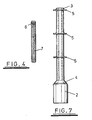
- an assembly described in international patent application No. GB01/04260 is illustrated.
- the assembly is used to form a bismuth alloy plug within a wall casing 1 above a packer 2.
- the solid bismuth alloy plug is formed from an amount of bismuth alloy delivered in solid form on a carrier spool to the required depth within the casing 1.
- the carrier spool may comprise 1% manganese steel and is therefore resistant to elongation as a result of creep.
- the carrier spool comprises a tubular mandrel 3.
- the mandrel 3 has an upper open end.
- the lower end of the mandrel 3 terminates in a head 4, upon which the cylindrical packer 2 (comprising for example a vulcanised rubber including 40% acrylonitrile, or a simple steel skirt) is mounted.
- the packer 2 may be mounted on the head by a method which includes a bonding step, thus forming a metallelastic bond.
- the head 4 defines a frustocone the base of which has a smaller diameter than that of the packer 2 and which tapers from the upper surface of the packer 2 to the mandrel 3.
- the mandrel 3 has a plurality of circular flanges defining fins 5 distributed at intervals along its length. The diameter of each fin 5 is approximately equal to the diameter of the base of the frustocone 4.
- metal to be melted to form a plug locates along the length of the mandrel 3 between the head 4 and an upper fin 5, defining a cylinder extending as far as the peripheral edge of the upper fin 5.
- the metal may comprise, for example, pure bismuth, an admixture of 95% bismuth and 5% tin, or an admixture of 52% bismuth and 48% tin. In each case the metal may be doped with sodium.
- the carrier spool is inserted into the casing 1 (packer end first) and lowered to the required depth.
- the bismuth alloy is melted in situ by a heater which normally locates within the mandrel 3 (but which is illustrated for clarity in figure 4 outside the mandrel 3).
- the heater defines a cylinder, an upper portion of which comprises an ignition source 6 and a lower portion of which comprises a heater element 7.
- the heater element 7 may comprise an admixture of aluminium and iron oxide (thermit mixture).
- the ignition source 6 may comprise a barium peroxide fuse and an electrical heater. It will be appreciated that other forms of both ignition source 6 and heater element 7 could be used.
- the ignition source 6 is activated using a fuse 8 (figure 5).
- the fuse 8 is preferably disposed in a bore 9 in a threaded cap 10 which engages a threaded portion 11 of the mandrel 3.
- the cap 10 may define a simple hollow plug (as shown in figure 5) or may include features such as incisions 12 (as shown in figure 6) which allow the cap 10 to be engaged by other equipment (not shown) such as a deployment tool.
- the cap 10 may define a stab connector.
- Activation of the ignitor 6 triggers the heater element 7.
- Heat produced from the heater element 7 causes the bismuth alloy supported on the mandrel 3 to become molten.
- Combustion/waste gases which may be produced from the heater element 7 are allowed to be vented by the open end of the mandrel 3 and the cap 10.
- the molten bismuth alloy thus slumps into the volume defined by the upper surface of the rubber packer 2 and the casing wall 1 (as shown in figure 1), filling the volume defined between the head 4 and the two lower fins 5.
- the frustocone 4 is able to serve as a wedge that drives into the expanded bismuth alloy plug. Thus pressure from the reservoir serves to force the plug 6 against the casing wall 1.
- the fins 5 serve three purposes. Firstly the fins 5 aid in forcing the expanding metal against the casing 1 by minimising axial and promoting lateral expansion. Secondly the fins 5 aid the transfer of heat from the heater element 7 to the bismuth alloy. Thirdly the fins 5 aid in reducing creep of the bismuth alloy plug up hole.
- the fins 5 are a sliding fit within the well casing 1 and therefore relatively small gaps are defined between the casing and the peripheral edges of the fins 5 (and the peripheral edge of the frustocone 4). This gap is generally referred to as the "drift".
- the molten metal cools and solidifies, it expands. In the absence of the fins 5, much of this expansion would simply result in molten metal flowing upwards in the axial direction. This would not contribute to the formational of a plug tightly compressed within the casing.
- the fins 5 reduce this flow, hence improving the security of the plug.
- the present invention is concerned with improving the effect of the presence of the fins 5.
- the effect of the fins 5 is increased by introducing a coolant into the carrier body defined by the mandrel 3 after the plug material has been melted. This will cause material adjacent the mandrel 3 to solidify first, and thereafter cooling will be accelerated around the fins 5.
- molten material in the gaps between the peripheries of the fins 5 and the casing 1 will solidify relatively rapidly, that solidincation occurring before a substantial portion of the melted material has a chance to solidify.
- That still molten material is as a result effectively trapped between the frustocone 4 and fins 5 and as it cools and solidifies all the resultant expansion contributes to the application of pressure to the casing 1.
- a very tight plug is achieved.
- Coolant can be delivered to the mandrel 3 in any convenient manner. For example, simply by ensuring that the casing above the plug is filled with water is generally sufficient providing that, after the heater element 7 has been ignited and the plug material has been melted, water can penetrate into the mandrel 3, rapidly cooling the mandrel 3 and the fins 5. This approach automatically delivers the cooling water to the required location as soon as the metal which forms the plug has been melted. It will appreciated however that alternative methods for delivering coolant to the mandrel 3 could be envisaged, for example by the provision of body of coolant which is released a predetermined period after ignition of the heater element 7.
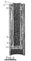
- FIG 8 is a photograph of a section through an experimental plug manufactured using a structure generally similar to that illustrated in figures 1 to 7 and relying upon water to rapidly cool the mandrel 3.
- only two fins 5 were provided. It can be seen that the gaps between the outer edges of the fins 5 and the casing 1 are filled with the material making up the plug and that given the width of the fins 5 and the cooling effect of the presence of water inside the mandrel 3 the material formed within the gaps around the fins 5 will cool rapidly and certainly before much of the material trapped between the two fins 5 or between the lower fin 5 and the frustocone 4 has solidified. Subsequent solidification will therefore result in the expanding plug material exerting substantial forces against the casing 1.
- the material making up the plug will be under compression and, given its nature, will tend to flow as a result of creep.
- the fins 5 obstruct such flow, thereby ensuring that the plug does not fail rapidly.
- some flow may occur however through the narrow gaps defined between the fins 5 and the casing 1 it may be that after a very prolonged period in situ the plug may flow to such an extent that it cannot maintain the required seal with the casing 1.
- the present invention has as one of its objectives the solution of this problem by obstructing the flow of material between the fins 5 and the casing 1.
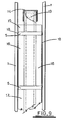
- this shows an alternative structure to that shown in figures 1 to 7 but of the same general configuration, that is an axially extending mandrel 3 supporting fins 5.
- the mandrel 3 receives a heating element of the same general type as that described with reference to figure 7 but the fuse structure is modified to ensure rapid penetration of coolant into the mandrel 3 after the heating element has been activated and the plug material has melted. It will be appreciated that with the fuse assemblies of figures 5 and 6 water penetration may be obstructed to an extent by the cap 10 unless the cap 10 is displaced or destroyed in the heating process.
- a pyrophoric fuse 13 forms the heating element in the mandrel 3, that fuse being initiated through a fusible cap 14 which extends over the open upper end of the mandrel 3.
- the arrangement is such that the cap 14 remains intact until the plug material has been melted.
- the fuse 13 may be initiated at its lowermost end such that, by the time the fuse 13 has melted the cap 14, enough material to form a plug has been melted. Igniting the fuse 13 it its bottom end provides more time for melting to occur.
- the mandrel 3 supports three hollow cylindrical bodies of the material which is to be melted to form the plug, that is an upper body 15 located above the upper fin 5, an intermediate body 16 located between the fins 5, and a lower body 17 which will be located between the lower fin 5 and the frustocone at the base of the assembly.
- the frustocone is not shown in figures 9 and 10.
- a gap 18 is formed between the casing 1, the peripheral edges of the fins 5 and the bodies of material 15, 16 and 17. This gap 18 will be filled with water if the casing 1 is filled with water when the assembly of figure 9 is inserted.
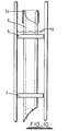
- this shows the plug in its final form after melting and subsequent solidification of the bodies 15, 16 and 17.
- the result is a solid plug with an upper solidified surface 19.
- the fusible cap 14 melts as a result of heating by the pyrophoric fuse 13. After the fuse 13 has been consumed and the cap 14 ruptured the mandrel 3 defines an empty open ended tube into which water within the casing 1 can flow. Any water initially located in the gap 18 between the inserted assembly and the casing will be displaced by the molten material which forms the plug. Thus, when the heating element is energised, the material forming the plug melts and flows into the small gap around the inserted assembly. There is a small flow of the material downwards around the fins 5.
- the fins 5 will offer substantial resistance to creep of the plug material past the fins given the relatively narrow gaps 18 around the peripheral edges of the fins. This gap can be further reduced in magnitude however by arranging for it to be obstructed by devices which are embedded in the plug.
- Figures 11 to 14 illustrate one modification to the structure shown in figures 9 and 10 which achieves blocking of the gaps around the fins.
- Figures 9 & 10 do not show a structure such as the stab connector shown in Figure 6 to enable the assembly to be connected to a device for lowering the assembly into the well.
- a structure will of course be provided, the structure being designed in form or manufactured from a material such that it will not obstruct the flooding of the mandrel 3 after melting of the plug material.
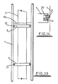
- the illustrated assembly is essentially the same as that shown in figure 9 except for the formation of grooves 20 in the peripheral edges of the fins 5 and the incorporation into each of those grooves of a double-turn ring 21.
- the ring 21 is formed of a memory metal such that when heated as a result of melting of the plug material the ring springs outwards so as to obstruct the gap 18 between the peripheral edge of the fins 5 and the casing 1.
- Figures 13 and 14 illustrate the outward expansion of the rings which occurs after the plug is formed. It can be seen that the ring 21 substantially obstructs the gap between the fin 5 in which it is initially housed and the casing 1. Thus flow of molten material is further restricted and creep of the material forming the plug after it has been solidified is substantially prevented.
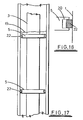
- Figures 15 to 18 illustrate an alternative ring arrangement to that shown in figures 12 to 14.
- a single C-shaped ring 22 is formed in the groove 20 defined by the fin 5.
- the ring 22 could be formed of a memory metal which causes the ring to open after heating of the assembly.
- the C-shaped ring could simply be pre-sprung but initially restrained so as to be held within the groove 20, the spring 22 being released as a result of heating of the assembly.
- the ring 22 could be secured in position by an adhesive which itself melts when the assembly is heated.
- the ring 22 could incorporate for example a bimetallic strip which causes the ring to open when heated. Thus on melting of the material to form the plug the ring will open and the ring will be held in its open condition by the solidified material and will not therefore retract back into the groove 20.
- the body of material 16 located between the fins 5 could have embedded within it particulates such as balls which will move into the gaps adjacent the fins 5 when the material 16 is melted.
- the body could incorporate "floating" balls of steel or aluminium and “sinking" balls of for example tungsten so that when the material is melted the floating balls will move upwards adjacent the upper fin 5 and the sinking balls will sink downwards adjacent the lower fin 5.
- the axially facing surfaces of the fins 5 could be frustoconical (as in the structure shown in figure 9) to encourage migration of the balls into the gaps adjacent the peripheral edges of the fins 5.
- magnetism Rather than replying upon gravity to appropriately position particulates, it would be possible in some applications to rely upon magnetism, for exanzple by embedding magnetised particles within the material to be melted, the magnetised particles migrating towards the gaps around the peripheral edges of the fins 5 as soon as the material is melted. It would also be possible to use magnetism in other ways to displace gap-obstructing components. For example, magnetic C-rings could be constrained in a position such that, after melting of the plug material and consequent release of the constraint, the C-rings are displaced into a position in which they obstruct the gaps.
- C-shaped horseshoe magnets could be positioned such that each extends around 120° of the edge of a fin, the magnets being arranged end to end with opposed polarities and embedded in the plug material adjacent the fin. When the plug material melts, the rings will be pushed apart by repulsive magnetic forces.
- particulates which are spherical they will not fully seal the gaps around the fins but nevertheless will siguificantly obstruct flow through those gaps as a result of creep.
- the particulates could be of a configuration other than spherical however, the only requirement being that each of the particles is too large to pass through the gap between the fins and the casing.
- gap will be of the order of 1/16 of an inch assuming that the assembly is cental within the casing and therefore particulates of say 1/4 inch outside diameter will be sufficiently large to ensure that they will not be able to pass through the gaps around the peripheral edges of the fins 5.
- devices could be mounted on the fins 5 or the mandrel 3 which are constrained to move in a particular manner.
- three arms could be pivotally mounted on the mandrel 3 at points spaced at interval of 120°, each of the arms supporting a blocking member which is moveable outwards towards the periphery of an adjacent fin, the blocking member being dimensioned and located so that when brought to a position adjacent the fin it blocks approximately 1/3 of the circumference of the gap around the periphery of that fin. Movement of the blocking members into a gap-blocking position could be ensured by manufacturing them of a material which "floats" or "sinks" as appropriate after the material forming the plug has been melted.
- each of the fins could support a peripheral skirt extending in the axial direction from the outer edge of the fin. That peripheral skirt would be embedded in the plug after it has solidified. Creep of the plug material towards the gap around the fin would carry the skirt with it, causing th e skirt to flare outwards, thereby blocking the gap.
- an L-section annular blocking member 23 has been provided below the upper fin 5 and both above and below the lower fin 5.
- the member 23 could be formed of for example steel so that if it was forced outwards relative to the fin 5 as a result of flow of the solidified material such flow would rapidly be obstructed. It will be noted that an arrangement such as that shown in figure 19 does not rely upon gravity and would be effective in any orieniation.
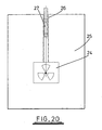
- figure 20 illustrates nuclear waste located in a cavity 24 in a block of material 25.
- the block of material 25 is impermeable to radiation and could, for example, include concrete and/or lead or alternatively a carbon-steel material.
- a passageway 26 is formed through the block of material 25 to allow the introduction of the nuclear waste into the cavity 24.
- a plug 27 may be formed in the passageway 26 using the techniques described above.
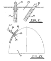
- Figure 21 shows a further embodiment of the present invention.
- passageways 28 are formed in a solid base 29 of for example concrete.
- Such passageways can be created by drilling holes into the base. If desired, the holes may be lined in a known manner so as to form smoothly lined passageways.
- the carriers 30 are inserted into respective passageways 28 and plugs are created in the manner described above. Thereafter, objects such as cables or the like (not shown) may be connected to the carriers 30 which are anchored to the solid base 29 by the formation of plugs.
- Applications of this further embodiment of the invention may include, for example, the securing of a civil engineering structure such as bridge to a rock.
- Figure 22 illustrates a tunnel 31 formed through a body of rock 32. It is known to attach roof bolts through walls of a tunnel so as to prevent subsidence of rock into the tunnel.
- the present invention provides a convenient way of reliably attaching such bolts.
- a passageway 33 is formed into the body of rock 32.
- a carrier 34 carrying a washer 35 and a nut 36 at one end is inserted into the passageway, such that the washer 35 and the nut 36 protrude into the tunnel 31, and the washer bears against the wall of the tunnel 31.
- the carrier 34 is then attached to the walls of the passageway 33 by the formation of a plug in the manner described above, so as to reliably fix the carrier 34 into the rock.
- the nut 36 is tightened, thereby ensuring that the washer 35 presses against the rock to resist subsidence.
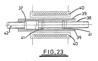
- FIG 23 illustrates a tubular member in which a passageway 37 is formed.
- a carrier 38 is fixed in the tubular member so as to plug the passageway 37.
- Sidewalls 39 of the passageway 37 are surrounded by a tubular heating element 40.
- the carrier 38 supports fins 41 between which material (not shown) may be melted and then solidified to form a plug in the passageway.
- the tubular member may be connected to one element 42 and the carrier 38 may be connected to a second element (not shown) to enable secure interconnection of the two elements.
- the carrier 38 If the two elements are to be separated, it is necessary to remove the carrier 38 from the passageway 37. This can be achieved by energising the heating element 40 to melt the solidified material, thereby allowing the carrier 38 to be removed from the passageway 37. Given that much of the molten material will be positioned to the right hand side of at least one of two fins 41 provided by the carrier 38, much of the molten material will be removed from the passageway 37 along with the carrier 38. In an alternative embodiment, the solidified material may be melted by ignition of a suitable fuse mixture provided within the carrier.
- a chain link can be formed from two parts which are joined using two of the arrangements illustrated in figure 23. Heaters can then be used to separate the two parts, thereby allowing a chain link to be broken.
Landscapes
- Geology (AREA)
- Life Sciences & Earth Sciences (AREA)
- Engineering & Computer Science (AREA)
- Mining & Mineral Resources (AREA)
- Environmental & Geological Engineering (AREA)
- Fluid Mechanics (AREA)
- Physics & Mathematics (AREA)
- General Life Sciences & Earth Sciences (AREA)
- Geochemistry & Mineralogy (AREA)
- Processing Of Solid Wastes (AREA)
- Auxiliary Devices For And Details Of Packaging Control (AREA)
- Heating, Cooling, Or Curing Plastics Or The Like In General (AREA)
- Making Paper Articles (AREA)
- Processing And Handling Of Plastics And Other Materials For Molding In General (AREA)
Claims (22)
- Appareil destiné à former un bouchon dans une voie de passage, l'appareil comprenant un support qui est en utilisation abaissé à l'intérieur de la voie de passage (1), le support comprenant un corps allongé (3) d'un matériau qui supporte au moins deux parties espacées (5) qui forment un ajustement coulissant dans la voie de passage (1) de sorte qu'un espace est formé entre chacune des parties (5) et la voie de passage (1), un corps de matériau (15, 16, 17) dont le point de fusion est supérieur à la température à l'intérieur de la voie de passage, le corps de matériau étant supporté sur le support (3), et des moyens (6, 7) destinés à faire fondre le corps de matériau de sorte que le matériau fondu remplisse un espace défini entre la première et la seconde partie (5),
caractérisé en ce que le matériau du corps allongé est résistant au fluage, en ce que le matériau du corps de matériau se dilate en solidifiant, et en ce que des moyens (21 ; 22 ; 23) sont apportés pour obturer les espaces formés entre les parties et la voie de passage, les moyens d'obturation étant déplacés à l'intérieur des espaces en conséquence de la fusion du corps de matériau ou en conséquence du fluage de matériau suite à sa fusion et à sa solidification. - Appareil selon la revendication 1, dans lequel les moyens d'obturation comprennent des anneaux (21 ; 22) logés dans des rainures (20) dans les parties espacées (5), les anneaux étant déplacés dans les espaces en conséquence de la fusion du corps de matériau.
- Appareil selon la revendication 2, dans lequel au moins un anneau (21) comprend des enroulements chevauchants.
- Appareil selon la revendication 2, dans lequel chaque anneau (22) est en forme de C.
- Appareil selon la revendication 2, 3 ou 4, dans lequel chaque anneau (21 ; 22) est formé d'un métal à mémoire de forme qui amène l'anneau à se dilater lorsque l'anneau est chauffé en conséquence de la fusion du corps de matériau.
- Appareil selon la revendication 2, 3 ou 4, dans lequel chaque anneau (21 ; 22) est initialement fixé dans la rainure et libéré en conséquence de la fusion du corps de matériau, l'anneau étant entraîné à sauter de manière à se déplacer vers l'extérieur par rapport à la rainure lorsqu'il est libéré.
- Appareil selon la revendication 2, 3 ou 4, dans lequel chaque anneau (21 ; 22) est formé au moins en partie sous forme de bande bimétallique laquelle, lorsqu'elle est chauffée suite à la fusion du corps de matériau, entraîne le déplacement vers l'extérieur de l'anneau par rapport à la rainure.
- Appareil selon la revendication 1, dans lequel les moyens d'obturation comprennent des composants qui sont disposés de manière à flotter ou à couler dans les espaces lorsque le matériau est fondu.
- Appareil selon la revendication 8, dans lequel les composants sont des matières patticulaires qui sont plus grandes que les espaces, les matières particulaires étant libres de se déplacer à l'intérieur du matériau fondu.
- Appareil selon la revendication 9, dans lequel les matières particulaires sont des perles magnétiques dont la magnétisation est telle que les perles émigrent vers les espaces lorsque le matériau est fondu.
- Appareil selon la revendication 8, dans lequel les composants sont couplés au corps de support de sorte à pouvoir se déplacer le long de trajectoires prédéterminées par rapport au corps et formés de manière à obturer des parties des espaces.
- Appareil selon la revendication 1, dans lequel les moyens d'obturation comprennent des jupes (23) s'étendant à partir des parties espacées jusqu'à l'intérieur de l'espace les séparant, de sorte que les jupes sont encastrées dans du matériau solidifié suite à la formation du bouchon et sont positionnées de sorte que tout fluage du matériau solidifié fait dévier les jupes vers l'extérieur pour obturer les espaces.
- Appareil selon l'une quelconque des revendications précédentes, dans lequel les parties espacées sont définies par des ailettes (5) s'étendant dans un sens radial vers l'extérieur du corps allongé.
- Appareil selon l'une quelconque des revendications précédentes, dans lequel le corps allongé (3) est tubulaire.
- Appareil selon la revendication 14, dans lequel le corps tubulaire (3) reçoit un élément chauffant.
- Appareil selon l'une quelconque des revendications précédentes, dans lequel la voie de passage est un puits.
- Appareil selon l'une quelconque des revendications 1 à 15, dans lequel un objet est attaché de manière fixe au support, de sorte qu'après la solidification du matériau, l'objet est attaché de manière fixe à la voie de passage.
- Appareil selon l'une quelconque des revendications précédentes, comprenant des moyens chauffants (40) destinés à faire fondre le matériau solidifié, permettant ainsi au support (38) d'être retiré de la voie de passage (37).
- Procédé de formation d'un bouchon dans une voie de passage, dans lequel un support est placé dans la voie de passage (1), le support définissant un corps allongé (3) de matériau qui supporte au moins deux parties espacées (5) qui forment un ajustement coulissant dans la voie de passage de sorte qu'un espace est formé entre chacune des parties (5) et la voie de passage (1), un corps de matériau (15, 16, 17) dont le point de fusion est supérieur à la température à l'intérieur de la voie de passage, est fondu dans la voie de passage pour remplir un espace défini par les parties espacées,
caractérisé en ce que le matériau du corps allongé est résistant au fluage, en ce que le matériau du corps de matériau se dilate en solidifiant, et en ce que le support est refroidi de sorte que le matériau fondu adjacent aux parties espacées (5) se solidifie avant le matériau fondu entre les parties espacées. - Procédé selon la revendication 19, dans lequel le support comprend un corps tubulaire allongé à partir duquel font saillie les parties espacées, et le support est refroidi par introduction de réfrigérant à l'intérieur du corps tubulaire.
- Procédé selon la revendication 20, dans lequel le réfrigérant est de l'eau au-dessus du bouchon dans la voie de passage.
- Procédé selon la revendication 19, 20 ou 21, dans lequel la voie de passage est un puits.
Applications Claiming Priority (3)
| Application Number | Priority Date | Filing Date | Title |
|---|---|---|---|
| GBGB0207371.6A GB0207371D0 (en) | 2002-03-28 | 2002-03-28 | Sealing method and apparatus |
| GB0207371 | 2002-03-28 | ||
| PCT/GB2003/001293 WO2003083255A1 (fr) | 2002-03-28 | 2003-03-26 | Procede et appareil de bouchage |
Publications (2)
| Publication Number | Publication Date |
|---|---|
| EP1488074A1 EP1488074A1 (fr) | 2004-12-22 |
| EP1488074B1 true EP1488074B1 (fr) | 2006-08-09 |
Family
ID=9933932
Family Applications (1)
| Application Number | Title | Priority Date | Filing Date |
|---|---|---|---|
| EP03745328A Expired - Lifetime EP1488074B1 (fr) | 2002-03-28 | 2003-03-26 | Procede et appareil de bouchage |
Country Status (7)
| Country | Link |
|---|---|
| US (1) | US20050199307A1 (fr) |
| EP (1) | EP1488074B1 (fr) |
| AT (1) | ATE335911T1 (fr) |
| AU (1) | AU2003226512A1 (fr) |
| DE (1) | DE60307444D1 (fr) |
| GB (1) | GB0207371D0 (fr) |
| WO (1) | WO2003083255A1 (fr) |
Families Citing this family (12)
| Publication number | Priority date | Publication date | Assignee | Title |
|---|---|---|---|---|
| US7290609B2 (en) * | 2004-08-20 | 2007-11-06 | Cinaruco International S.A. Calle Aguilino De La Guardia | Subterranean well secondary plugging tool for repair of a first plug |
| US7124820B2 (en) * | 2004-08-20 | 2006-10-24 | Wardlaw Louis J | Exothermic tool and method for heating a low temperature metal alloy for repairing failure spots along a section of a tubular conduit |
| CA2688704C (fr) * | 2009-12-15 | 2016-04-26 | Rawwater Engineering Company Limited | Procede et appareil de scellement |
| GB201010998D0 (en) * | 2010-06-30 | 2010-08-18 | Rawwater Engineering Company Ltd | Sealing method and apparatus |
| NO334723B1 (no) * | 2012-03-12 | 2014-05-12 | Interwell Technology As | Fremgangsmåte for å plugge og forlate en brønn |
| GB201223055D0 (en) * | 2012-12-20 | 2013-02-06 | Carragher Paul | Method and apparatus for use in well abandonment |
| GB201414565D0 (en) * | 2014-08-15 | 2014-10-01 | Bisn Oil Tools Ltd | Methods and apparatus for use in oil and gas well completion |
| EP3029261B1 (fr) * | 2014-12-02 | 2019-05-22 | Services Pétroliers Schlumberger | Procédés de déploiement d'outils pour assurer l'isolation eutectique de bouchons de puits de forage |
| CN106522871B (zh) * | 2015-09-15 | 2019-04-05 | 中国石油化工股份有限公司 | 一种裸眼封隔器 |
| US11365611B2 (en) | 2017-05-01 | 2022-06-21 | Conocophillips Company | Metal seal for liner drilling |
| US11149517B2 (en) * | 2019-01-02 | 2021-10-19 | ISOL8 (Holdings) Limited | Expanding thermite reactions for downhole applications |
| NO347280B1 (en) | 2021-06-25 | 2023-08-21 | Interwell Norway As | Downhole millable permanent plug |
Family Cites Families (27)
| Publication number | Priority date | Publication date | Assignee | Title |
|---|---|---|---|---|
| US3273641A (en) * | 1966-09-20 | Method and apparatus for completing wells | ||
| US1631419A (en) * | 1926-06-04 | 1927-06-07 | Myron M Kinley | Apparatus for plugging wells |
| US2298129A (en) * | 1938-03-29 | 1942-10-06 | Dow Chemical Co | Treatment of wells |
| US2191783A (en) * | 1939-07-15 | 1940-02-27 | Lane Wells Co | Bridging plug |
| US2363269A (en) * | 1939-07-29 | 1944-11-21 | Schlumberger Well Surv Corp | Method for sealing borehole casings |
| US2942668A (en) * | 1957-11-19 | 1960-06-28 | Union Oil Co | Well plugging, packing, and/or testing tool |
| US3333635A (en) * | 1964-04-20 | 1967-08-01 | Continental Oil Co | Method and apparatus for completing wells |
| US3208530A (en) * | 1964-09-14 | 1965-09-28 | Exxon Production Research Co | Apparatus for setting bridge plugs |
| NL133950C (fr) * | 1966-02-03 | |||
| US3419074A (en) * | 1966-06-10 | 1968-12-31 | Otis Eng Co | Well tools |
| US3420928A (en) * | 1966-07-15 | 1969-01-07 | Otis Eng Corp | Method of producing seals |
| US3578084A (en) * | 1969-06-23 | 1971-05-11 | Exxon Production Research Co | Thermal well completion method and apparatus |
| US3738424A (en) * | 1971-06-14 | 1973-06-12 | Big Three Industries | Method for controlling offshore petroleum wells during blowout conditions |
| US3765486A (en) * | 1971-06-24 | 1973-10-16 | Shell Oil Co | Well blowout confinement with dense balls |
| US3891034A (en) * | 1974-01-08 | 1975-06-24 | Gearhart Owen Industries | Through-tubing bridge plug having covered expansible packer |
| US4024916A (en) * | 1976-08-05 | 1977-05-24 | The United States Of America As Represented By The United States Energy Research And Development Administration | Borehole sealing method and apparatus |
| US4275788A (en) * | 1980-01-28 | 1981-06-30 | Bj-Hughes Inc. | Method of plugging a well |
| US4487432A (en) * | 1981-10-19 | 1984-12-11 | Perfection Corporation | No-hole insertion joint |
| US4484750A (en) * | 1982-07-01 | 1984-11-27 | Dresser Industries, Inc. | High pressure seal joint |
| US4489784A (en) * | 1983-02-02 | 1984-12-25 | Messenger Joseph U | Well control method using low-melting alloy metals |
| GB8725670D0 (en) * | 1987-11-03 | 1987-12-09 | Reed Tool Co | Manufacture of rotary drill bits |
| US5137283A (en) * | 1991-06-27 | 1992-08-11 | Itt Corporation | Thermally conductive gasket device |
| US5621844A (en) * | 1995-03-01 | 1997-04-15 | Uentech Corporation | Electrical heating of mineral well deposits using downhole impedance transformation networks |
| US5607017A (en) * | 1995-07-03 | 1997-03-04 | Pes, Inc. | Dissolvable well plug |
| IL152456A0 (en) * | 2000-04-24 | 2003-05-29 | Shell Int Research | Method for treating a hydrocarbon-cotaining formation |
| GB0023543D0 (en) * | 2000-09-26 | 2000-11-08 | Rawwater Engineering Company L | Sealing method and apparatus |
| MY130896A (en) * | 2001-06-05 | 2007-07-31 | Shell Int Research | In-situ casting of well equipment |
-
2002
- 2002-03-28 GB GBGB0207371.6A patent/GB0207371D0/en not_active Ceased
-
2003
- 2003-03-26 AU AU2003226512A patent/AU2003226512A1/en not_active Abandoned
- 2003-03-26 DE DE60307444T patent/DE60307444D1/de not_active Expired - Lifetime
- 2003-03-26 WO PCT/GB2003/001293 patent/WO2003083255A1/fr not_active Ceased
- 2003-03-26 EP EP03745328A patent/EP1488074B1/fr not_active Expired - Lifetime
- 2003-03-26 US US10/509,272 patent/US20050199307A1/en not_active Abandoned
- 2003-03-26 AT AT03745328T patent/ATE335911T1/de not_active IP Right Cessation
Also Published As
| Publication number | Publication date |
|---|---|
| DE60307444D1 (de) | 2006-09-21 |
| US20050199307A1 (en) | 2005-09-15 |
| AU2003226512A1 (en) | 2003-10-13 |
| WO2003083255A1 (fr) | 2003-10-09 |
| GB0207371D0 (en) | 2002-05-08 |
| ATE335911T1 (de) | 2006-09-15 |
| EP1488074A1 (fr) | 2004-12-22 |
Similar Documents
| Publication | Publication Date | Title |
|---|---|---|
| CA2688635C (fr) | Procede et appareil de scellement | |
| EP1339943B1 (fr) | Procede et appareil d'obturation d'un puits | |
| US6474414B1 (en) | Plug for tubulars | |
| US20200011150A1 (en) | Method and Apparatus for Use in Well Abandonment | |
| US20050199307A1 (en) | Sealing method and apparatus | |
| US20060144591A1 (en) | Method and apparatus for repair of wells utilizing meltable repair materials and exothermic reactants as heating agents | |
| CA3119702A1 (fr) | Outil agrandissable en profondeur de forage a base d'alliage eutectique et procedes de deploiement de celui-ci | |
| US11098553B2 (en) | Method for sealing a region of open hole gravel pack | |
| CA2864808A1 (fr) | Abandon de puits en faisant fondre des materiaux avoisinants | |
| GB2586796A (en) | Downhole barrier | |
| US20230147260A1 (en) | Downhole expandable tubular | |
| EP4180619A1 (fr) | Élément tubulaire extensible de fond de trou | |
| CA2840538C (fr) | Procede et appareil d'etancheite | |
| EP4359638B1 (fr) | Bouchon permanent pouvant être fraisé en fond de trou et procédé de réglage d'un bouchon permanent pouvant être fraisé en fond de trou | |
| CN118574978A (zh) | 井下可膨胀管结构 | |
| GB2608269A (en) | An expandable eutectic alloy based downhole tool and methods of deploying such |
Legal Events
| Date | Code | Title | Description |
|---|---|---|---|
| PUAI | Public reference made under article 153(3) epc to a published international application that has entered the european phase |
Free format text: ORIGINAL CODE: 0009012 |
|
| 17P | Request for examination filed |
Effective date: 20040927 |
|
| AK | Designated contracting states |
Kind code of ref document: A1 Designated state(s): AT BE BG CH CY CZ DE DK EE ES FI FR GB GR HU IE IT LI LU MC NL PT RO SE SI SK TR |
|
| AX | Request for extension of the european patent |
Extension state: AL LT LV MK |
|
| GRAP | Despatch of communication of intention to grant a patent |
Free format text: ORIGINAL CODE: EPIDOSNIGR1 |
|
| GRAS | Grant fee paid |
Free format text: ORIGINAL CODE: EPIDOSNIGR3 |
|
| GRAA | (expected) grant |
Free format text: ORIGINAL CODE: 0009210 |
|
| AK | Designated contracting states |
Kind code of ref document: B1 Designated state(s): AT BE BG CH CY CZ DE DK EE ES FI FR GB GR HU IE IT LI LU MC NL PT RO SE SI SK TR |
|
| PG25 | Lapsed in a contracting state [announced via postgrant information from national office to epo] |
Ref country code: IT Free format text: LAPSE BECAUSE OF FAILURE TO SUBMIT A TRANSLATION OF THE DESCRIPTION OR TO PAY THE FEE WITHIN THE PRESCRIBED TIME-LIMIT;WARNING: LAPSES OF ITALIAN PATENTS WITH EFFECTIVE DATE BEFORE 2007 MAY HAVE OCCURRED AT ANY TIME BEFORE 2007. THE CORRECT EFFECTIVE DATE MAY BE DIFFERENT FROM THE ONE RECORDED. Effective date: 20060809 Ref country code: CZ Free format text: LAPSE BECAUSE OF FAILURE TO SUBMIT A TRANSLATION OF THE DESCRIPTION OR TO PAY THE FEE WITHIN THE PRESCRIBED TIME-LIMIT Effective date: 20060809 Ref country code: SK Free format text: LAPSE BECAUSE OF FAILURE TO SUBMIT A TRANSLATION OF THE DESCRIPTION OR TO PAY THE FEE WITHIN THE PRESCRIBED TIME-LIMIT Effective date: 20060809 Ref country code: FI Free format text: LAPSE BECAUSE OF FAILURE TO SUBMIT A TRANSLATION OF THE DESCRIPTION OR TO PAY THE FEE WITHIN THE PRESCRIBED TIME-LIMIT Effective date: 20060809 Ref country code: RO Free format text: LAPSE BECAUSE OF FAILURE TO SUBMIT A TRANSLATION OF THE DESCRIPTION OR TO PAY THE FEE WITHIN THE PRESCRIBED TIME-LIMIT Effective date: 20060809 Ref country code: LI Free format text: LAPSE BECAUSE OF FAILURE TO SUBMIT A TRANSLATION OF THE DESCRIPTION OR TO PAY THE FEE WITHIN THE PRESCRIBED TIME-LIMIT Effective date: 20060809 Ref country code: BE Free format text: LAPSE BECAUSE OF FAILURE TO SUBMIT A TRANSLATION OF THE DESCRIPTION OR TO PAY THE FEE WITHIN THE PRESCRIBED TIME-LIMIT Effective date: 20060809 Ref country code: AT Free format text: LAPSE BECAUSE OF FAILURE TO SUBMIT A TRANSLATION OF THE DESCRIPTION OR TO PAY THE FEE WITHIN THE PRESCRIBED TIME-LIMIT Effective date: 20060809 Ref country code: SI Free format text: LAPSE BECAUSE OF FAILURE TO SUBMIT A TRANSLATION OF THE DESCRIPTION OR TO PAY THE FEE WITHIN THE PRESCRIBED TIME-LIMIT Effective date: 20060809 Ref country code: CH Free format text: LAPSE BECAUSE OF FAILURE TO SUBMIT A TRANSLATION OF THE DESCRIPTION OR TO PAY THE FEE WITHIN THE PRESCRIBED TIME-LIMIT Effective date: 20060809 |
|
| REG | Reference to a national code |
Ref country code: GB Ref legal event code: FG4D |
|
| REG | Reference to a national code |
Ref country code: CH Ref legal event code: EP |
|
| REG | Reference to a national code |
Ref country code: IE Ref legal event code: FG4D |
|
| REF | Corresponds to: |
Ref document number: 60307444 Country of ref document: DE Date of ref document: 20060921 Kind code of ref document: P |
|
| PG25 | Lapsed in a contracting state [announced via postgrant information from national office to epo] |
Ref country code: SE Free format text: LAPSE BECAUSE OF FAILURE TO SUBMIT A TRANSLATION OF THE DESCRIPTION OR TO PAY THE FEE WITHIN THE PRESCRIBED TIME-LIMIT Effective date: 20061109 Ref country code: BG Free format text: LAPSE BECAUSE OF FAILURE TO SUBMIT A TRANSLATION OF THE DESCRIPTION OR TO PAY THE FEE WITHIN THE PRESCRIBED TIME-LIMIT Effective date: 20061109 Ref country code: DK Free format text: LAPSE BECAUSE OF FAILURE TO SUBMIT A TRANSLATION OF THE DESCRIPTION OR TO PAY THE FEE WITHIN THE PRESCRIBED TIME-LIMIT Effective date: 20061109 |
|
| PG25 | Lapsed in a contracting state [announced via postgrant information from national office to epo] |
Ref country code: DE Free format text: LAPSE BECAUSE OF FAILURE TO SUBMIT A TRANSLATION OF THE DESCRIPTION OR TO PAY THE FEE WITHIN THE PRESCRIBED TIME-LIMIT Effective date: 20061110 |
|
| PG25 | Lapsed in a contracting state [announced via postgrant information from national office to epo] |
Ref country code: ES Free format text: LAPSE BECAUSE OF FAILURE TO SUBMIT A TRANSLATION OF THE DESCRIPTION OR TO PAY THE FEE WITHIN THE PRESCRIBED TIME-LIMIT Effective date: 20061120 |
|
| PG25 | Lapsed in a contracting state [announced via postgrant information from national office to epo] |
Ref country code: PT Free format text: LAPSE BECAUSE OF FAILURE TO SUBMIT A TRANSLATION OF THE DESCRIPTION OR TO PAY THE FEE WITHIN THE PRESCRIBED TIME-LIMIT Effective date: 20070109 |
|
| REG | Reference to a national code |
Ref country code: CH Ref legal event code: PL |
|
| EN | Fr: translation not filed | ||
| PLBE | No opposition filed within time limit |
Free format text: ORIGINAL CODE: 0009261 |
|
| STAA | Information on the status of an ep patent application or granted ep patent |
Free format text: STATUS: NO OPPOSITION FILED WITHIN TIME LIMIT |
|
| 26N | No opposition filed |
Effective date: 20070510 |
|
| PG25 | Lapsed in a contracting state [announced via postgrant information from national office to epo] |
Ref country code: MC Free format text: LAPSE BECAUSE OF NON-PAYMENT OF DUE FEES Effective date: 20070331 Ref country code: IE Free format text: LAPSE BECAUSE OF NON-PAYMENT OF DUE FEES Effective date: 20070326 |
|
| PG25 | Lapsed in a contracting state [announced via postgrant information from national office to epo] |
Ref country code: FR Free format text: LAPSE BECAUSE OF FAILURE TO SUBMIT A TRANSLATION OF THE DESCRIPTION OR TO PAY THE FEE WITHIN THE PRESCRIBED TIME-LIMIT Effective date: 20070511 Ref country code: GR Free format text: LAPSE BECAUSE OF FAILURE TO SUBMIT A TRANSLATION OF THE DESCRIPTION OR TO PAY THE FEE WITHIN THE PRESCRIBED TIME-LIMIT Effective date: 20061110 |
|
| PG25 | Lapsed in a contracting state [announced via postgrant information from national office to epo] |
Ref country code: EE Free format text: LAPSE BECAUSE OF FAILURE TO SUBMIT A TRANSLATION OF THE DESCRIPTION OR TO PAY THE FEE WITHIN THE PRESCRIBED TIME-LIMIT Effective date: 20060809 |
|
| PG25 | Lapsed in a contracting state [announced via postgrant information from national office to epo] |
Ref country code: FR Free format text: LAPSE BECAUSE OF FAILURE TO SUBMIT A TRANSLATION OF THE DESCRIPTION OR TO PAY THE FEE WITHIN THE PRESCRIBED TIME-LIMIT Effective date: 20060809 |
|
| PG25 | Lapsed in a contracting state [announced via postgrant information from national office to epo] |
Ref country code: LU Free format text: LAPSE BECAUSE OF NON-PAYMENT OF DUE FEES Effective date: 20070326 Ref country code: CY Free format text: LAPSE BECAUSE OF FAILURE TO SUBMIT A TRANSLATION OF THE DESCRIPTION OR TO PAY THE FEE WITHIN THE PRESCRIBED TIME-LIMIT Effective date: 20060809 |
|
| PG25 | Lapsed in a contracting state [announced via postgrant information from national office to epo] |
Ref country code: TR Free format text: LAPSE BECAUSE OF FAILURE TO SUBMIT A TRANSLATION OF THE DESCRIPTION OR TO PAY THE FEE WITHIN THE PRESCRIBED TIME-LIMIT Effective date: 20060809 Ref country code: HU Free format text: LAPSE BECAUSE OF FAILURE TO SUBMIT A TRANSLATION OF THE DESCRIPTION OR TO PAY THE FEE WITHIN THE PRESCRIBED TIME-LIMIT Effective date: 20070210 |
|
| PGFP | Annual fee paid to national office [announced via postgrant information from national office to epo] |
Ref country code: GB Payment date: 20220203 Year of fee payment: 20 |
|
| PGFP | Annual fee paid to national office [announced via postgrant information from national office to epo] |
Ref country code: NL Payment date: 20220215 Year of fee payment: 20 |
|
| REG | Reference to a national code |
Ref country code: NL Ref legal event code: MK Effective date: 20230325 |
|
| REG | Reference to a national code |
Ref country code: GB Ref legal event code: PE20 Expiry date: 20230325 |
|
| PG25 | Lapsed in a contracting state [announced via postgrant information from national office to epo] |
Ref country code: GB Free format text: LAPSE BECAUSE OF EXPIRATION OF PROTECTION Effective date: 20230325 |