EP1488086B1 - Systeme de combustion faible a sec dote d'un moyen permettant d'eliminer le bruit de combustion - Google Patents
Systeme de combustion faible a sec dote d'un moyen permettant d'eliminer le bruit de combustion Download PDFInfo
- Publication number
- EP1488086B1 EP1488086B1 EP03711450A EP03711450A EP1488086B1 EP 1488086 B1 EP1488086 B1 EP 1488086B1 EP 03711450 A EP03711450 A EP 03711450A EP 03711450 A EP03711450 A EP 03711450A EP 1488086 B1 EP1488086 B1 EP 1488086B1
- Authority
- EP
- European Patent Office
- Prior art keywords
- fuel
- combustor
- gas
- flow
- premixers
- Prior art date
- Legal status (The legal status is an assumption and is not a legal conclusion. Google has not performed a legal analysis and makes no representation as to the accuracy of the status listed.)
- Expired - Lifetime
Links
Images


Classifications
-
- F—MECHANICAL ENGINEERING; LIGHTING; HEATING; WEAPONS; BLASTING
- F23—COMBUSTION APPARATUS; COMBUSTION PROCESSES
- F23R—GENERATING COMBUSTION PRODUCTS OF HIGH PRESSURE OR HIGH VELOCITY, e.g. GAS-TURBINE COMBUSTION CHAMBERS
- F23R3/00—Continuous combustion chambers using liquid or gaseous fuel
- F23R3/28—Continuous combustion chambers using liquid or gaseous fuel characterised by the fuel supply
- F23R3/34—Feeding into different combustion zones
- F23R3/346—Feeding into different combustion zones for staged combustion
-
- F—MECHANICAL ENGINEERING; LIGHTING; HEATING; WEAPONS; BLASTING
- F23—COMBUSTION APPARATUS; COMBUSTION PROCESSES
- F23D—BURNERS
- F23D14/00—Burners for combustion of a gas, e.g. of a gas stored under pressure as a liquid
- F23D14/46—Details
- F23D14/72—Safety devices, e.g. operative in case of failure of gas supply
- F23D14/82—Preventing flashback or blowback
-
- F—MECHANICAL ENGINEERING; LIGHTING; HEATING; WEAPONS; BLASTING
- F23—COMBUSTION APPARATUS; COMBUSTION PROCESSES
- F23R—GENERATING COMBUSTION PRODUCTS OF HIGH PRESSURE OR HIGH VELOCITY, e.g. GAS-TURBINE COMBUSTION CHAMBERS
- F23R3/00—Continuous combustion chambers using liquid or gaseous fuel
- F23R3/02—Continuous combustion chambers using liquid or gaseous fuel characterised by the air-flow or gas-flow configuration
- F23R3/04—Air inlet arrangements
- F23R3/10—Air inlet arrangements for primary air
- F23R3/12—Air inlet arrangements for primary air inducing a vortex
-
- F—MECHANICAL ENGINEERING; LIGHTING; HEATING; WEAPONS; BLASTING
- F23—COMBUSTION APPARATUS; COMBUSTION PROCESSES
- F23R—GENERATING COMBUSTION PRODUCTS OF HIGH PRESSURE OR HIGH VELOCITY, e.g. GAS-TURBINE COMBUSTION CHAMBERS
- F23R3/00—Continuous combustion chambers using liquid or gaseous fuel
- F23R3/28—Continuous combustion chambers using liquid or gaseous fuel characterised by the fuel supply
- F23R3/286—Continuous combustion chambers using liquid or gaseous fuel characterised by the fuel supply having fuel-air premixing devices
-
- F—MECHANICAL ENGINEERING; LIGHTING; HEATING; WEAPONS; BLASTING
- F23—COMBUSTION APPARATUS; COMBUSTION PROCESSES
- F23R—GENERATING COMBUSTION PRODUCTS OF HIGH PRESSURE OR HIGH VELOCITY, e.g. GAS-TURBINE COMBUSTION CHAMBERS
- F23R3/00—Continuous combustion chambers using liquid or gaseous fuel
- F23R3/42—Continuous combustion chambers using liquid or gaseous fuel characterised by the arrangement or form of the flame tubes or combustion chambers
- F23R3/44—Combustion chambers comprising a single tubular flame tube within a tubular casing
-
- F—MECHANICAL ENGINEERING; LIGHTING; HEATING; WEAPONS; BLASTING
- F05—INDEXING SCHEMES RELATING TO ENGINES OR PUMPS IN VARIOUS SUBCLASSES OF CLASSES F01-F04
- F05B—INDEXING SCHEME RELATING TO WIND, SPRING, WEIGHT, INERTIA OR LIKE MOTORS, TO MACHINES OR ENGINES FOR LIQUIDS COVERED BY SUBCLASSES F03B, F03D AND F03G
- F05B2260/00—Function
- F05B2260/96—Preventing, counteracting or reducing vibration or noise
-
- F—MECHANICAL ENGINEERING; LIGHTING; HEATING; WEAPONS; BLASTING
- F23—COMBUSTION APPARATUS; COMBUSTION PROCESSES
- F23R—GENERATING COMBUSTION PRODUCTS OF HIGH PRESSURE OR HIGH VELOCITY, e.g. GAS-TURBINE COMBUSTION CHAMBERS
- F23R2900/00—Special features of, or arrangements for continuous combustion chambers; Combustion processes therefor
- F23R2900/00014—Reducing thermo-acoustic vibrations by passive means, e.g. by Helmholtz resonators
-
- F—MECHANICAL ENGINEERING; LIGHTING; HEATING; WEAPONS; BLASTING
- F23—COMBUSTION APPARATUS; COMBUSTION PROCESSES
- F23R—GENERATING COMBUSTION PRODUCTS OF HIGH PRESSURE OR HIGH VELOCITY, e.g. GAS-TURBINE COMBUSTION CHAMBERS
- F23R2900/00—Special features of, or arrangements for continuous combustion chambers; Combustion processes therefor
- F23R2900/03342—Arrangement of silo-type combustion chambers
Definitions
- the present invention relates generally to gas turbine engine combustors, and more particularly, in one form, to a dry low emission combustion system that utilizes swirling and jet flows within the combustion chamber to provide stable aerodynamics.
- Air pollution emissions are an undesirable by-product from the operation of a gas turbine engine that burns fossil fuels.
- the primary air polluting emissions produced by the burning of fossil fuels include carbon dioxide, water vapor, oxides of nitrogen, carbon monoxide, unburned hydrocarbons, oxides of sulfur and particulate.
- carbon dioxide and water vapor are generally not considered objectionable.
- air pollution has become a worldwide concern and many nations have enacted stricter laws regarding the discharge of pollutants into the environment.
- Oxides of Nitrogen are one of the pollutants that have been of particular concern to gas turbine engine designers. It is well known that in a gas turbine engine the oxidation of nitrogen is dependent upon the flame temperature within the combustion region.
- a premixing section within the combustor prepares a combustible mixture upstream of the flame front, and therefore the combustor includes provisions to keep the flame from entering or igniting within the premixing section.
- the residence time and velocities within the premixing section are manipulated to discourage auto-ignition and flashback. As a result of this manipulation the residence time is many times limited, which results in incomplete mixing with increased NOx emission. Further, in many systems the burning temperatures are low enough that Carbon Monoxide (CO) emissions are increased.
- CO Carbon Monoxide
- Examples of combustors which include tubular premixer delivering fuel and air to the combustion chamber are disclosed in US 2001/004515 and US 5,450,725 .
- a combustor for burning a fuel and a gas mixture, comprising: a mechanical housing; a combustion chamber located within said mechanical housing and having a first end and a second end and an internal volume; a radial inflow swirler located at said first end and disposed in flow communication with said internal volume, said radial inflow swirler including a plurality of first fuel dispensers for delivering the fuel into the gas within said swirler and a plurality of vanes for directing the fuel and gas flow into the internal volume to define a swirler flow; wherein said combustion chamber has a primary burning region, and said radial inflow swirler delivers fuel and gas into said primary burning region; and characterised by a first plurality of circumferentially spaced fuel and gas tubular premixers connected to said combustion chamber and in flow communication with said internal volume, each of said first plurality of fuel and gas tubular premixers adapted to deliver a premixed jet flow of the gas and fuel into said primary burning region.
- a dome may be positioned at the first end of the combustion chamber and extending into the internal volume, the dome having an outer surface contoured to minimize flow separation of the swirling flow of fuel and gas passing from the premixer and into the combustion chamber.
- the dome may extend along the circumference of the first end and have a convex cross-section.
- the combustor chamber is cylindrical having a portion with a constant cross- sectional area, the combustor chamber having a plurality of first apertures in the portion and a plurality of second apertures in the portion, and the plurality of first apertures are axially spaced from the plurality of second apertures; a plurality of first tubular premixers are coupled to the combustor chamber, each of the plurality of first tubular premixers is in flow communication with one of the plurality of first apertures; and, a plurality of second tubular premixers coupled to the combustor chamber, each of the plurality of second tubular premixers is in flow communication with one of the plurality of second apertures.
- the tubular premixers may each comprise a tubular member having a first end and a second end and a flow passageway therebetween; a fuel manifold disposed in fluid communication with the flow passageway for the delivery of a fuel into the flow passageway; and, twist mixer means for rotating the fluid flowing within the flow passageway, the twist mixer means positioned within the flow passageway.
- the said combustor may include: a combustor liner having a fist end, a second end and said internal volume; a premixer coupled to the first end of the combustor liner and disposed in flow communication with the internal volume, the premixer including a radial inflow swirler having a plurality of fueling passages for delivering the fuel into the air within the swirler and a plurality of vanes for directing the fuel and air flow from the premixer ; a center body having at least a portion positioned within the premixer and located within a space defined between the plurality of vanes; a dome disposed between the first end of the combustor liner and the premixer, the dome having an outer surface contoured to minimize flow separation of the fuel and air flowing from the premixer into the internal volume; a plurality of first tubular premixers coupled to the combustor liner, each of the
- One object of the present invention is to provide a unique combustion system.
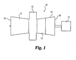
- an industrial gas turbine engine 10 comprising a compressor section 11, a combustion section 12, a turbine section 13 and a power turbine section 14.
- the industrial gas turbine engine 10 includes an inlet 15 for receiving a flow of air and an exhaust 16.
- the turbine section 13 is configured to drive the compressor section 11 via one or more shafts (not illustrated).
- the power turbine section 14 is arranged to drive an auxiliary device 17.
- Auxiliary devices include an electric generator or other devices known to be powered by industrial gas turbine engines. It is important to realize that there are a multitude of ways in which the components can be linked together. Additional compressors and turbines could be added with intercoolers connecting between the compressors and reheat combustion chambers could be added between the turbines.
- the present inventions is designed to be utilized in a wide variety of gas turbine engines and are not intended to be limited to the engines illustrated herrein unless specifically provided to the contrary.
- the general operation of the gas turbine engine 10 is quite conventional and will not be discussed further.
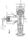
- a side elevational view of an industrial gas turbine engine 10 which includes at least one dry, low emission silo combustor module 20.
- the present invention relates to engines having a plurality of dry low emission silo combustor modules 20.
- the engine includes between 3 and 10 modules. However, the number of modules utilized will generally be selected to meet the system design parameters.
- the silo combustor modules 20 are located off the centerline X of the engine, and the centerline Y of the silo combustor module 20 is substantially orthogonal to the centerline X of the engine.
- the silo combustor modules 20 are oriented at other angles of inclination to the centerline X of the engine.
- the description set forth herein is focused on the silo combustor modules and associated methods of operation and will not focus upon the interaction with the remainder of the gas turbine engine.
- the compressor section 11 increases the pressure of the inlet air and a portion of the air is directed into the silo combustor module 20 as indicated by the arrows "A".
- the pressurized air is introduced into the internal volume 21 of the combustion chamber 22.
- the silo combustor module 20 includes a mechanical housing 23 that surrounds the combustion chamber 22 and is coupled to the gas turbine engine 10.
- a plurality of fueling lines 24 is connected to a fuel source 26.
- the fuel is a natural gas, however other fuels including low energy gaseous fuels and liquid hydrocarbon fuels are contemplated herein.
- the present invention will be described in terms of utilizing air and fuel for the combustion process, however other gases than air, such as the gas turbine engine exhaust are also contemplated herein.
- High temperature working fluid exits the internal volume 21 of the combustion chamber 22 and passes through a duct 27 to the turbine section.
- the mechanical duct to integrate the flow of working fluid from the silo combustor module 20 to the gas turbine engine is contemplated as being a sheet metal construction with traditional mechanical joints and cooling techniques.
- the duct functions to collect the gas from each of the silo combustor modules and deliver into the annular turbine inlet.
- the duct is generally shaped from a circular cross section to an annular cross section. Further, the present invention contemplates other geometry's such as but not limited to a scroll geometry.
- Silo combustor module 20 includes the combustor assembly 28 that is disposed within the mechanical housing 23.
- the combustor assembly 28 is mechanically connected to the mechanical housing 23.
- a fluid flow passageway 29 surrounds the combustor assembly 28 and facilitates the passage of air from the compressor to the assembly 28.
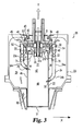
- the combustor assembly 28 includes the combustion chamber 22, a swirler 30, a fueling manifold system 31, a dome 32, at least one primary tubular premixer 33, and at least one secondary tubular premixer 34.
- the swirler 30 is defined by a radial inflow swirler having a plurality of swirler vanes, however the present invention contemplates other swirlers, such as, but not limited to, axial flow swirlers.
- a centerbody 35 is positioned in a space defined between the plurality of vanes 36, which comprises a portion of the radial inflow swirler 30.
- the centerbody 35 is utilized to control the swirler core flow from the radial inflow swirler. It is understood that the actual position of the centerbody 35 may be changed to adjust the flame structure, burning rate and noise associated therewith.
- the centerbody 35 includes an igniter 37a and a pilot fuel injector 37b. Alternate embodiments of the present invention contemplate that some of the above components may not be utilized in a particular design
- the air from the compressor flows through the passageway 29 around the combustor assembly 28 and enters into the radial inflow swirler 30 through a radial inflow swirler inlet 40.
- Radial inflow swirler inlet 40 is distributed circumferentially around the radial inflow swirler 30 and allows the passage of the air into the swirler 30 and between the plurality of vanes 36.
- a plurality of fuel dispensers 41 extend along the axial length of the plurality of vanes 36. Each of the plurality of fuel dispensers 41 have a plurality of fuel discharge openings to dispense fuel into the air flowing in the channels defined between the plurality of vanes 36.
- the air and fuel is mixed within the radial inflow swirler 30 as it passes between the plurality of vanes 36 and the mixture passes out of the radial inflow swirler 30 at outlet 42.
- the present application contemplates that the terms mixing and mixture contemplate a broad meaning that includes partial and/or complete mixing.
- the discharged mixture of fuel and air from the swirler 30 has a mono-directional swirl as it passes into the internal volume 21 of the combustion chamber 22.
- the mixture swirls in a clockwise direction as it exits the swirler as viewed from top of the combustor looking downstream.
- the present invention contemplates that the swirl direction can be clockwise or counterclockwise.
- Fuel is delivered to the plurality of fuel dispensers 41 by a manifolding system 43.
- the fuel and air mixture from the radial inflow swirler 30 passes into the internal volume 21 of the combustion chamber 22 in a mono-directional swirling flow.
- the air and fuel flow passes over a contoured dome 32 that extends between the radial inflow swirler 30 and the combustion chamber 22.
- an annular flow path is defined between the centerbody 35 and the dome 44.
- the outer surface 44 of the dome 32 has a geometric shape designed to minimize the flow separation of the fuel and air mixture leaving the radial inflow swirler 30 and entering the combustion chamber 22.
- the outer surface 44 has a convex configuration, and in a more preferred form, the flow path converges and then diverges utilizing a geometric configuration defined by a quart.
- the dome 32 has the outer surface defined on an annular ring that extends into the internal volume 21.
- the dome 32 has an annular wall member 70 that is spaced from the wall of the combustion chamber 22.
- a space 71 is defined between the wall of the combustion chamber 22 and the dome 32.
- the space 71 provides an insulating environment and allows for the compensation for differentials in thermal expansion.
- the centerbody 35 is spaced from and extends along a portion of the dome 44.
- the plurality of primary tubular premixers 33 have an inlet end 45 adapted to allow the passage of air into the tubular premixers 33. In one form of the present invention there are between 3 and 6 primary tubular premixers, however the present invention also contemplates other quantities outside of this range Primary tubular premixers 33 are coupled to and extend along the combustion chamber 22 and are adapted to deliver a mixture of fuel and air into the internal volume 21 of the combustion chamber 22 through an outlet 46. In one form of the present invention the plurality of primary tubular premixers 33 are spaced circumferentially around the outside of the combustion chamber, and in a more preferred form are evenly spaced.
- the tube of the primary tubular premixer includes a substantial portion 33a that extends parallel to a centerline of the combustion chamber 22. A secondary portion 33b forms a curved piece that couples to the combustion chamber's wall.
- the combustion chamber 22 includes a plurality of openings 75 defined in the combustion chamber wall and adapted to receive the discharge from outlet 46.
- Fluid passing through the plurality of primary tubular premixers 33 enters the internal volume 21 in a substantially radial direction.
- the primary tubular premixers include a mechanical mixer within its flow passageway.
- Each of the plurality of primary tubular premixers 33 delivers the fuel and air mixture into the internal volume 21 at a location such that the discharged jets of fuel and air interact with the swirling flow of fuel and air from the radial inflow swirler 30. It is preferred that the fuel and air mixture delivered from each of the primary tubular premixers have a significant radial direction component.
- the flow of fuel and air from the plurality of primary tubular premixers is at least fifteen percent of the fuel and air flow from the swirler.
- the interaction of the swirling fuel and air from the radial inflow swirler 30 and the jets of fuel and air from the primary tubular premixers 33 interact within the primary burning region 47 of the internal volume 21.
- the fuel and air is ignited and burned within the internal volume 21.
- the plurality of primary tubular premixers have there discharge located on the combustion chamber at a location spaced axially from the dome a distance of about one half of the diameter of the combustion chamber.
- the internal volume 21 of the combustion chamber 22 includes a secondary burning region 48 which is axially spaced from the primary burning region 47.
- a plurality of secondary tubular premixers 34 have an inlet 49 for receiving the air that passes through passageway 29. In one form of the present invention there are between 6 and 9 secondary tubular premixers, however the present invention also contemplates other quantities outside of this range.
- the secondary tubular premixers 34 include a passageway extending from the inlet 49 to an outlet 50 that discharges a jet of fuel and air into the internal volume 21 of the combustion chamber 22. In one form of the present invention the plurality of secondary tubular premixers 34 are spaced circumferentially around the outside of the combustion chamber 22, and in a preferred form are evenly spaced.
- the tube of the secondary tubular premixer 34 includes a substantial portion 34a that extends parallel to the centerline Y of the combustion chamber 22.
- a secondary portion 34b forms a curved piece connecting to the combustion chamber wall.
- Each of the discharge jets from the plurality of secondary tubular premixers 34 is discharged into the secondary burning region 48 and includes a significant radial direction component.
- each of the secondary tubular premixers include a mechanical premixer within its flow path.
- the plurality of secondary tubular premixers define an air and fuel flow that is within a range of about 20 percent to about 40 percent of the total flow within the combustion chamber. The hot gaseous flow continues through the combustion chamber 22 and is discharged out the end 51.
- a fueling manifold 52 fuels the plurality of primary tubular premixers 33.
- the fueling manifold 52 discharges fuel through a plurality of openings in the wall member of the tube.
- the fueling profile has a concentration that is heaviest between the wall member of the tube and the centerline of the passageway.
- the fuel manifold 52 is fed by fueling system 53.
- the secondary tubular premixers 34 include a fueling manifold 54 for discharging fuel through a plurality of openings in the wall member of the tube and into the fluid flow passageway in the tube.
- the fueling manifold 54 is connected to a fuel system 55 for the delivery of fuel.
- the primary tubular premixers 33, secondary tubular premixers 34, and the radial inflow swirler 30 are fueled independent of one another.
- the radial inflow swirler 30 and the primary tubular premixers 33 are fueled from the same fueling system.
- the present invention contemplates an alternate embodiment wherein the primary tubular premixer and/or the secondary tubular premixer include a turning vane at their outlet to direct the fluid flow passing into the combustion chamber.
- a combustion liner 90 defines the combustion chamber 22.
- the combustion liner 90 has a cylindrical configuration with a constant cross-sectional area extending from the inlet to the outlet.
- This cylindrical combustion liner 90 includes a wall member which is cooled using either back-side convention cooling or an effusion cooling technique. Both of these designs are generally well known to people skilled in the art, and U.S. Patent No. 5,289,686 to Razden provides added details thereon and is incorporated herein by reference.
- the effusion cooled wall members include several thousand, small diameter holes. The plurality of small effusion cooling holes has not been illustrated in order to simplify the understanding of the present invention. Further, in an alternate embodiment the inside surface of the combustion liner may be coated with a thermal barrier coating.
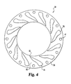
- Radial inflow swirler 30 includes the plurality of swirler vanes 36 and the plurality of fuel dispensers 41.
- the radial inflow swirler 30 includes twelve vanes 36 that are spaced equally around the circumference of the swirler and are connected between two end plates 56.
- swirlers having other quantities of vanes and spacing are contemplated herein.
- Vanes 36 are joined to the end plate 56 by commonly known assembly techniques such as brazing.
- the vane 36 is integrally formed with the end plate by machining.
- the vanes 36 are preferably inclined at an angle.
- the swirl angle of the fuel and air passing from the radial inflow swirler is defined as the tan -1 (azimuthal velocity/axial velocity) at the throat of the radial inflow swirler, which is defined at the radial inflow premixer discharge plane.
- the present invention has increased degrees of swirl and in a more preferred form of the present invention the swirl angle is within a range of about 40° to about 70°.
- the air and fuel flowing between the plurality of vanes 36 flows in channels 80 defined between the vanes and the end plates.
- Each of the vanes 36 include a leading edge 81, a trailing edge 82 and a surface extending in the streamwise and spanwise directions.
- the vanes are preferably constructed of alloyed steel which is capable of withstanding compressor dischage temperature levels.
- One form of the present invention contemplates stainless steel, but other materials are contemplated herein.
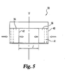
- FIG. 5 there is illustrated a schematic view of a portion of the radial inflow swirler 30.
- the schematic diagram illustrates the relationship between the radial inflow swirler inlet 40, the plurality of vanes 36, and the fuel dispensers 41.
- the fuel and air passes through the channels 80 defined between the plurality of vanes 36 and out of the system at outlet 42.
- the arrow "J" in Fig. 5 illustrates the cross-sectioanl area taken at the discharge of the radial inflow swirler.
- the term expansion ratio as utilized herein defines a ratio where the cross- sectional area of the internal volume of the combustion chamber is divided by the cross-sectional area taken at the discharge of the radial inflow swirler.
- the discharge plane is located at the throat of the dome quarl, which is the location of smallest diameter.
- the fuel dispenser 41 is defined by a tube having a plurality of fuel dispensing holes 60 that are located and oriented to create the desired fuel concentration profile across the radial inflow swirler. It is also understood that in an alternative embodiment of the present invention, the fuel dispenser 41 could be integrally formed with the plurality of vanes in the system.
- the present invention contemplates that the fuel dispensing holes 60 preferably have a size within a range of about 0.51mm (0.020 inches) to about 2.03mm (0.080 inches). Further, the fuel dispensing holes are laterally spaced between about 3.18mm (0.125 inches) and about 12.7mm (0.500 inches).
- the fuel dispensing holes 60 are oriented on an included angle that is preferably within a range of about 90 to about 180.
- the fuel dispensing holes 60 have a diameter of 1.07mm (0.042 inches), are spaced axially 6.35mm (0.250 inches) and are set at an included angle of 135.
- the included angle includes angle and angle C, and in the one form angles and angle are unequal.
- angle Q is about 79 and angle is about 56 . It is understood that the present invention contemplates other fuel dispensing hole sizes, spacing and angles of inclusion.
- twist mixer is positioned within the flow path of the primary tubular premixer and/or the secondary tubular premixer to mix the entire flow within each of their passageways to provide enhanced mixing.
- the enhanced mixing associated with the twist mixer is related to secondary flow mechanisms without flow recirculation that could lead to pre-ignition or flashback.
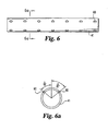
- the twist mixer 63 is formed from a sheet material and has a plurality of key openings 65 formed therein. Key openings 65 have a substantially circular portion 66 and a truncated triangular shape 67.
- the main body member 68 is then twisted about a longitudinal centerline Z through 180.
- the twisting is substantially uniform along the longitudinal axis Z.
- the main body member is a plate of about 0.76mm (0.030 inches) in thickness, about 73.7mm (2.9 inches) long and about 22.9mm (0.9 inches) wide.
- a main body member having other dimensions is contemplated herein.
- the present invention contemplates that each of the primary tubular premixers and/or the secondary tubular premixers can utilize a different type of mixing device.
- FIG. 8 there is illustrated an enlarged schematic representation of the fueling manifold/fuel dispenser 52 for delivering fuel to the primary tubular premixer 33.
- the fueling manifold/fuel dispenser 52 surrounds the tube 70 defining the body of the tubular premixer 33.
- Located around the circumference of the tube 70 is a plurality of fuel dispensing apertures 71 that receive fuel from the fueling manifold/fuel dispenser 52.
- the fuel dispensing apertures 71 are formed at a compound angle through the tube.
- the number of fuel dispensing apertures is preferably within a range of about 4 to about 8. However, other quantities of apertures and different angles of orientation are contemplated herein.
- the fueling manifold preferably delivers a fuel profile that is heavier between the wall and the center line.
- a substantially similar system is utilized in one embodiment of the present invention to deliver fuel to the secondary tubular premixers 34.
- the fueling manifold/fuel dispenser 54 surrounds the tube that defines the body of the secondary tubular premixer 34. Located around the circumference of the tube is a plurality of fuel dispensing discharge apertures that receive fuel from the fueling manifold/fuel dispenser 54.
- the flow exiting the swirl premixer will have a high ration of swirl velocity (azimuthal velocity) to axial velocity and hence a high swirl angle. Downstream of the throat the swirler/premixer the flow will begin to expand as it flows along the contour of the dome. The force created by the high swirl velocity produces this expansion. The flow will continue to expand until reaching the combustion liner cylinder. The flow will continue along the wall of th ecombustor liner until reaching the primary jets from the plurality of primary tubular premixers. In this region the swirler flow is forced inward and collapses into the volume just downstream of the centerbody and inside the swirler annulus flow. Thus a toroidal recirculation zone is produced downstream of the swirler exit and upstream of the primary jets. This recirculation zone is at a much lower velocity allowing stable combustion to exit in the zone.
- swirl velocity azimuthal velocity
- the fluid flows exiting the tubular premixers defines a tubular flow with a typical tube flow velocity profile.
- the jet flow will be oriented along the axis of the tubular premixer tube cross-section just upstream of the combustor liner.
- the flow velocity profile and jet flow orientation will be altered when turning vanes are used.
- the jet flow will enter the combustion liner and penetrate roughly one third of the radius. Further, a portion of the primary jet flow will be entrained in thetoroidal recirculation zone produced by the swirler while the remainder will simply mix with products downstream of the recirculation zone.
Landscapes
- Engineering & Computer Science (AREA)
- Chemical & Material Sciences (AREA)
- Combustion & Propulsion (AREA)
- Mechanical Engineering (AREA)
- General Engineering & Computer Science (AREA)
- Gas Burners (AREA)
Claims (29)
- Brûleur pour brûler un combustible et un mélange de gaz, comprenant:un carter mécanique (23);une chambre de combustion (22), agencée dans ledit carter mécanique (23) et comportant une première extrémité et une deuxième extrémité ainsi qu'un volume interne (21);une chambre de turbulence à flux radial (30), agencée au niveau de ladite première extrémité, en communication d'écoulement avec ledit volume interne (21), ladite chambre de turbulence à flux radial (30) englobant plusieurs premiers distributeurs de combustible (41), pour amener le combustible dans le gaz dans ladite chambre de turbulence (30), et plusieurs aubes (36) pour diriger l'écoulement de combustible et de gaz dans le volume interne (21), pour définir un écoulement à turbulence;ladite chambre de combustion (22) comportant une région de combustion primaire (47) et ladite chambre de turbulence à flux radial (30) amenant le combustible et le gaz dans ladite région de combustion primaire (47); etcaractérisé par plusieurs premiers dispositifs de prémélange tubulaires de combustible et de gaz à espacement circonférentiel (33), connectés à ladite chambre de combustion (22) et en communication d'écoulement avec ledit volume interne (21), chacun desdits plusieurs premiers dispositifs de prémélange tubulaires de combustible et de gaz (33) étant adapté pour amener un écoulement en jet prémélangé de gaz et de combustible dans ladite région de combustion primaire (47).
- Brûleur selon la revendication 1, dans lequel ladite chambre de combustion (22) est définie par une chemise de la chambre de combustion (90), chacun desdits plusieurs premiers dispositifs de prémélange tubulaires de combustible et de gaz (33) comportant un élément tubulaire avec un passage d'écoulement, et un deuxième distributeur de combustible (52) qui y est associé, chacun des deuxièmes distributeurs de combustible (52) étant adapté pour amener le combustible à travers plusieurs ouvertures dans ledit élément tubulaire.
- Brûleur selon l'une quelconque des revendications précédentes, dans lequel lesdits plusieurs premiers distributeurs de combustible (41) et lesdits plusieurs premiers dispositifs de prémélange tubulaires de combustible et de gaz (33) sont alimentés en combustible de manière indépendante les uns des autres.
- Brûleur selon l'une quelconque des revendications précédentes, englobant en outre plusieurs deuxièmes dispositifs de prémélange tubulaires de combustible et de gaz (34), connectés à ladite chambre de combustion (22) et en communication d'écoulement avec ledit volume interne (21); chacun desdits plusieurs deuxièmes dispositifs de prémélange tubulaires (34) amenant un écoulement en jet prémélangé de gaz et de combustible dans ledit volume interne (21);
ladite chambre de combustion (22) englobant une région de combustion primaire dans une première partie de ladite chambre de combustion (22) et une région de combustion secondaire (48) dans une deuxième partie de ladite chambre de combustion (22); et
lesdits plusieurs premiers dispositifs de prémélange tubulaires de combustible et de gaz (33) amenant le combustible et le gaz dans ladite région de combustion primaire (47), et lesdits plusieurs deuxièmes dispositifs de prémélange tubulaires (34) amenant le combustible et le gaz dans ladite région de combustion secondaire (48), ladite région de combustion secondaire (48) étant espacée axialement de ladite région de combustion primaire (47);
et dans lequel le gaz est de l'air. - Brûleur selon l'une quelconque des revendications précédentes, dans lequel ladite chambre de turbulence à flux radial (30) décharge un écoulement à turbulence de combustible et de gaz, lesdits plusieurs premiers dispositifs de prémélange tubulaires de combustible et de gaz (33) déchargeant plusieurs écoulements en jet de combustible et de gaz, représentant au moins 15% de l'écoulement à turbulence.
- Brûleur selon l'une quelconque des revendications précédentes, dans lequel chacun desdits plusieurs premiers dispositifs de prémélange tubulaires de combustible et de gaz (33) amène un jet de combustible et d'air s'écoulant dans une direction allant notablement vers l'intérieur.
- Brûleur selon l'une quelconque des revendications précédentes, englobant en outre un dôme (32) positionné au niveau de ladite première extrémité de la chambre de combustion (22) et s'étendant dans ledit volume interne (21), ledit dôme (32) comportant une surface externe (44) profilée de sorte à réduire au minimum la séparation de l'écoulement dudit écoulement de la chambre de turbulence de combustible et de gaz passant dans ledit volume interne (21).
- Brûleur selon la revendication 7, dans lequel ladite surface externe (44) a une forme géométrique définie sous forme d'un ouvreau.
- Brûleur selon la revendication 7 ou 8, dans lequel ladite surface externe (44) est formée sur une bague annulaire symétrique à un axe longitudinal.
- Brûleur selon l'une quelconque des revendications 7 à 9, dans lequel ledit dôme (32) englobe un élément de paroi annulaire (70) agencé dans ledit volume interne (21), ladite chambre de combustion (23) englobant une chemise de la chambre de combustion (90) définissant ledit volume interne (21), ledit élément de paroi annulaire (70) étant espacé de ladite chemise de la chambre de combustion (90).
- Brûleur selon l'une quelconque des revendications 7 à 10, englobant en premier lieu plusieurs premiers et deuxièmes dispositifs de prémélange tubulaires de combustible et de gaz (33, 34), en communication d'écoulement avec ledit volume interne (21), chacun desdits plusieurs premiers dispositifs de prémélange tubulaires de combustible et de gaz (33) comportant une première entrée (46) vers ladite chambre de combustion (22), et chacun desdits plusieurs deuxièmes dispositifs de prémélange tubulaires de combustible et de gaz (34) comportant une deuxième entrée (50) vers ladite chambre de combustion (22), ladite première entrée (46) étant décalée axialement par rapport à ladite deuxième entrée (50).
- Brûleur selon l'une quelconque des revendications 8 à 11, dans lequel ledit volume interne (21) est cylindrique, un rapport entre la surface de section transversale du volume interne (21) et la surface de section transversale définie par le diamètre le plus petit du dôme en ouvreau (32) étant supérieur ou égal à 2,75.
- Brûleur selon l'une quelconque des revendications 7 à 11, dans lequel ladite chambre de turbulence fait partie d'un dispositif de prémélange, et englobant en outre un corps central (35) positionné entre lesdites plusieurs aubes (36).
- Brûleur selon l'une quelconque des revendications 7 à 13, dans lequel ladite surface externe (44) a une section transversale convexe.
- Brûleur selon l'une quelconque des revendications 7 à 14, dans lequel ledit dôme (32) est symétrique à une ligne médiane longitudinale et s'étend axialement dans une partie dudit volume interne (21).
- Brûleur selon l'une quelconque des revendications 13 à 15, dans lequel ledit corps central (35) est espacé d'une partie dudit dôme (32) et s'étend le long de celle-ci.
- Brûleur selon la revendication 1, dans lequel :ladite chambre de combustion (22) est cylindrique et comporte une partie avec une surface de section transversale constante, ladite chambre de combustion (22) comportant plusieurs premières ouvertures (75) dans ladite partie, et plusieurs deuxièmes ouvertures (50) dans ladite partie, lesdites plusieurs premières ouvertures (75) étant espacées axialement desdites plusieurs deuxièmes ouvertures (50);chacun desdits plusieurs premiers dispositifs de prémélange tubulaires de combustible et de gaz (33) étant en communication d'écoulement avec une desdites plusieurs premières ouvertures (75); etcomprenant en outre plusieurs deuxièmes dispositifs de prémélange tubulaires de combustible et de gaz (34), accouplés à ladite chambre de combustion (22), chacun desdits plusieurs deuxièmes dispositifs de prémélange tubulaires de combustible et de gaz (34) étant en communication d'écoulement avec une desdites plusieurs deuxièmes ouvertures (50).
- Brûleur selon la revendication 17, dans lequel chacun desdits premiers dispositifs de prémélange de combustible et de gaz (33) englobe un élément tubulaire contenant une trajectoire d'écoulement de fluide, et englobant en outre un mélangeur d'écoulement mécanique (63) dans ladite trajectoire d'écoulement.
- Brûleur selon l'une la revendication 18, dans lequel chacun desdits plusieurs deuxièmes dispositifs de prémélange tubulaires de combustible et de gaz (34) englobe un élément tubulaire, contenant une trajectoire d'écoulement, et englobant en outre un mélangeur d'écoulement mécanique (63) dans ladite trajectoire d'écoulement.
- Brûleur selon l'une quelconque des revendications 17 à 19, dans lequel ladite chambre de combustion cylindrique (22) est définie par une chemise de la chambre de combustion (90), et englobant en outre une premier collecteur d'alimentation en combustible (52), adapté pour amener le combustible vers lesdits plusieurs premiers dispositifs de prémélange tubulaires de combustible et de gaz (32), et un deuxième collecteur d'alimentation en combustible (54), adapté pour amener le combustible vers lesdits plusieurs deuxièmes dispositifs de prémélange tubulaires de combustible et de gaz (34), lesdits plusieurs premiers dispositifs de prémélange tubulaires de combustible et de gaz (33) et lesdits plusieurs deuxièmes dispositifs de prémélange tubulaires de combustible et de gaz (34) étant indépendants les uns des autres.
- Brûleur selon l'une quelconque des revendications 17 à 20, dans lequel ledit volume interne (21) comporte une région de combustion primaire (47) et une région de combustion secondaire (48), espacée axialement de ladite région de combustion primaire (47), lesdites plusieurs premières ouvertures (75) étant formées dans ladite partie dans une première région associée à ladite première région de combustion (43) et lesdites plusieurs deuxièmes ouvertures (50) étant formées dans ladite partie dans une deuxième région associée à ladite région de combustion secondaire (48).
- Brûleur selon l'une quelconque des revendications 17 à 21, dans lequel lesdits plusieurs premiers dispositifs de prémélange tubulaires de combustible et de gaz (33) et lesdits plusieurs deuxièmes dispositifs de prémélange tubulaires de combustible et de gaz (34) englobent au moins une aube de rotation de décharge pour faire tourner un écoulement de combustible et d'air passant dans ledit volume interne (21).
- Brûleur selon l'une quelconque des revendications 4, 11, et 23 à 22, lorsqu'elles ne dépendent pas de la revendication 2, dans lequel au moins un desdits plusieurs premiers et deuxièmes dispositifs de prémélange (33, 34) comprend:un élément tubulaire, comportant une première extrémité et une deuxième extrémité et un passage d'écoulement entre elles;un collecteur d'alimentation en combustible (52, 54), en communication de fluide avec ledit passage d'écoulement pour amener un combustible dans ledit passage d'écoulement; etun moyen de mélange tournant (63) pour faire tourner le fluide s'écoulant dans ledit passage d'écoulement, ledit moyen de mélange tournant (63) étant positionné dans ledit passage d'écoulement.
- Brûleur selon la revendication 23, dans lequel ladite première extrémité du passage tubulaire est une entrée (45, 49), adaptée pour recevoir un écoulement de gaz, ladite deuxième extrémité (46, 50) étant une sortie adaptée pour décharger un écoulement de gaz et de combustible, ledit élément tubulaire englobant plusieurs ouvertures pour permettre le passage du combustible dudit collecteur d'alimentation de combustible (52, 54) dans ledit passage d'écoulement.
- Brûleur selon la revendication 24, dans lequel lesdites plusieurs ouvertures sont espacées autour de la circonférence dudit élément tubulaire.
- Brûleur selon l'une quelconque des revendications 23 à 25, dans lequel ledit mélangeur tournant (63) est agencé dans ledit passage d'écoulement en aval dudit collecteur d'alimentation en combustible (52, 54), ledit mélangeur tournant (63) englobant une élément de plaque (68) torsadé autour d'un axe longitudinal.
- Brûleur selon la revendication 26, dans lequel ledit élément de plaque (68) englobe une première extrémité et une deuxième extrémité, ladite deuxième extrémité étant tournée d'environ 180 degrés par rapport à ladite première extrémité.
- Brûleur selon l'une quelconque des revendications précédentes, dans lequel ledit écoulement à turbulence se fait uniquement dans un sens, dans le sens des aiguilles d'une montre ou dans le sens contraire des aiguilles d'une montre.
- Brûleur selon l'une quelconque des revendications 1, 3 à 19, lorsqu'elles ne dépendent pas de la revendication 2, englobant en outre plusieurs deuxièmes distributeurs de combustible (52), chacun desdits plusieurs premiers dispositif de prémélange tubulaires de combustible et de gaz (33) englobant un premier passage d'écoulement de fluide, en communication d'écoulement avec un desdits deuxièmes distributeurs de combustible (52), lesdits deuxièmes distributeurs de combustible (52) n'obstruant pas lesdits premiers passages d'écoulement.
Priority Applications (1)
| Application Number | Priority Date | Filing Date | Title |
|---|---|---|---|
| EP10014578.8A EP2357413B1 (fr) | 2002-03-12 | 2003-03-06 | Système de combustion sèche à faibles émissions de NOx comprenant des moyens permettant d'éliminer les bruits de combustion |
Applications Claiming Priority (3)
| Application Number | Priority Date | Filing Date | Title |
|---|---|---|---|
| US96230 | 2002-03-12 | ||
| US10/096,230 US6691515B2 (en) | 2002-03-12 | 2002-03-12 | Dry low combustion system with means for eliminating combustion noise |
| PCT/US2003/006933 WO2003078814A1 (fr) | 2002-03-12 | 2003-03-06 | Systeme de combustion faible a sec dote d'un moyen permettant d'eliminer le bruit de combustion |
Related Child Applications (2)
| Application Number | Title | Priority Date | Filing Date |
|---|---|---|---|
| EP10014578.8A Division EP2357413B1 (fr) | 2002-03-12 | 2003-03-06 | Système de combustion sèche à faibles émissions de NOx comprenant des moyens permettant d'éliminer les bruits de combustion |
| EP10014578.8 Division-Into | 2010-11-12 |
Publications (3)
| Publication Number | Publication Date |
|---|---|
| EP1488086A1 EP1488086A1 (fr) | 2004-12-22 |
| EP1488086A4 EP1488086A4 (fr) | 2007-07-04 |
| EP1488086B1 true EP1488086B1 (fr) | 2012-11-28 |
Family
ID=28038990
Family Applications (2)
| Application Number | Title | Priority Date | Filing Date |
|---|---|---|---|
| EP03711450A Expired - Lifetime EP1488086B1 (fr) | 2002-03-12 | 2003-03-06 | Systeme de combustion faible a sec dote d'un moyen permettant d'eliminer le bruit de combustion |
| EP10014578.8A Expired - Lifetime EP2357413B1 (fr) | 2002-03-12 | 2003-03-06 | Système de combustion sèche à faibles émissions de NOx comprenant des moyens permettant d'éliminer les bruits de combustion |
Family Applications After (1)
| Application Number | Title | Priority Date | Filing Date |
|---|---|---|---|
| EP10014578.8A Expired - Lifetime EP2357413B1 (fr) | 2002-03-12 | 2003-03-06 | Système de combustion sèche à faibles émissions de NOx comprenant des moyens permettant d'éliminer les bruits de combustion |
Country Status (4)
| Country | Link |
|---|---|
| US (1) | US6691515B2 (fr) |
| EP (2) | EP1488086B1 (fr) |
| AU (1) | AU2003213759A1 (fr) |
| WO (1) | WO2003078814A1 (fr) |
Cited By (2)
| Publication number | Priority date | Publication date | Assignee | Title |
|---|---|---|---|---|
| US11525579B2 (en) | 2020-07-06 | 2022-12-13 | Doosan Enerbility Co., Ltd. | Combustor nozzle, combustor, and gas turbine including same |
| US11815026B2 (en) | 2020-07-06 | 2023-11-14 | Doosan Enerbility Co., Ltd. | Combustor nozzle, and combustor and gas turbine including the same |
Families Citing this family (36)
| Publication number | Priority date | Publication date | Assignee | Title |
|---|---|---|---|---|
| GB0230070D0 (en) * | 2002-12-23 | 2003-01-29 | Bowman Power Systems Ltd | A combustion device |
| US20050106520A1 (en) * | 2003-09-05 | 2005-05-19 | Michael Cornwell | Device for stabilizing combustion in gas turbine engines |
| US7308793B2 (en) * | 2005-01-07 | 2007-12-18 | Power Systems Mfg., Llc | Apparatus and method for reducing carbon monoxide emissions |
| GB2435508B (en) * | 2006-02-22 | 2011-08-03 | Siemens Ag | A swirler for use in a burner of a gas turbine engine |
| US7716931B2 (en) * | 2006-03-01 | 2010-05-18 | General Electric Company | Method and apparatus for assembling gas turbine engine |
| ITTO20070193A1 (it) * | 2007-03-14 | 2008-09-15 | Ansaldo Ricerche S P A | Bruciatore premix di una turbina a gas, in particolare per una microturbina |
| EP1985924A1 (fr) * | 2007-04-23 | 2008-10-29 | Siemens Aktiengesellschaft | Dispositif de tourbillonnement |
| EP2116768B1 (fr) * | 2008-05-09 | 2016-07-27 | Alstom Technology Ltd | Brûleur |
| JP5172468B2 (ja) * | 2008-05-23 | 2013-03-27 | 川崎重工業株式会社 | 燃焼装置および燃焼装置の制御方法 |
| US8176739B2 (en) * | 2008-07-17 | 2012-05-15 | General Electric Company | Coanda injection system for axially staged low emission combustors |
| US8220270B2 (en) * | 2008-10-31 | 2012-07-17 | General Electric Company | Method and apparatus for affecting a recirculation zone in a cross flow |
| US20100192577A1 (en) * | 2009-02-02 | 2010-08-05 | General Electric Company | System and method for reducing combustion dynamics in a turbomachine |
| US20100192582A1 (en) | 2009-02-04 | 2010-08-05 | Robert Bland | Combustor nozzle |
| US8511089B2 (en) * | 2009-07-31 | 2013-08-20 | Rolls-Royce Corporation | Relief slot for combustion liner |
| DE102009054669A1 (de) * | 2009-12-15 | 2011-06-16 | Man Diesel & Turbo Se | Brenner für eine Turbine |
| GB2489963B (en) * | 2011-04-13 | 2015-11-04 | Rolls Royce Plc | Fuel injector arrangement having an igniter |
| WO2013002664A1 (fr) * | 2011-06-28 | 2013-01-03 | General Electric Company | Injection pauvre retardée rationnelle |
| US8850821B2 (en) | 2011-10-07 | 2014-10-07 | General Electric Company | System for fuel injection in a fuel nozzle |
| US20130276450A1 (en) * | 2012-04-24 | 2013-10-24 | General Electric Company | Combustor apparatus for stoichiometric combustion |
| RU2604628C2 (ru) * | 2012-09-17 | 2016-12-10 | НОВ КОНДОР ЭлЭлСи | Способ и устройство смесителя |
| US20150167980A1 (en) * | 2013-12-18 | 2015-06-18 | Jared M. Pent | Axial stage injection dual frequency resonator for a combustor of a gas turbine engine |
| US9869190B2 (en) | 2014-05-30 | 2018-01-16 | General Electric Company | Variable-pitch rotor with remote counterweights |
| US10072510B2 (en) | 2014-11-21 | 2018-09-11 | General Electric Company | Variable pitch fan for gas turbine engine and method of assembling the same |
| US10100653B2 (en) | 2015-10-08 | 2018-10-16 | General Electric Company | Variable pitch fan blade retention system |
| US11174792B2 (en) | 2019-05-21 | 2021-11-16 | General Electric Company | System and method for high frequency acoustic dampers with baffles |
| US11156164B2 (en) | 2019-05-21 | 2021-10-26 | General Electric Company | System and method for high frequency accoustic dampers with caps |
| GB2593123A (en) * | 2019-06-25 | 2021-09-22 | Siemens Ag | Combustor for a gas turbine |
| JP7646441B2 (ja) * | 2021-04-30 | 2025-03-17 | 東芝エネルギーシステムズ株式会社 | ガスタービン燃焼器構造体 |
| US11525403B2 (en) * | 2021-05-05 | 2022-12-13 | Pratt & Whitney Canada Corp. | Fuel nozzle with integrated metering and flashback system |
| US11674435B2 (en) | 2021-06-29 | 2023-06-13 | General Electric Company | Levered counterweight feathering system |
| US11795964B2 (en) | 2021-07-16 | 2023-10-24 | General Electric Company | Levered counterweight feathering system |
| KR102583222B1 (ko) * | 2022-01-06 | 2023-09-25 | 두산에너빌리티 주식회사 | 연소기용 노즐, 연소기 및 이를 포함하는 가스 터빈 |
| US12339002B2 (en) | 2022-04-29 | 2025-06-24 | General Electric Company | Propulsion system for jet noise reduction |
| US12601271B2 (en) | 2022-10-21 | 2026-04-14 | General Electric Company | Variable pitch fan of a gas turbine engine |
| US12078350B2 (en) * | 2022-11-10 | 2024-09-03 | General Electric Company | Gas turbine combustion section having an integrated fuel cell assembly |
| CN116221780B (zh) * | 2023-03-22 | 2024-05-03 | 中国科学院工程热物理研究所 | 掺混机构及燃烧装置 |
Family Cites Families (33)
| Publication number | Priority date | Publication date | Assignee | Title |
|---|---|---|---|---|
| US3779695A (en) * | 1970-10-30 | 1973-12-18 | United Aircraft Corp | Combustion chamber for gas dynamic laser |
| US4013395A (en) * | 1971-05-11 | 1977-03-22 | Wingaersheek, Inc. | Aerodynamic fuel combustor |
| US4796429A (en) | 1976-11-15 | 1989-01-10 | General Motors Corporation | Combustor diffuser |
| US4263780A (en) * | 1979-09-28 | 1981-04-28 | General Motors Corporation | Lean prechamber outflow combustor with sets of primary air entrances |
| US4399652A (en) | 1981-03-30 | 1983-08-23 | Curtiss-Wright Corporation | Low BTU gas combustor |
| US4872833A (en) * | 1988-05-16 | 1989-10-10 | A. O. Smith Corporation | Gas burner construction |
| US4928481A (en) * | 1988-07-13 | 1990-05-29 | Prutech Ii | Staged low NOx premix gas turbine combustor |
| GB9023004D0 (en) | 1990-10-23 | 1990-12-05 | Rolls Royce Plc | A gas turbine engine combustion chamber and a method of operating a gas turbine engine combustion chamber |
| EP0534685A1 (fr) | 1991-09-23 | 1993-03-31 | General Electric Company | Brûleur à prémélange avec faible production de NOx |
| US5289686A (en) | 1992-11-12 | 1994-03-01 | General Motors Corporation | Low nox gas turbine combustor liner with elliptical apertures for air swirling |
| CA2124069A1 (fr) | 1993-05-24 | 1994-11-25 | Boris M. Kramnik | Chambre de combustion de turbine a gaz a geometrie invariable, a faible niveau de pollution |
| JP3335713B2 (ja) * | 1993-06-28 | 2002-10-21 | 株式会社東芝 | ガスタービン燃焼器 |
| US5628182A (en) | 1993-07-07 | 1997-05-13 | Mowill; R. Jan | Star combustor with dilution ports in can portions |
| US5394688A (en) | 1993-10-27 | 1995-03-07 | Westinghouse Electric Corporation | Gas turbine combustor swirl vane arrangement |
| US5408825A (en) | 1993-12-03 | 1995-04-25 | Westinghouse Electric Corporation | Dual fuel gas turbine combustor |
| US5387081A (en) | 1993-12-09 | 1995-02-07 | Pratt & Whitney Canada, Inc. | Compressor diffuser |
| GB2284884B (en) | 1993-12-16 | 1997-12-10 | Rolls Royce Plc | A gas turbine engine combustion chamber |
| JP2950720B2 (ja) * | 1994-02-24 | 1999-09-20 | 株式会社東芝 | ガスタービン燃焼装置およびその燃焼制御方法 |
| FR2717250B1 (fr) * | 1994-03-10 | 1996-04-12 | Snecma | Système d'injection à prémélange. |
| GB9410233D0 (en) * | 1994-05-21 | 1994-07-06 | Rolls Royce Plc | A gas turbine engine combustion chamber |
| CA2194911C (fr) | 1994-07-13 | 2004-11-16 | Anders Sjunnesson | Chambre de combustion a faibles emissions destinee a des moteurs a turbine a gaz |
| US5657632A (en) | 1994-11-10 | 1997-08-19 | Westinghouse Electric Corporation | Dual fuel gas turbine combustor |
| US5836164A (en) * | 1995-01-30 | 1998-11-17 | Hitachi, Ltd. | Gas turbine combustor |
| GB2299399A (en) | 1995-03-25 | 1996-10-02 | Rolls Royce Plc | Variable geometry air-fuel injector |
| US5813232A (en) | 1995-06-05 | 1998-09-29 | Allison Engine Company, Inc. | Dry low emission combustor for gas turbine engines |
| EP0747635B1 (fr) | 1995-06-05 | 2003-01-15 | Rolls-Royce Corporation | Brûleur à prémélange pauvre avec faible production de NOx pour turbines à gaz industrielles |
| US5647215A (en) | 1995-11-07 | 1997-07-15 | Westinghouse Electric Corporation | Gas turbine combustor with turbulence enhanced mixing fuel injectors |
| US5987889A (en) | 1997-10-09 | 1999-11-23 | United Technologies Corporation | Fuel injector for producing outer shear layer flame for combustion |
| US6109038A (en) * | 1998-01-21 | 2000-08-29 | Siemens Westinghouse Power Corporation | Combustor with two stage primary fuel assembly |
| GB2337102A (en) | 1998-05-09 | 1999-11-10 | Europ Gas Turbines Ltd | Gas-turbine engine combustor |
| US6289676B1 (en) | 1998-06-26 | 2001-09-18 | Pratt & Whitney Canada Corp. | Simplex and duplex injector having primary and secondary annular lud channels and primary and secondary lud nozzles |
| GB9929601D0 (en) * | 1999-12-16 | 2000-02-09 | Rolls Royce Plc | A combustion chamber |
| FR2827367B1 (fr) * | 2001-07-16 | 2003-10-17 | Snecma Moteurs | Systeme d'injection aeromecanique a vrille primaire anti-retour |
-
2002
- 2002-03-12 US US10/096,230 patent/US6691515B2/en not_active Expired - Lifetime
-
2003
- 2003-03-06 AU AU2003213759A patent/AU2003213759A1/en not_active Abandoned
- 2003-03-06 EP EP03711450A patent/EP1488086B1/fr not_active Expired - Lifetime
- 2003-03-06 EP EP10014578.8A patent/EP2357413B1/fr not_active Expired - Lifetime
- 2003-03-06 WO PCT/US2003/006933 patent/WO2003078814A1/fr not_active Ceased
Cited By (2)
| Publication number | Priority date | Publication date | Assignee | Title |
|---|---|---|---|---|
| US11525579B2 (en) | 2020-07-06 | 2022-12-13 | Doosan Enerbility Co., Ltd. | Combustor nozzle, combustor, and gas turbine including same |
| US11815026B2 (en) | 2020-07-06 | 2023-11-14 | Doosan Enerbility Co., Ltd. | Combustor nozzle, and combustor and gas turbine including the same |
Also Published As
| Publication number | Publication date |
|---|---|
| AU2003213759A1 (en) | 2003-09-29 |
| US6691515B2 (en) | 2004-02-17 |
| US20030172655A1 (en) | 2003-09-18 |
| EP1488086A4 (fr) | 2007-07-04 |
| WO2003078814A1 (fr) | 2003-09-25 |
| EP2357413A1 (fr) | 2011-08-17 |
| EP1488086A1 (fr) | 2004-12-22 |
| EP2357413B1 (fr) | 2017-05-03 |
Similar Documents
| Publication | Publication Date | Title |
|---|---|---|
| EP1488086B1 (fr) | Systeme de combustion faible a sec dote d'un moyen permettant d'eliminer le bruit de combustion | |
| EP1499800B1 (fr) | Module de premelange de combustible pour chambre de combustion de turbine a gaz | |
| CA2137593C (fr) | Chambre de combustion | |
| US7757491B2 (en) | Fuel nozzle for a gas turbine engine and method for fabricating the same | |
| US5407347A (en) | Apparatus and method for reducing NOx, CO and hydrocarbon emissions when burning gaseous fuels | |
| US10480791B2 (en) | Fuel injector to facilitate reduced NOx emissions in a combustor system | |
| US7908863B2 (en) | Fuel nozzle for a gas turbine engine and method for fabricating the same | |
| JP4922878B2 (ja) | ガスタービン燃焼器 | |
| EP1985926A2 (fr) | Équipement de combustion et procédé de combustion | |
| US6845621B2 (en) | Annular combustor for use with an energy system | |
| JPH10148334A (ja) | ガスタービンエンジンの二重燃料噴射器の液体パイロット燃料噴射方法と装置 | |
| CN115289473B (zh) | 气粉双燃料燃烧器 | |
| US8881531B2 (en) | Gas turbine engine premix injectors | |
| US8596074B2 (en) | Gas turbine combustor | |
| EP3425281B1 (fr) | Buse pilote dotée de prémélange en ligne | |
| CN115451433A (zh) | 一种用于燃气轮机燃烧室的燃料喷嘴预混系统 | |
| EP4187154A1 (fr) | Buse à combustible avec passage d'air à noyau restreint | |
| CA2167320C (fr) | Appareil et methode de reduction des emissions de nox, de co et d'hydrocarbures lors de la combustion de gaz | |
| US20240353097A1 (en) | Swirl burner for ammonia combustion | |
| CN1187581A (zh) | 双流切向进入式喷嘴 | |
| EP1921376A1 (fr) | Sistème d'injection de carburant | |
| EP4675176A1 (fr) | Moteur à turbine avec injecteur de carburant | |
| CN121520592A (zh) | 一种带有含氢燃料燃烧喷嘴的煤粉燃烧器 |
Legal Events
| Date | Code | Title | Description |
|---|---|---|---|
| PUAI | Public reference made under article 153(3) epc to a published international application that has entered the european phase |
Free format text: ORIGINAL CODE: 0009012 |
|
| 17P | Request for examination filed |
Effective date: 20041011 |
|
| AK | Designated contracting states |
Kind code of ref document: A1 Designated state(s): AT BE BG CH CY CZ DE DK EE ES FI FR GB GR HU IE IT LI LU MC NL PT RO SE SI SK TR |
|
| AX | Request for extension of the european patent |
Extension state: AL LT LV MK |
|
| RIN1 | Information on inventor provided before grant (corrected) |
Inventor name: RAZDAN, MOHAN, K. Inventor name: SMITH, DUANE Inventor name: VERDOUW, ALBERT, J. Inventor name: MCCORMICK, KEITH |
|
| RBV | Designated contracting states (corrected) |
Designated state(s): DE FR GB |
|
| A4 | Supplementary search report drawn up and despatched |
Effective date: 20070601 |
|
| RIC1 | Information provided on ipc code assigned before grant |
Ipc: F23R 3/28 20060101AFI20070525BHEP Ipc: F23R 3/12 20060101ALI20070525BHEP Ipc: F23R 3/34 20060101ALI20070525BHEP Ipc: F23R 3/44 20060101ALI20070525BHEP Ipc: F23D 14/82 20060101ALI20070525BHEP |
|
| 17Q | First examination report despatched |
Effective date: 20081104 |
|
| GRAP | Despatch of communication of intention to grant a patent |
Free format text: ORIGINAL CODE: EPIDOSNIGR1 |
|
| GRAS | Grant fee paid |
Free format text: ORIGINAL CODE: EPIDOSNIGR3 |
|
| GRAA | (expected) grant |
Free format text: ORIGINAL CODE: 0009210 |
|
| AK | Designated contracting states |
Kind code of ref document: B1 Designated state(s): DE FR GB |
|
| REG | Reference to a national code |
Ref country code: GB Ref legal event code: FG4D |
|
| REG | Reference to a national code |
Ref country code: DE Ref legal event code: R096 Ref document number: 60342700 Country of ref document: DE Effective date: 20130124 |
|
| PLBE | No opposition filed within time limit |
Free format text: ORIGINAL CODE: 0009261 |
|
| STAA | Information on the status of an ep patent application or granted ep patent |
Free format text: STATUS: NO OPPOSITION FILED WITHIN TIME LIMIT |
|
| 26N | No opposition filed |
Effective date: 20130829 |
|
| REG | Reference to a national code |
Ref country code: DE Ref legal event code: R097 Ref document number: 60342700 Country of ref document: DE Effective date: 20130829 |
|
| REG | Reference to a national code |
Ref country code: FR Ref legal event code: PLFP Year of fee payment: 14 |
|
| REG | Reference to a national code |
Ref country code: FR Ref legal event code: PLFP Year of fee payment: 15 |
|
| REG | Reference to a national code |
Ref country code: FR Ref legal event code: PLFP Year of fee payment: 16 |
|
| PGFP | Annual fee paid to national office [announced via postgrant information from national office to epo] |
Ref country code: DE Payment date: 20200327 Year of fee payment: 18 Ref country code: GB Payment date: 20200327 Year of fee payment: 18 |
|
| PGFP | Annual fee paid to national office [announced via postgrant information from national office to epo] |
Ref country code: FR Payment date: 20200325 Year of fee payment: 18 |
|
| REG | Reference to a national code |
Ref country code: DE Ref legal event code: R119 Ref document number: 60342700 Country of ref document: DE |
|
| GBPC | Gb: european patent ceased through non-payment of renewal fee |
Effective date: 20210306 |
|
| PG25 | Lapsed in a contracting state [announced via postgrant information from national office to epo] |
Ref country code: DE Free format text: LAPSE BECAUSE OF NON-PAYMENT OF DUE FEES Effective date: 20211001 Ref country code: GB Free format text: LAPSE BECAUSE OF NON-PAYMENT OF DUE FEES Effective date: 20210306 Ref country code: FR Free format text: LAPSE BECAUSE OF NON-PAYMENT OF DUE FEES Effective date: 20210331 |