EP1488904B1 - Dispositif de commande de moule et canal chaud monté sur le plateau porte-moule - Google Patents
Dispositif de commande de moule et canal chaud monté sur le plateau porte-moule Download PDFInfo
- Publication number
- EP1488904B1 EP1488904B1 EP04014495A EP04014495A EP1488904B1 EP 1488904 B1 EP1488904 B1 EP 1488904B1 EP 04014495 A EP04014495 A EP 04014495A EP 04014495 A EP04014495 A EP 04014495A EP 1488904 B1 EP1488904 B1 EP 1488904B1
- Authority
- EP
- European Patent Office
- Prior art keywords
- mold
- injection molding
- control module
- machine
- injection
- Prior art date
- Legal status (The legal status is an assumption and is not a legal conclusion. Google has not performed a legal analysis and makes no representation as to the accuracy of the status listed.)
- Expired - Lifetime
Links
- 238000001746 injection moulding Methods 0.000 claims description 52
- 238000002347 injection Methods 0.000 claims description 27
- 239000007924 injection Substances 0.000 claims description 27
- 238000012545 processing Methods 0.000 claims description 18
- 238000004891 communication Methods 0.000 claims description 12
- 238000000034 method Methods 0.000 description 11
- 239000000155 melt Substances 0.000 description 7
- 230000006870 function Effects 0.000 description 5
- 238000012544 monitoring process Methods 0.000 description 4
- 230000008569 process Effects 0.000 description 4
- 230000002411 adverse Effects 0.000 description 3
- 238000010586 diagram Methods 0.000 description 2
- 230000000694 effects Effects 0.000 description 2
- 238000005516 engineering process Methods 0.000 description 2
- 239000000463 material Substances 0.000 description 2
- 238000000465 moulding Methods 0.000 description 2
- 230000004044 response Effects 0.000 description 2
- 230000005540 biological transmission Effects 0.000 description 1
- 238000009529 body temperature measurement Methods 0.000 description 1
- 239000002826 coolant Substances 0.000 description 1
- 238000001816 cooling Methods 0.000 description 1
- 230000003247 decreasing effect Effects 0.000 description 1
- 239000000835 fiber Substances 0.000 description 1
- 238000010438 heat treatment Methods 0.000 description 1
- 230000002452 interceptive effect Effects 0.000 description 1
- 238000004519 manufacturing process Methods 0.000 description 1
- 230000007246 mechanism Effects 0.000 description 1
- 229910052751 metal Inorganic materials 0.000 description 1
- 239000002184 metal Substances 0.000 description 1
- 150000002739 metals Chemical class 0.000 description 1
- 230000000704 physical effect Effects 0.000 description 1
- 239000000843 powder Substances 0.000 description 1
- 238000004886 process control Methods 0.000 description 1
- 239000011347 resin Substances 0.000 description 1
- 229920005989 resin Polymers 0.000 description 1
- 238000000926 separation method Methods 0.000 description 1
- 238000012360 testing method Methods 0.000 description 1
Images





Classifications
-
- B—PERFORMING OPERATIONS; TRANSPORTING
- B22—CASTING; POWDER METALLURGY
- B22D—CASTING OF METALS; CASTING OF OTHER SUBSTANCES BY THE SAME PROCESSES OR DEVICES
- B22D17/00—Pressure die casting or injection die casting, i.e. casting in which the metal is forced into a mould under high pressure
- B22D17/20—Accessories: Details
- B22D17/32—Controlling equipment
-
- B—PERFORMING OPERATIONS; TRANSPORTING
- B29—WORKING OF PLASTICS; WORKING OF SUBSTANCES IN A PLASTIC STATE IN GENERAL
- B29C—SHAPING OR JOINING OF PLASTICS; SHAPING OF MATERIAL IN A PLASTIC STATE, NOT OTHERWISE PROVIDED FOR; AFTER-TREATMENT OF THE SHAPED PRODUCTS, e.g. REPAIRING
- B29C45/00—Injection moulding, i.e. forcing the required volume of moulding material through a nozzle into a closed mould; Apparatus therefor
- B29C45/17—Component parts, details or accessories; Auxiliary operations
- B29C45/1774—Display units or mountings therefor; Switch cabinets
-
- B—PERFORMING OPERATIONS; TRANSPORTING
- B29—WORKING OF PLASTICS; WORKING OF SUBSTANCES IN A PLASTIC STATE IN GENERAL
- B29C—SHAPING OR JOINING OF PLASTICS; SHAPING OF MATERIAL IN A PLASTIC STATE, NOT OTHERWISE PROVIDED FOR; AFTER-TREATMENT OF THE SHAPED PRODUCTS, e.g. REPAIRING
- B29C45/00—Injection moulding, i.e. forcing the required volume of moulding material through a nozzle into a closed mould; Apparatus therefor
- B29C45/17—Component parts, details or accessories; Auxiliary operations
- B29C45/76—Measuring, controlling or regulating
-
- B—PERFORMING OPERATIONS; TRANSPORTING
- B29—WORKING OF PLASTICS; WORKING OF SUBSTANCES IN A PLASTIC STATE IN GENERAL
- B29C—SHAPING OR JOINING OF PLASTICS; SHAPING OF MATERIAL IN A PLASTIC STATE, NOT OTHERWISE PROVIDED FOR; AFTER-TREATMENT OF THE SHAPED PRODUCTS, e.g. REPAIRING
- B29C45/00—Injection moulding, i.e. forcing the required volume of moulding material through a nozzle into a closed mould; Apparatus therefor
- B29C45/17—Component parts, details or accessories; Auxiliary operations
- B29C45/26—Moulds
- B29C45/27—Sprue channels ; Runner channels or runner nozzles
- B29C45/28—Closure devices therefor
- B29C45/2806—Closure devices therefor consisting of needle valve systems
- B29C2045/2865—Closure devices therefor consisting of needle valve systems having position detecting means
-
- B—PERFORMING OPERATIONS; TRANSPORTING
- B29—WORKING OF PLASTICS; WORKING OF SUBSTANCES IN A PLASTIC STATE IN GENERAL
- B29C—SHAPING OR JOINING OF PLASTICS; SHAPING OF MATERIAL IN A PLASTIC STATE, NOT OTHERWISE PROVIDED FOR; AFTER-TREATMENT OF THE SHAPED PRODUCTS, e.g. REPAIRING
- B29C2945/00—Indexing scheme relating to injection moulding, i.e. forcing the required volume of moulding material through a nozzle into a closed mould
- B29C2945/76—Measuring, controlling or regulating
- B29C2945/76003—Measured parameter
- B29C2945/76006—Pressure
-
- B—PERFORMING OPERATIONS; TRANSPORTING
- B29—WORKING OF PLASTICS; WORKING OF SUBSTANCES IN A PLASTIC STATE IN GENERAL
- B29C—SHAPING OR JOINING OF PLASTICS; SHAPING OF MATERIAL IN A PLASTIC STATE, NOT OTHERWISE PROVIDED FOR; AFTER-TREATMENT OF THE SHAPED PRODUCTS, e.g. REPAIRING
- B29C2945/00—Indexing scheme relating to injection moulding, i.e. forcing the required volume of moulding material through a nozzle into a closed mould
- B29C2945/76—Measuring, controlling or regulating
- B29C2945/76003—Measured parameter
- B29C2945/7604—Temperature
-
- B—PERFORMING OPERATIONS; TRANSPORTING
- B29—WORKING OF PLASTICS; WORKING OF SUBSTANCES IN A PLASTIC STATE IN GENERAL
- B29C—SHAPING OR JOINING OF PLASTICS; SHAPING OF MATERIAL IN A PLASTIC STATE, NOT OTHERWISE PROVIDED FOR; AFTER-TREATMENT OF THE SHAPED PRODUCTS, e.g. REPAIRING
- B29C2945/00—Indexing scheme relating to injection moulding, i.e. forcing the required volume of moulding material through a nozzle into a closed mould
- B29C2945/76—Measuring, controlling or regulating
- B29C2945/76003—Measured parameter
- B29C2945/76083—Position
-
- B—PERFORMING OPERATIONS; TRANSPORTING
- B29—WORKING OF PLASTICS; WORKING OF SUBSTANCES IN A PLASTIC STATE IN GENERAL
- B29C—SHAPING OR JOINING OF PLASTICS; SHAPING OF MATERIAL IN A PLASTIC STATE, NOT OTHERWISE PROVIDED FOR; AFTER-TREATMENT OF THE SHAPED PRODUCTS, e.g. REPAIRING
- B29C2945/00—Indexing scheme relating to injection moulding, i.e. forcing the required volume of moulding material through a nozzle into a closed mould
- B29C2945/76—Measuring, controlling or regulating
- B29C2945/76177—Location of measurement
- B29C2945/7618—Injection unit
- B29C2945/7621—Injection unit nozzle
-
- B—PERFORMING OPERATIONS; TRANSPORTING
- B29—WORKING OF PLASTICS; WORKING OF SUBSTANCES IN A PLASTIC STATE IN GENERAL
- B29C—SHAPING OR JOINING OF PLASTICS; SHAPING OF MATERIAL IN A PLASTIC STATE, NOT OTHERWISE PROVIDED FOR; AFTER-TREATMENT OF THE SHAPED PRODUCTS, e.g. REPAIRING
- B29C2945/00—Indexing scheme relating to injection moulding, i.e. forcing the required volume of moulding material through a nozzle into a closed mould
- B29C2945/76—Measuring, controlling or regulating
- B29C2945/76177—Location of measurement
- B29C2945/7624—Ejection unit
- B29C2945/76244—Ejection unit ejectors
-
- B—PERFORMING OPERATIONS; TRANSPORTING
- B29—WORKING OF PLASTICS; WORKING OF SUBSTANCES IN A PLASTIC STATE IN GENERAL
- B29C—SHAPING OR JOINING OF PLASTICS; SHAPING OF MATERIAL IN A PLASTIC STATE, NOT OTHERWISE PROVIDED FOR; AFTER-TREATMENT OF THE SHAPED PRODUCTS, e.g. REPAIRING
- B29C2945/00—Indexing scheme relating to injection moulding, i.e. forcing the required volume of moulding material through a nozzle into a closed mould
- B29C2945/76—Measuring, controlling or regulating
- B29C2945/76177—Location of measurement
- B29C2945/76254—Mould
- B29C2945/76257—Mould cavity
- B29C2945/7626—Mould cavity cavity walls
-
- B—PERFORMING OPERATIONS; TRANSPORTING
- B29—WORKING OF PLASTICS; WORKING OF SUBSTANCES IN A PLASTIC STATE IN GENERAL
- B29C—SHAPING OR JOINING OF PLASTICS; SHAPING OF MATERIAL IN A PLASTIC STATE, NOT OTHERWISE PROVIDED FOR; AFTER-TREATMENT OF THE SHAPED PRODUCTS, e.g. REPAIRING
- B29C2945/00—Indexing scheme relating to injection moulding, i.e. forcing the required volume of moulding material through a nozzle into a closed mould
- B29C2945/76—Measuring, controlling or regulating
- B29C2945/76177—Location of measurement
- B29C2945/76254—Mould
- B29C2945/76274—Mould runners, nozzles
-
- B—PERFORMING OPERATIONS; TRANSPORTING
- B29—WORKING OF PLASTICS; WORKING OF SUBSTANCES IN A PLASTIC STATE IN GENERAL
- B29C—SHAPING OR JOINING OF PLASTICS; SHAPING OF MATERIAL IN A PLASTIC STATE, NOT OTHERWISE PROVIDED FOR; AFTER-TREATMENT OF THE SHAPED PRODUCTS, e.g. REPAIRING
- B29C2945/00—Indexing scheme relating to injection moulding, i.e. forcing the required volume of moulding material through a nozzle into a closed mould
- B29C2945/76—Measuring, controlling or regulating
- B29C2945/76177—Location of measurement
- B29C2945/76254—Mould
- B29C2945/76274—Mould runners, nozzles
- B29C2945/7628—Mould runners, nozzles manifolds
-
- B—PERFORMING OPERATIONS; TRANSPORTING
- B29—WORKING OF PLASTICS; WORKING OF SUBSTANCES IN A PLASTIC STATE IN GENERAL
- B29C—SHAPING OR JOINING OF PLASTICS; SHAPING OF MATERIAL IN A PLASTIC STATE, NOT OTHERWISE PROVIDED FOR; AFTER-TREATMENT OF THE SHAPED PRODUCTS, e.g. REPAIRING
- B29C2945/00—Indexing scheme relating to injection moulding, i.e. forcing the required volume of moulding material through a nozzle into a closed mould
- B29C2945/76—Measuring, controlling or regulating
- B29C2945/76344—Phase or stage of measurement
- B29C2945/76434—Parameter setting
-
- B—PERFORMING OPERATIONS; TRANSPORTING
- B29—WORKING OF PLASTICS; WORKING OF SUBSTANCES IN A PLASTIC STATE IN GENERAL
- B29C—SHAPING OR JOINING OF PLASTICS; SHAPING OF MATERIAL IN A PLASTIC STATE, NOT OTHERWISE PROVIDED FOR; AFTER-TREATMENT OF THE SHAPED PRODUCTS, e.g. REPAIRING
- B29C2945/00—Indexing scheme relating to injection moulding, i.e. forcing the required volume of moulding material through a nozzle into a closed mould
- B29C2945/76—Measuring, controlling or regulating
- B29C2945/76451—Measurement means
- B29C2945/76454—Electrical, e.g. thermocouples
-
- B—PERFORMING OPERATIONS; TRANSPORTING
- B29—WORKING OF PLASTICS; WORKING OF SUBSTANCES IN A PLASTIC STATE IN GENERAL
- B29C—SHAPING OR JOINING OF PLASTICS; SHAPING OF MATERIAL IN A PLASTIC STATE, NOT OTHERWISE PROVIDED FOR; AFTER-TREATMENT OF THE SHAPED PRODUCTS, e.g. REPAIRING
- B29C2945/00—Indexing scheme relating to injection moulding, i.e. forcing the required volume of moulding material through a nozzle into a closed mould
- B29C2945/76—Measuring, controlling or regulating
- B29C2945/76494—Controlled parameter
- B29C2945/76498—Pressure
-
- B—PERFORMING OPERATIONS; TRANSPORTING
- B29—WORKING OF PLASTICS; WORKING OF SUBSTANCES IN A PLASTIC STATE IN GENERAL
- B29C—SHAPING OR JOINING OF PLASTICS; SHAPING OF MATERIAL IN A PLASTIC STATE, NOT OTHERWISE PROVIDED FOR; AFTER-TREATMENT OF THE SHAPED PRODUCTS, e.g. REPAIRING
- B29C2945/00—Indexing scheme relating to injection moulding, i.e. forcing the required volume of moulding material through a nozzle into a closed mould
- B29C2945/76—Measuring, controlling or regulating
- B29C2945/76494—Controlled parameter
- B29C2945/76518—Energy, power
- B29C2945/76521—Energy, power power
-
- B—PERFORMING OPERATIONS; TRANSPORTING
- B29—WORKING OF PLASTICS; WORKING OF SUBSTANCES IN A PLASTIC STATE IN GENERAL
- B29C—SHAPING OR JOINING OF PLASTICS; SHAPING OF MATERIAL IN A PLASTIC STATE, NOT OTHERWISE PROVIDED FOR; AFTER-TREATMENT OF THE SHAPED PRODUCTS, e.g. REPAIRING
- B29C2945/00—Indexing scheme relating to injection moulding, i.e. forcing the required volume of moulding material through a nozzle into a closed mould
- B29C2945/76—Measuring, controlling or regulating
- B29C2945/76655—Location of control
- B29C2945/76732—Mould
- B29C2945/76735—Mould cavity
-
- B—PERFORMING OPERATIONS; TRANSPORTING
- B29—WORKING OF PLASTICS; WORKING OF SUBSTANCES IN A PLASTIC STATE IN GENERAL
- B29C—SHAPING OR JOINING OF PLASTICS; SHAPING OF MATERIAL IN A PLASTIC STATE, NOT OTHERWISE PROVIDED FOR; AFTER-TREATMENT OF THE SHAPED PRODUCTS, e.g. REPAIRING
- B29C2945/00—Indexing scheme relating to injection moulding, i.e. forcing the required volume of moulding material through a nozzle into a closed mould
- B29C2945/76—Measuring, controlling or regulating
- B29C2945/76655—Location of control
- B29C2945/76732—Mould
- B29C2945/76752—Mould runners, nozzles
-
- B—PERFORMING OPERATIONS; TRANSPORTING
- B29—WORKING OF PLASTICS; WORKING OF SUBSTANCES IN A PLASTIC STATE IN GENERAL
- B29C—SHAPING OR JOINING OF PLASTICS; SHAPING OF MATERIAL IN A PLASTIC STATE, NOT OTHERWISE PROVIDED FOR; AFTER-TREATMENT OF THE SHAPED PRODUCTS, e.g. REPAIRING
- B29C2945/00—Indexing scheme relating to injection moulding, i.e. forcing the required volume of moulding material through a nozzle into a closed mould
- B29C2945/76—Measuring, controlling or regulating
- B29C2945/76929—Controlling method
- B29C2945/76936—The operating conditions are corrected in the next phase or cycle
-
- B—PERFORMING OPERATIONS; TRANSPORTING
- B29—WORKING OF PLASTICS; WORKING OF SUBSTANCES IN A PLASTIC STATE IN GENERAL
- B29C—SHAPING OR JOINING OF PLASTICS; SHAPING OF MATERIAL IN A PLASTIC STATE, NOT OTHERWISE PROVIDED FOR; AFTER-TREATMENT OF THE SHAPED PRODUCTS, e.g. REPAIRING
- B29C2945/00—Indexing scheme relating to injection moulding, i.e. forcing the required volume of moulding material through a nozzle into a closed mould
- B29C2945/76—Measuring, controlling or regulating
- B29C2945/76929—Controlling method
- B29C2945/76939—Using stored or historical data sets
-
- B—PERFORMING OPERATIONS; TRANSPORTING
- B29—WORKING OF PLASTICS; WORKING OF SUBSTANCES IN A PLASTIC STATE IN GENERAL
- B29C—SHAPING OR JOINING OF PLASTICS; SHAPING OF MATERIAL IN A PLASTIC STATE, NOT OTHERWISE PROVIDED FOR; AFTER-TREATMENT OF THE SHAPED PRODUCTS, e.g. REPAIRING
- B29C45/00—Injection moulding, i.e. forcing the required volume of moulding material through a nozzle into a closed mould; Apparatus therefor
- B29C45/17—Component parts, details or accessories; Auxiliary operations
- B29C45/26—Moulds
- B29C45/27—Sprue channels ; Runner channels or runner nozzles
-
- B—PERFORMING OPERATIONS; TRANSPORTING
- B29—WORKING OF PLASTICS; WORKING OF SUBSTANCES IN A PLASTIC STATE IN GENERAL
- B29C—SHAPING OR JOINING OF PLASTICS; SHAPING OF MATERIAL IN A PLASTIC STATE, NOT OTHERWISE PROVIDED FOR; AFTER-TREATMENT OF THE SHAPED PRODUCTS, e.g. REPAIRING
- B29C45/00—Injection moulding, i.e. forcing the required volume of moulding material through a nozzle into a closed mould; Apparatus therefor
- B29C45/17—Component parts, details or accessories; Auxiliary operations
- B29C45/26—Moulds
- B29C45/27—Sprue channels ; Runner channels or runner nozzles
- B29C45/28—Closure devices therefor
- B29C45/2806—Closure devices therefor consisting of needle valve systems
-
- B—PERFORMING OPERATIONS; TRANSPORTING
- B29—WORKING OF PLASTICS; WORKING OF SUBSTANCES IN A PLASTIC STATE IN GENERAL
- B29C—SHAPING OR JOINING OF PLASTICS; SHAPING OF MATERIAL IN A PLASTIC STATE, NOT OTHERWISE PROVIDED FOR; AFTER-TREATMENT OF THE SHAPED PRODUCTS, e.g. REPAIRING
- B29C45/00—Injection moulding, i.e. forcing the required volume of moulding material through a nozzle into a closed mould; Apparatus therefor
- B29C45/17—Component parts, details or accessories; Auxiliary operations
- B29C45/76—Measuring, controlling or regulating
- B29C45/78—Measuring, controlling or regulating of temperature
Definitions
- the present invention relates generally to injection molding system controllers, and more specifically to mold and hot runner controllers.
- an injection molding system includes an injection molding machine that has an extruder, machine platens that may be connected by tie bars and a machine base. The machine platens are used to secure mold plates including the mold cavities and the mold cores.
- Each mold typically has two parts, a cold-half and a hot-half. During the injection molding process, the cold-half is mated with the hot-half to form the appropriate shape.
- the hot-half includes a hot runner system having a manifold and one or several hot runner nozzles that contains flow passages through which a melt stream reaches the mold cavity via a single or several mold gates.
- the melt stream must remain within a fairly narrow window of operating processing parameters, such temperature and pressure.
- the cold half and the hot-half of the mold typically includes sensors for monitoring such physical properties of melt.
- the hot-half typically includes appropriately positioned thermocouples to monitor the temperature at various locations such as along the flow path of the melt, for example.
- Injection molding systems typically include at least one machine controller for monitoring and adjusting the most critical processing conditions, such as temperature or pressure, within the injection molding machine and sometimes in the mold.
- the hot runner controller is typically located on the machine shop floor by the injection molding machine and receives information from the sensors via cables linked to the mold and to the controller.
- the hot runner controller is typically located on the machine shop floor by the injection molding machine and receives information from the sensors via cables linked to the mold and to the controller.
- Injection molding systems use microprocessor-based controllers for monitoring and adjusting processing conditions within the mold.
- a controller typically responds to the output of sensors placed at appropriate locations within the hot-half of the mold by sending a control signal to a device within the injection molding system that can vary the processing condition as requested by the control signal. For example, if a sensor in the mold reports that a certain zone of the mold is at too low of a temperature, the controller will respond by sending a control signal to the heating device that can then raise the temperature to the appropriate level for that zone.
- the mold sensors provide signals to the controller when reporting a processing condition of the mold. These signals are communicated from each sensor to the controller through wires and in an injection molding system with 32, 64, or 96 cavities, there could be hundreds of wires needed.
- the controller is set a distance away from the mold due to its typically large size.
- the number and size of cables required to carry the wires from the injection mold to the controller is cumbersome in that the cables need to run along the floor, under the floor, or above the floor creating spatial, storage, and machine access problems and inconvenience.
- the controller of a typical injection molding system is also set a distance away from the mold to protect it from the high temperatures normally associated with the injection molding process.
- the heat generated from the injection molding process may possibly have an adverse effect on the performance and operability of the electronics within the controller, if the control module is attached to the injection mold itself.
- Known controllers that are attached to the mold require a cooling mechanism to prevent such adverse effects.
- these controllers are totally dedicated and customized to the specific mold and hot runner system so they can move with the mold and the hot runner system from one machine to another. A new mold and a new hot runner system used to inject new articles will require most of the times a newly customized controller. Further, in a typical injection molding system, a controller and a customized hot runner system must be compatible and have compatible connections.
- the United States Patent US 6,421,577 B1 discloses an injection mold mounted process control and data acquisition apparatus according to the preamble of claim 1.
- the International Patent Application WO 98/34773 discloses an injection mold data transmission system.
- a mold for injection molding integrated with a controller is disclosed in the patent abstract of the Japanese Patent JP 2000263597 .
- a setting display device for an injection molding machine is disclosed in the patent abstract of Japanese patent JP 2001191381 .
- the United States Patent US 6,529,796 discloses a closed loop interactive controller.
- a method and an apparatus for controlling injection molding systems is disclosed in United States Patent US 5,797511 .
- an injection molding machine including: an injection mold mounted to a machine platen, the injection mold having a mold hot half and a mold cold half; at least one controllable device coupled to the injection mold for varying a processing condition of the injection mold; at least one sensor coupled to the injection mold that reports a value of the processing condition; and a control module, mounted on the machine platen, the control module being in communication with the at least one sensor and the at least one controllable device, whereby the control module is adapted for collecting an output from the at least one sensor, processing the sensor output, and providing a control signal to the at least one controllable device.
- an injection molding machine 100 is generally shown.
- the injection molding machine includes a stationary machine platen 104 that is mounted on a machine base 102 and an injection mold.
- the injection mold includes a mold hot half 106 that is removably coupled to the machine platen 104 and a mold cold half 234, which is shown in Figure 2B .
- the mold cold half 234 is slidable along machine tie bars 108 to mate with the mold hot half 106.
- the mold hot half 106 includes at least one hot runner nozzle 107, which is coupled to a manifold 111.
- the manifold 111 receives a melt stream of moldable material from a source (not shown) and delivers the melt stream through nozzle 107 to a mold cavity 113. Mold cavity 113 is provided between the mold hot half 106 and the mold cold half 234.
- the nozzle 107 is heated by a heater 109A.
- a thermocouple 110A is coupled to the nozzle 107 in order to provide temperature measurements thereof. It will be appreciated by those skilled in the art that other sensors 110 may also be provided in the mold hot half to monitor processing conditions, such as pressure, for example.
- a control module 216 is mounted on the stationary machine platen 104 via a machine plate connector 218. Instead of the control module 216 being mounted external to the stationary platen 104, the control module 216 may alternatively be mounted within stationary machine platen 104. At least one cable 222 links machine plate connector 218 to a mold plate connector 220. Cable 222 includes at least one wire for carrying signals toward the control moldule 216 and at least one wire for carrying signals away from the control module 216. Specifically, in one embodiment, there are two wires used for each zone monitored, such that one wire carries sensor output signals toward the control module 216 and one wire carries power signals from the control module 216 to a controllable device 109 such as a heater. Signal carrying may be done using fiber optic technology or other technology known by those skilled in the art.
- the mold plate connector 220 is connected mold hot-half 106 of the of injection mold, and specifically connected to sensors 110, such as thermocouple 110A, within mold hot-half 106.
- the connectors 218, 220 and cable 222 may be housed within stationary machine platen 104 or may be external thereto.
- the location of control module 216 on the stationary machine platen 104 is such that bundles of cabling within the workspace is not required, and heat generated during the injection molding process does not adversely affect the operation of control module 216.
- the machine plate connector 218 is generally an electrical box, through which one end of cable 222 is connected to control module 216.
- the connection between control module 216 and machine plate connector 218 is via a plug connector 360.
- the use of such a connector makes the removal and replacement of control module 216 quick and efficient.
- Alternative types of connectors may also be used, as will be evident to those skilled in the art.
- the cable 222 and the mold plate connector 220 may be exchanged for a different cable 222 and mold plate connector 220 in order to be compatible with different types of injection molds that are produced by various manufacturers.
- Control module 216 obtains 3-phase 220-volt AC power from a power supply 228 that is either located on the injection molding machine 100 or on the floor separate from the machine 100. Power from power supply 228 is delivered to control module 216 via power cable 230.
- the control module 216 functions to monitor and respond to signals provided by sensors 110. For example, in an embodiment in which sensor 110 is a thermocouple for sensing temperature, sensor 110 sends an output signal with temperature data to control module 216 via a wire carried in cable 222. Control module 216 receives the sensor output signal and processes it. If the temperature needs to be increased, the control module 216 sends a control signal via a wire carried in cable 222 to provide more power to controllable device 109, in this case a heater. If the temperature needs to be decreased, the control module 216 sends a control signal via a wire carried in cable 222 to provide less power to controllable device 109.
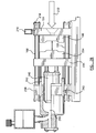
- injection molding machine 100 is shown in greater detail.
- machine injection unit 232 communicates with stationary machine platen 104 to deliver the melt stream thereto.
- mold cold-half 234 is attached to moving machine platen 236.
- moving machine platen 236 is movable along tie-bars 108 by stroke cylinders 242, allowing the mold hot-half 106 to mate with cold mold half 234 forming a complete injection mold.
- a clamp cylinder 244 includes a clamp column 240 that is attached to fixed clamp platen 238.
- the clamp column 240 pushes moving machine platen 236 and mold cold-half 234 toward the stationary mold hot-half 106 and maintains the cold-half 234 and hot-half 106 in abutment once mated in order to prevent separation during the injection process.
- sensors 110A, 110B, 110C that may be monitored as described are shown. These sensors include, but are not limited to, temperature sensors 110A, pressure sensors 110B, and valve pin position sensors 110C.
- the controllable devices 109 include heater 109A and valve pin 109C.
- Cable 222 which was shown in Figure 1 , is shown in greater detail in an embodiment for two zones.
- a typical injection molding machine includes many more zones, however two are depicted here for simplicity.
- Each zone includes a mold cable 250A, 250B, which is coupled to mold plate connector 220, a custom mold connector 252A, 252B and a hot runner connector 254A, 254B.
- Adapters 256 and machine cables 258 for the hot runner connectors 254A, 254B link the runner connectors 254A, 254B to the machine plate connector 218, which in turn is connected to control module 216.
- the adapters 256 allow the control module to be linked to injection molds of various manufacturers.
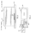
- a display interface module (DIM) 226, which is shown in Figure 1 is provided.
- the DIM 226 has three main functions. Referring to the block diagram of Figure 4 , one function of DIM 226 is to receive processed sensor output data signals 480 from control module 216, store data 480 in a memory 488 located within a DIM control unit 484, and display data 480 to a user upon a screen 486.
- a second function of DIM 226 is to accept user-entered set-point data such as temperature set-point data or pressure set-point data, for example, store user-entered set-point data in a memory 488 located within the DIM control unit 484, and provide user-entered set-point data 482 to control module 216.
- Communication including signals 480, 482 between DIM 226 and control module 216, occur through a communications interface, such as a serial communications interface. These communications may be carried by wires within a process data cable, via wireless means, or by other means of communications commonly used or known by those skilled in the art. For example, communications between DIM 226 and control module 216 may be accomplished via transceiver 217 in control module 216 and transceiver 227 in DIM 226, shown in FIG. 1 .
- the communication carrier for communications to and from DIM 226 and control module 216 is depicted generically as 224.
- a third main function of DIM 226 is to switch the power to control module 216.
- the memory 488 within DIM 226 can store both historical information as collected from sensors 110 as well as user-entered set-point data 482 that represent desired values of processing conditions within mold hot-half 106.
- DIM 226 may also include memory, such as memory 488, for storing digital or video data collected from cameras that could be mounted within the injection molding system for monitoring purposes.
- DIM 226 is easily portable and can be interchanged with other injection molding machines.
- DIM 226 can stand apart from an injection molding system, can be hard-mounted onto the injection molding system, or can be attached to any convenient location on the injection molding machine using a magnet or a swingable arm (not shown), for example.
- the portability of DIM 226, along with its memory feature allow user-entered set-point data to be ready for immediate use on other injection molding systems within a manufacturing setting.
- FIG. 5 depicts a method of operating a control system of an injection molding machine 100 and is generally indicated by reference numeral 500.
- a processing condition of an injection mold is reported by a sensor within the injection mold.
- a control module such as that described above, collects the sensor output.
- the control module processes the sensor output.
- communications can be exchanged between the control module and a DIM.
- the communications of step 510 are further depicted in Figure 6 .
- a control signal is generated by the control module in response to the sensor output or in response to user-entered set-point data.
- the control signal is sent to a controllable device that is able to vary the processing condition per the control signal.
- the method repeats at step 502.
- the control signal does not have to be used only by the controllable device 109 within mold hot-half 106.
- a control signal is also sent to a separate machine controller (not shown) to adjust parameters used by the machine as well.
- the machine controller is the main controller of the injection molding system machine.
- Step 510 starts at step 602, and moves immediately to step 604.
- the control module provides processed sensor output to the DIM.
- the processed sensor output is stored in a memory of the DIM.
- the processed sensor output is displayed to a user at the DIM.
- the DIM can accept user-entered set-point data that is associated with a controllable device.
- the user-entered set-point data is stored in memory of the DIM.
- the DIM provides the user-entered set-point data to the control module.
- the method moves on to step 512 of FIG. 5 .
- processing sensors are located on the mold cold half 234 to monitor various processing conditions, such as the temperature of a mold core coolant, a heater or the mold cavity pressure.
- the wiring between the sensors 110 located on the mold cold half 234 and the control module 216 include snap-in connectors or other electrical contacts that physically disengage during the opening of the mold.
Landscapes
- Engineering & Computer Science (AREA)
- Mechanical Engineering (AREA)
- Manufacturing & Machinery (AREA)
- Injection Moulding Of Plastics Or The Like (AREA)
- Moulds For Moulding Plastics Or The Like (AREA)
Claims (7)
- Machine de moulage par injection comprenant :un moule d'injection monté sur un plateau (104) de machine, ledit moule à injection ayant un demi-moule chaud (106) et un demi-moule froid (234) ;au moins un dispositif contrôlable (109) couplé au moule d'injection pour modifier une condition de traitement du moule d'injection (106) ;au moins un capteur (110) couplé au moule d'injection (106) qui reporte une valeur de la condition de traitement ; etun module de commande (216), qui est en communication avec ledit au moins un capteur (110) et ledit au moins un dispositif contrôlable (109), moyennant quoi ledit module de commande est adapté pour collecter un résultat provenant dudit au moins un capteur (110), traiter ledit résultat de capteur et fournir un signal de commande audit au moins un dispositif contrôlable (109), caractérisée en ce que :le module de commande (216) est monté sur le plateau (104) de machine et ledit module de commande (216) est couplé audit plateau de machine (104) via un connecteur (218) de plaque de machine.
- Machine de moulage par injection selon la revendication 1, comprenant en outre :un connecteur (220) de plaque de moule couplé audit demi-moule chaud, ledit connecteur (220) de plaque de moule fournissant une liaison entre ledit au moins un capteur (110) et ledit module de commande (216) .
- Machine de moulage par injection selon l'une quelconque des revendications précédentes, comprenant en outre :un connecteur (220) de plaque de moule couplé audit demi-moule chaud, ledit connecteur (220) de plaque de moule fournissant une liaison entre ledit au moins un capteur (110) et ledit module de commande (216) ;dans laquelle ledit connecteur (218) de plaque de machine est couplé à un câble de moule (250) qui communique avec un câble de machine (258) qui est couplé audit connecteur (220) de plaque de moule.
- Machine de moulage par injection selon la revendication 3, dans laquelle on prévoit un adapteur (256) entre ledit câble de moule (250) et ledit câble de machine (258), ledit adapteur (256) étant amovible et interchangeable pour loger une pluralité de différents moules d'injection.
- Machine de moulage par injection selon au moins l'une des revendications précédentes, dans laquelle ledit dispositif contrôlable (109) est un dispositif de chauffage (109A).
- Machine de moulage par injection selon au moins l'une des revendications précédentes, dans laquelle ledit dispositif contrôlable (109) est une broche de soupape.
- Machine de moulage par injection selon au moins l'une des revendications précédentes, dans laquelle ledit au moins un capteur (110) est un thermocouple (110A).
Applications Claiming Priority (2)
| Application Number | Priority Date | Filing Date | Title |
|---|---|---|---|
| US47990903P | 2003-06-20 | 2003-06-20 | |
| US479909P | 2003-06-20 |
Publications (3)
| Publication Number | Publication Date |
|---|---|
| EP1488904A2 EP1488904A2 (fr) | 2004-12-22 |
| EP1488904A3 EP1488904A3 (fr) | 2005-01-26 |
| EP1488904B1 true EP1488904B1 (fr) | 2008-04-09 |
Family
ID=33418484
Family Applications (1)
| Application Number | Title | Priority Date | Filing Date |
|---|---|---|---|
| EP04014495A Expired - Lifetime EP1488904B1 (fr) | 2003-06-20 | 2004-06-21 | Dispositif de commande de moule et canal chaud monté sur le plateau porte-moule |
Country Status (6)
| Country | Link |
|---|---|
| US (1) | US7258536B2 (fr) |
| EP (1) | EP1488904B1 (fr) |
| JP (1) | JP2005007884A (fr) |
| CN (1) | CN100434253C (fr) |
| CA (1) | CA2471439A1 (fr) |
| DE (1) | DE602004012924T2 (fr) |
Families Citing this family (29)
| Publication number | Priority date | Publication date | Assignee | Title |
|---|---|---|---|---|
| US6331640B1 (en) | 1998-10-13 | 2001-12-18 | Hoffmann-La Roche Inc. | Diaminopropionic acid derivatives |
| DE102005049804A1 (de) * | 2004-10-18 | 2006-05-11 | Mold-Masters Limited, Georgetown | Mehrzoniger Temperaturregler für ein Spritzgiesssystem |
| US7580771B2 (en) * | 2004-10-19 | 2009-08-25 | Husky Injection Molding Systems Ltd. | Intelligent molding environment and method of configuring a molding system |
| ITTO20050158A1 (it) * | 2005-03-11 | 2006-09-12 | Incos Spa | Sistema di controllo energetico per apparecchiature di stampaggio ad iniezione di materie plastiche |
| US20070057394A1 (en) * | 2005-09-14 | 2007-03-15 | Thomas Linehan | Apparatus and method for temperature control |
| US20080088047A1 (en) * | 2006-10-12 | 2008-04-17 | Mold-Masters Limited | Apparatus and method for a hot runner injection molding system |
| PL1935609T3 (pl) * | 2006-12-22 | 2010-08-31 | Mold Masters 2007 Ltd | System do formowania wtryskowego zawierający magistralę |
| ITTV20060059U1 (it) * | 2006-12-28 | 2008-06-29 | Inglass Spa | Apparecchiatura di controllo per il monitoraggio di macchine per lo stampaggio ad iniezione di manufatti in materiale plastico. |
| US7412301B1 (en) * | 2007-02-08 | 2008-08-12 | Husky Injection Molding Systems Ltd. | Identifying quality molded article based on determination of plug blow |
| US7632438B2 (en) * | 2007-05-25 | 2009-12-15 | Husky Injection Molding Systems Ltd. | Intelligent manifold and injection molding machine |
| CN102149528B (zh) * | 2008-07-14 | 2013-08-28 | 圣万提注塑工业有限公司 | 注射成型流动控制装置及方法 |
| US7815840B2 (en) * | 2008-12-10 | 2010-10-19 | Ace Mold Company, Ltd. | Modular mold system and related method |
| US8280544B2 (en) | 2009-11-02 | 2012-10-02 | Mold Masters (2007) Limited | System for use in performance of injection molding operations |
| US8165714B2 (en) * | 2010-01-25 | 2012-04-24 | Husky Injection Molding Systems Ltd. | Controller for controlling combination of hot-runner system and mold assembly |
| WO2012082291A1 (fr) * | 2010-12-14 | 2012-06-21 | Husky Injection Molding Systems Ltd | Gestion thermique d'un système de moulage |
| EP2476320B2 (fr) * | 2011-01-12 | 2022-01-19 | Kraft Foods R & D, Inc. | Moule pour la formation d'au moins un produit alimentaire |
| US20120277900A1 (en) * | 2011-04-29 | 2012-11-01 | Mold-Masters (2007) Limited | Injection molding assembly having processing circuit |
| CN102328390A (zh) * | 2011-09-28 | 2012-01-25 | 凡嘉科技(无锡)有限公司 | 模具的线缆固定结构 |
| CN102672139A (zh) * | 2012-05-30 | 2012-09-19 | 创金美科技(深圳)有限公司 | 一种锌铝镁合金压铸模具及加工零件的方法 |
| DE102013012914A1 (de) | 2012-08-03 | 2014-02-20 | Gheorghe George Olaru | Hot runner injection molding apparatus with additional controller |
| CN106170380B (zh) | 2013-07-09 | 2018-03-16 | 赫斯基注塑系统有限公司 | 模具堆叠 |
| CN104309085B (zh) * | 2014-10-11 | 2016-08-24 | 浙江师范大学 | 一种在线监测微注塑中复合材料形态演变的装置及方法 |
| ITUB20156839A1 (it) | 2015-12-10 | 2017-06-10 | Inglass Spa | Apparecchiatura di stampaggio ad iniezione di materie plastiche |
| JP6576862B2 (ja) * | 2016-03-16 | 2019-09-18 | 東芝メモリ株式会社 | トランスファ成型装置 |
| US11402982B2 (en) | 2017-07-14 | 2022-08-02 | Synventive Molding Solutions, Inc. | Graphical interface for injection molding systems |
| JP6472860B1 (ja) * | 2017-10-17 | 2019-02-20 | 東芝機械株式会社 | 射出成形機 |
| CN115674614B (zh) * | 2022-12-30 | 2023-04-14 | 广东美的制冷设备有限公司 | 一种模具组件及注塑机 |
| CN117644614A (zh) * | 2023-12-29 | 2024-03-05 | 广东美的制冷设备有限公司 | 模具的传感器的自动布线方法及自动布线装置 |
| CN121798803B (zh) * | 2026-03-12 | 2026-05-08 | 江西昌兴航空装备股份有限公司 | 一种仿飞鱼航空无人机可控液体量的分块式成型模具 |
Family Cites Families (27)
| Publication number | Priority date | Publication date | Assignee | Title |
|---|---|---|---|---|
| US4023279A (en) * | 1972-09-14 | 1977-05-17 | Gammaflux, Inc. | Method and apparatus for drying moldable resins |
| JPS58222827A (ja) * | 1982-06-22 | 1983-12-24 | Sumitomo Heavy Ind Ltd | 射出成形用金型の自動交換装置 |
| CH668220A5 (de) * | 1984-02-28 | 1988-12-15 | Ju Oh Trading Co Ltd | Heisskanal-spritzgiessanlage. |
| US4648883A (en) * | 1984-07-25 | 1987-03-10 | Ciba-Geigy Corporation | Process for the preparation of storage stable aqueous formulations of anionic dyes: amon exchange resin treatment |
| JPS61134218A (ja) * | 1984-12-05 | 1986-06-21 | Shigeru Tsutsumi | 熱可塑性合成樹脂射出成形システムにおけるホツトランナ−の温度制御表示装置 |
| US4745541A (en) * | 1986-06-16 | 1988-05-17 | Cincinnati Milacron Inc. | Method and apparatus for process control |
| AT387292B (de) * | 1986-10-16 | 1988-12-27 | Stastny & Schroegendorfer | Verfahren zum messen und regeln der temperatur sowie vorrichtung zur herstellung von spritzgussteilen mit beheizten und/oder gekuehlten sowie temperaturgeregelten schmelzezufuehrungsleitungen |
| JPH0725116B2 (ja) * | 1986-10-30 | 1995-03-22 | フアナツク株式会社 | 遠隔起動・停止ができる射出成形機 |
| US4919608A (en) * | 1988-10-04 | 1990-04-24 | Roehr Tool Corporation | Molding apparatus with collapsible core |
| US5198240A (en) * | 1990-07-19 | 1993-03-30 | Nitrojection Corporation | Pressurization control unit for a gas-assisted injection molding machine |
| US5316707A (en) * | 1991-09-05 | 1994-05-31 | Tempcraft, Inc. | Injection molding apparatus control system and method of injection molding |
| JPH07119042B2 (ja) * | 1992-08-11 | 1995-12-20 | 日精樹脂工業株式会社 | 射出成形機の温度制御装置 |
| US5320513A (en) | 1992-12-10 | 1994-06-14 | Husky Injection Molding Systems Ltd. | Printed circuit board for an injection molding apparatus |
| JPH0832424B2 (ja) * | 1992-12-18 | 1996-03-29 | 藤夫 山田 | プラスチックのランナレス射出成形のためのホットノズルの温度制御装置 |
| US5523640A (en) * | 1994-04-22 | 1996-06-04 | Cincinnati Milacron Inc. | Liquid cooling for electrical components of a plastics processing machine |
| US5456870A (en) * | 1994-05-20 | 1995-10-10 | Van Dorn Demag Corporation | Barrel temperature state controller for injection molding machine |
| US5795511A (en) * | 1995-06-06 | 1998-08-18 | Fast Heat, Inc. | Method and apparatus for controlling injection-molding systems |
| US6421577B1 (en) | 1997-02-12 | 2002-07-16 | American Msi Corporation | Injection mold mounted process control and data acquisition apparatus |
| US6000831A (en) | 1997-02-12 | 1999-12-14 | American Msi Corporation | Injection mold data transmission system |
| US5922367A (en) * | 1997-03-26 | 1999-07-13 | The Whitaker Corporation | Injection mold having heated sprue bushing |
| US6275741B1 (en) * | 1998-10-05 | 2001-08-14 | Husky Injection Molding Systems Ltd. | Integrated control platform for injection molding system |
| JP3467206B2 (ja) | 1999-03-16 | 2003-11-17 | 世紀株式会社 | 制御ユニット一体型射出成形用金型 |
| US6529796B1 (en) * | 1999-07-21 | 2003-03-04 | Caco Pacific Corporation | Closed loop interactive controller |
| JP2001191381A (ja) | 2000-01-11 | 2001-07-17 | Niigata Eng Co Ltd | 射出成形機の設定表示装置 |
| CA2427832C (fr) * | 2000-11-06 | 2008-01-08 | Frederick J. Buja | Procede et appareil permettant de reguler un processus de moulage et d'ecoulement de fusion a l'aide de capteurs de temperature |
| JP4647802B2 (ja) | 2001-02-05 | 2011-03-09 | 高木産業株式会社 | 動作表示装置及びその方法 |
| US6913453B2 (en) * | 2003-04-24 | 2005-07-05 | Fast Heat Inc. | Apparatus for protecting thermocouple circuits in thermoplastic injection moulding equipment |
-
2004
- 2004-06-18 CA CA002471439A patent/CA2471439A1/fr not_active Abandoned
- 2004-06-19 CN CNB2004100550934A patent/CN100434253C/zh not_active Expired - Fee Related
- 2004-06-21 DE DE602004012924T patent/DE602004012924T2/de not_active Expired - Lifetime
- 2004-06-21 JP JP2004182601A patent/JP2005007884A/ja not_active Withdrawn
- 2004-06-21 EP EP04014495A patent/EP1488904B1/fr not_active Expired - Lifetime
- 2004-06-21 US US10/871,570 patent/US7258536B2/en not_active Expired - Lifetime
Also Published As
| Publication number | Publication date |
|---|---|
| EP1488904A2 (fr) | 2004-12-22 |
| US20040258787A1 (en) | 2004-12-23 |
| CN1590066A (zh) | 2005-03-09 |
| JP2005007884A (ja) | 2005-01-13 |
| CN100434253C (zh) | 2008-11-19 |
| US7258536B2 (en) | 2007-08-21 |
| EP1488904A3 (fr) | 2005-01-26 |
| CA2471439A1 (fr) | 2004-12-20 |
| DE602004012924T2 (de) | 2009-06-10 |
| DE602004012924D1 (de) | 2008-05-21 |
Similar Documents
| Publication | Publication Date | Title |
|---|---|---|
| US7258536B2 (en) | Mold and hot runner controller located on the machine platen | |
| EP1919686B1 (fr) | Appareil de moulage par injection comprenant un moule de type séparation et son procédé de commande | |
| JP3921344B2 (ja) | 金型、金型半部又は金型支持体、金型、金型半部又は金型支持体の保持装置及び保持装置への金型、金型半部又は金型支持体の挿入方法 | |
| US12311588B2 (en) | Injection molding machine | |
| CA2644229C (fr) | Systeme integre de production de composites | |
| CN108068285B (zh) | 匣盒模具式射出成型机 | |
| EP1019231B1 (fr) | Appareil de moulage rotatif utilisant un retour de thermometrie a infrarouge | |
| KR102203378B1 (ko) | 모니터링 장치 및 이를 포함하는 사출성형장치 모니터링 시스템 | |
| JP7032206B2 (ja) | 射出成形用データ管理装置、および射出成形機 | |
| JP6660443B2 (ja) | 射出成形装置および射出成形方法 | |
| CN102574318B (zh) | 用于控制或调节注入过程的方法 | |
| EP4302961A1 (fr) | Dispositif d'extrusion et matrice de moulage par extrusion utilisée par ce dernier, dispositif et programme de surveillance, procédé de fabrication de brin et procédé de réglage de diamètre de brin | |
| WO2023085283A1 (fr) | Dispositif de traitement d'informations, système de traitement d'informations, et programme | |
| US7245986B2 (en) | Control device for use in injection molding machine | |
| JP2940850B2 (ja) | 自動成形装置 | |
| EP3546180B1 (fr) | Système de gestion de machine de moulage par injection | |
| JPH10113966A (ja) | 射出成形機ユニット | |
| EP3888876A1 (fr) | Machine de moulage par injection et machine industrielle | |
| JP4585371B2 (ja) | 射出成形機の制御装置 | |
| US8287273B2 (en) | Method of and apparatus for changing colors of injection molding hot runner die | |
| CN115703262B (zh) | 注射成型机的控制装置、注射成型机及程序 | |
| CN112566768A (zh) | 热浇道装置 | |
| JP3707648B2 (ja) | 複数台の型締装置を備えた旋回式射出成形機の制御方法 | |
| JP2004155125A (ja) | 成形機の成形情報表示方法および成形情報管理システム | |
| CN220946553U (zh) | 注塑机 |
Legal Events
| Date | Code | Title | Description |
|---|---|---|---|
| PUAI | Public reference made under article 153(3) epc to a published international application that has entered the european phase |
Free format text: ORIGINAL CODE: 0009012 |
|
| PUAL | Search report despatched |
Free format text: ORIGINAL CODE: 0009013 |
|
| AK | Designated contracting states |
Kind code of ref document: A2 Designated state(s): AT BE BG CH CY CZ DE DK EE ES FI FR GB GR HU IE IT LI LU MC NL PL PT RO SE SI SK TR |
|
| AX | Request for extension of the european patent |
Extension state: AL HR LT LV MK |
|
| AK | Designated contracting states |
Kind code of ref document: A3 Designated state(s): AT BE BG CH CY CZ DE DK EE ES FI FR GB GR HU IE IT LI LU MC NL PL PT RO SE SI SK TR |
|
| AX | Request for extension of the european patent |
Extension state: AL HR LT LV MK |
|
| 17P | Request for examination filed |
Effective date: 20050713 |
|
| AKX | Designation fees paid |
Designated state(s): DE ES FR IT |
|
| GRAP | Despatch of communication of intention to grant a patent |
Free format text: ORIGINAL CODE: EPIDOSNIGR1 |
|
| GRAS | Grant fee paid |
Free format text: ORIGINAL CODE: EPIDOSNIGR3 |
|
| RAP1 | Party data changed (applicant data changed or rights of an application transferred) |
Owner name: MOLD-MASTERS (2007) LIMITED |
|
| GRAA | (expected) grant |
Free format text: ORIGINAL CODE: 0009210 |
|
| AK | Designated contracting states |
Kind code of ref document: B1 Designated state(s): DE ES FR IT |
|
| REF | Corresponds to: |
Ref document number: 602004012924 Country of ref document: DE Date of ref document: 20080521 Kind code of ref document: P |
|
| PG25 | Lapsed in a contracting state [announced via postgrant information from national office to epo] |
Ref country code: ES Free format text: LAPSE BECAUSE OF FAILURE TO SUBMIT A TRANSLATION OF THE DESCRIPTION OR TO PAY THE FEE WITHIN THE PRESCRIBED TIME-LIMIT Effective date: 20080720 |
|
| PGFP | Annual fee paid to national office [announced via postgrant information from national office to epo] |
Ref country code: FR Payment date: 20080630 Year of fee payment: 5 |
|
| EN | Fr: translation not filed | ||
| PLBE | No opposition filed within time limit |
Free format text: ORIGINAL CODE: 0009261 |
|
| STAA | Information on the status of an ep patent application or granted ep patent |
Free format text: STATUS: NO OPPOSITION FILED WITHIN TIME LIMIT |
|
| 26N | No opposition filed |
Effective date: 20090112 |
|
| PG25 | Lapsed in a contracting state [announced via postgrant information from national office to epo] |
Ref country code: FR Free format text: LAPSE BECAUSE OF FAILURE TO SUBMIT A TRANSLATION OF THE DESCRIPTION OR TO PAY THE FEE WITHIN THE PRESCRIBED TIME-LIMIT Effective date: 20090130 |
|
| PG25 | Lapsed in a contracting state [announced via postgrant information from national office to epo] |
Ref country code: IT Free format text: LAPSE BECAUSE OF FAILURE TO SUBMIT A TRANSLATION OF THE DESCRIPTION OR TO PAY THE FEE WITHIN THE PRESCRIBED TIME-LIMIT Effective date: 20080409 |
|
| PGFP | Annual fee paid to national office [announced via postgrant information from national office to epo] |
Ref country code: DE Payment date: 20210519 Year of fee payment: 18 |
|
| REG | Reference to a national code |
Ref country code: DE Ref legal event code: R119 Ref document number: 602004012924 Country of ref document: DE |
|
| PG25 | Lapsed in a contracting state [announced via postgrant information from national office to epo] |
Ref country code: DE Free format text: LAPSE BECAUSE OF NON-PAYMENT OF DUE FEES Effective date: 20230103 |