EP1489202A1 - Galvanisiertrommel, Galvanisiergerät mit Trommel und Abflusseinrichtung - Google Patents
Galvanisiertrommel, Galvanisiergerät mit Trommel und Abflusseinrichtung Download PDFInfo
- Publication number
- EP1489202A1 EP1489202A1 EP04012353A EP04012353A EP1489202A1 EP 1489202 A1 EP1489202 A1 EP 1489202A1 EP 04012353 A EP04012353 A EP 04012353A EP 04012353 A EP04012353 A EP 04012353A EP 1489202 A1 EP1489202 A1 EP 1489202A1
- Authority
- EP
- European Patent Office
- Prior art keywords
- barrel
- plating
- drain
- tool
- plating barrel
- Prior art date
- Legal status (The legal status is an assumption and is not a legal conclusion. Google has not performed a legal analysis and makes no representation as to the accuracy of the status listed.)
- Granted
Links
- 238000007747 plating Methods 0.000 title claims abstract description 147
- 239000007788 liquid Substances 0.000 claims abstract description 32
- 239000000463 material Substances 0.000 claims abstract description 29
- 239000004033 plastic Substances 0.000 claims abstract description 19
- 229920003023 plastic Polymers 0.000 claims abstract description 19
- 230000007246 mechanism Effects 0.000 claims description 10
- 238000005245 sintering Methods 0.000 claims description 2
- 238000007669 thermal treatment Methods 0.000 claims description 2
- 230000008901 benefit Effects 0.000 abstract description 10
- 238000000034 method Methods 0.000 description 11
- 230000008569 process Effects 0.000 description 11
- 238000009713 electroplating Methods 0.000 description 6
- 238000004519 manufacturing process Methods 0.000 description 5
- PXHVJJICTQNCMI-UHFFFAOYSA-N Nickel Chemical compound [Ni] PXHVJJICTQNCMI-UHFFFAOYSA-N 0.000 description 4
- 238000005516 engineering process Methods 0.000 description 4
- RYGMFSIKBFXOCR-UHFFFAOYSA-N Copper Chemical compound [Cu] RYGMFSIKBFXOCR-UHFFFAOYSA-N 0.000 description 3
- 238000010276 construction Methods 0.000 description 3
- 229910052802 copper Inorganic materials 0.000 description 3
- 239000010949 copper Substances 0.000 description 3
- 239000011796 hollow space material Substances 0.000 description 3
- 239000002184 metal Substances 0.000 description 3
- 229910052751 metal Inorganic materials 0.000 description 3
- 229920002972 Acrylic fiber Polymers 0.000 description 2
- 230000005611 electricity Effects 0.000 description 2
- 239000004744 fabric Substances 0.000 description 2
- 238000009434 installation Methods 0.000 description 2
- 150000002739 metals Chemical class 0.000 description 2
- 229910052759 nickel Inorganic materials 0.000 description 2
- -1 polyethylene Polymers 0.000 description 2
- 125000006850 spacer group Chemical group 0.000 description 2
- 239000004698 Polyethylene Substances 0.000 description 1
- 239000004743 Polypropylene Substances 0.000 description 1
- 229920006362 Teflon® Polymers 0.000 description 1
- 239000003990 capacitor Substances 0.000 description 1
- 239000000919 ceramic Substances 0.000 description 1
- 238000005553 drilling Methods 0.000 description 1
- 238000005868 electrolysis reaction Methods 0.000 description 1
- 239000007789 gas Substances 0.000 description 1
- 239000011521 glass Substances 0.000 description 1
- 150000004677 hydrates Chemical class 0.000 description 1
- 239000011810 insulating material Substances 0.000 description 1
- 239000012212 insulator Substances 0.000 description 1
- 238000003754 machining Methods 0.000 description 1
- 238000010297 mechanical methods and process Methods 0.000 description 1
- 230000005226 mechanical processes and functions Effects 0.000 description 1
- 239000011859 microparticle Substances 0.000 description 1
- 230000004048 modification Effects 0.000 description 1
- 238000012986 modification Methods 0.000 description 1
- 238000000465 moulding Methods 0.000 description 1
- 230000035699 permeability Effects 0.000 description 1
- 229920000728 polyester Polymers 0.000 description 1
- 229920000573 polyethylene Polymers 0.000 description 1
- 229920005672 polyolefin resin Polymers 0.000 description 1
- 229920001155 polypropylene Polymers 0.000 description 1
- 238000010926 purge Methods 0.000 description 1
- 239000008237 rinsing water Substances 0.000 description 1
- 238000007493 shaping process Methods 0.000 description 1
- 229910001220 stainless steel Inorganic materials 0.000 description 1
- 239000010935 stainless steel Substances 0.000 description 1
Images




Classifications
-
- C—CHEMISTRY; METALLURGY
- C25—ELECTROLYTIC OR ELECTROPHORETIC PROCESSES; APPARATUS THEREFOR
- C25D—PROCESSES FOR THE ELECTROLYTIC OR ELECTROPHORETIC PRODUCTION OF COATINGS; ELECTROFORMING; APPARATUS THEREFOR
- C25D17/00—Constructional parts, or assemblies thereof, of cells for electrolytic coating
- C25D17/16—Apparatus for electrolytic coating of small objects in bulk
- C25D17/18—Apparatus for electrolytic coating of small objects in bulk having closed containers
- C25D17/20—Horizontal barrels
-
- C—CHEMISTRY; METALLURGY
- C25—ELECTROLYTIC OR ELECTROPHORETIC PROCESSES; APPARATUS THEREFOR
- C25D—PROCESSES FOR THE ELECTROLYTIC OR ELECTROPHORETIC PRODUCTION OF COATINGS; ELECTROFORMING; APPARATUS THEREFOR
- C25D17/00—Constructional parts, or assemblies thereof, of cells for electrolytic coating
- C25D17/16—Apparatus for electrolytic coating of small objects in bulk
-
- C—CHEMISTRY; METALLURGY
- C25—ELECTROLYTIC OR ELECTROPHORETIC PROCESSES; APPARATUS THEREFOR
- C25D—PROCESSES FOR THE ELECTROLYTIC OR ELECTROPHORETIC PRODUCTION OF COATINGS; ELECTROFORMING; APPARATUS THEREFOR
- C25D17/00—Constructional parts, or assemblies thereof, of cells for electrolytic coating
- C25D17/16—Apparatus for electrolytic coating of small objects in bulk
- C25D17/22—Apparatus for electrolytic coating of small objects in bulk having open containers
- C25D17/24—Oblique barrels
Definitions
- the present invention relates to plating barrels, barrel plating apparatuses and drain tools to drain out plating liquid staying in the plating barrels.
- the barrel plating technology has been used.
- a bunch of small pieces of materials is put in a plating barrel (that is a barrel shape container or a cylindrical shape container) and the barrel is immersed in the plating liquid in order to plate the small pieces of materials (for example, see the reference 1) .
- a plating barrel that is a barrel shape container or a cylindrical shape container
- many holes or slits are made in the surrounding surface of the plating barrel.
- the size and the shape of the holes should be designed in such a way that no pieces of the material to be plated fall out from the plating barrel.
- the present invention has an advantage to provide a plating barrel which has much finer holes, slits or meshes as an order of 1 micro meter and has another advantage such that the plating barrel can be easily fabricated with low cost.
- the present invention has further advantage to provide a drain tool to drain out the plating liquid staying in such a plating barrel.
- the function of the plating barrel regarding to the present invention is to accommodate the piece parts to be plated and is to be immersed in the plating liquid.
- the plating barrel is formed in a mold of porous plastic that has a micro skeleton texture.
- the porous plastic is made by sintering the crashed plastic chips under thermal treatment.
- the plating barrel as made of the porous plastic has permeable holes that allow the plating liquid to come in or go out from the inside of the plating barrel, wherein the permeable holes are an order of micro meters. Therefore it is possible to plate the piece parts that have the size of an order of micro meters as well. No mechanical fabrication process to open holes, slits or meshes is required and therefore the fabrication of the plating barrel is easy and requires only low cost.
- the mother materials for the porous plastic are polyethylene, polypropylene, olefin resin products, polyester hydrates are used.
- the present invention has further advantage to provide the plating capability of small pieces such that a rotation mechanism is attached to the plating barrel and a cathode and an anode are installed in the plating barrel for the purpose of electroplating. Therefore, the present invention serves electroplating operation when DC electricity is applied with rotating the plating barrel.
- the drain tool regarding the present invention is to drain out the plating liquid in the plating barrel.
- the present invention has an advantage to drain the plating liquid out by means of suction which has featuring constructions such as a plating barrel holder and an outlet for exhausting the plating liquid.
- the present invention of the drain tool has an advantage to exhaust the plating liquid in the plating barrel in a quick manner so that the time for the plating process is easily managed and controlled.
- FIG. 1 and FIG. 2 show the plating barrel 10 and the barrel plating apparatus 1 regarding the present invention.
- FIG. 1 shows a cut-away view of a major portion of the plating barrel 10 and
- FIG. 2 shows a zoom up cross sectional view of the plating barrel 10.
- the barrel plating apparatus 1 comprises a plating barrel 10 accommodating piece materials T to be plated, a barrel holding tool 20, a pipe 30 that holds the barrel holding tool 20 and rotates therewith, a rotational drive mechanism 40 that rotates the barrel holding tool 20, an assembly board 50 to which the pipe 30 and the rotational drive mechanism 40 are assembled, an anode 60 and a cathode globe 70 which are installed in plating barrel 10 and a plating tank 80 which keeps the plating liquid L therein.
- the plating barrel 10 has a cylindrical shape with a closed bottom and an open top which has a brim portion 10b which is held by the barrel holder 91 at the stopper 91b of the drain tool 90 (see FIG. 3 and FIG. 4).
- the plating barrel 10 can be mounted to and dismounted from the barrel holding tool 20.
- the plating barrel 10 is mounted to the barrel holder tool 20 when the plating barrel 10 is used for the plating process.
- the piece materials T to be plated (that is, piece parts to be plated) are put into and taken out from the plating barrel 10 before and after the plating process are done, respectively.
- the piece parts are, for example, IC chips, surface mount electronic devices such as resistors, capacitors and inductors, small dimensional mechanical parts made of ceramics, glasses or plastics, micro particle metals, etc.
- the plating barrel is made of the porous plastic.
- the permeability of the porous plastic to the plating liquid L is caused by the skeleton texture of the crashed plastic chips which are thermally sintered. No fabric threads or furry surfaces are formed and therefore the piece materials T to be plated are not caught by, clutched to or stuck onto the surface of the porous plastic.
- the size of permeable holes or slits made in the porous plastic is smaller than the physical size of the piece materials T to be plated. Therefore no piece materials T are dropped off through the permeable holes or slits from the paling barrel while the plating process goes on. Neither piece materials T are captured by such permeable holes or slits.
- the porous plastic forms the barrel shape in a molding process, therefore no machining process such as drilling holes or barrel shaping is necessary.
- This provides a simple manufacturing process of the plating barrels.
- the piece materials T are contacting to the cathode plates.
- danglers work for the cathode electrical contact to the piece materials T. Since no piece materials T are caught by the porous plastic or captured by the permeable holes or slits, the electric supply by the dangler to the piece materials T are not shut off.
- the barrel holding tool 20 is made by a hollow cylinder which has two open ends and plural side windows 20a to let the plating liquid L come out from or go into the plating barrel 10.
- the plural side windows 20a work to purge the gases generated from the plating liquid L and staying in the plating barrel 10 in the plating process.
- the barrel holding tool 20 is fixed to a ring 31 seized by the pipe 30 at the upper end 20b and can rotate with the rotation of the pipe 30.
- the upper end 20b is fixed to the gear 43, that is, a part of the rotational drive mechanism 40 by fixing means such as screws.
- the pipe 30 is held by the assembly board 50 and penetrates therethrough.
- the pipe 30 is made of copper, stainless steel or other electrical conductive metals and coated by insulating material such as Teflon® .
- An electrical connection 32 which is connected to and anodic DC voltage is attached to the upper portion 30a of the pipe 30.
- the lower portion 30b of the pipe 30 is projected to the inside of the plating barrel 10.
- the rotational drive mechanism 40 is composed of a motor 41, a gear 42 attached to rotational axis 41a of the motor 41, another gear 43 meshing to the gear 42.
- the motor 41 is fixed to the assembly board 50 by screws.
- the pipe 30 is inserted into a center hole of the gear 43 which can freely rotate around the pipe 30. According to the mechanism of this rotational drive mechanism 40, the rotational axis 41a and gears 42 and 43 are rotated by the motor 41. Then the barrel holding tool 20 which is fixed to the gear 43 rotates.
- the pipe 30 is inserted to the ring spacer 44 that is fixed to the pipe 30 by screws.
- the assembly board 50 is made, for example, of acrylic plastic and formed in a rectangular of which one side, called a lower side 50a, is fixed to the upper portion 80a of the plating tank 80 by a mount 51 with a screw.
- the mount 51 composes of a clamp 51a which meets the upper portion 80a of the plating tank 80 and a wing bolt 51b by which the mount 51 is fixed to the tank.
- the assembly board 50 is fixed to the plating tank in a 45 degree tilting angle by screws so that the rotational drive mechanism 40 locates above the plating tank 80.
- the anode 60 is made of copper, nickel, etc. and formed in a cylindrical shape.
- the anode 60 is inserted and fixed to the end of the pipe 30.
- the inner hole 60a of the anode 60 is continued to the hollow space 30c of the pipe 30.
- the cathode cable 71 is inserted in inner hole 60a, the hollow space 30c of the anode 60 and the pipe 30 as shows in FIG. 1.
- the cathode cable 71 is connected to the cathode voltage terminal of the DC power (not shown in figures).
- a cathode globe 70 is put into the bottom of the plating barrel 10 and can electrically contact with the piece materials T staying in the bottom of the plating barrel.
- the electricity is supplied to the cathode globe 70 through a cathode cable 71 on which an insulator is coated.
- the other end of the cathode cable is connected to the cathode port of an electric power supplier (not shown in figures) .
- the cathode cable 71 is placed through the inner hole 60a of the anode 60 and hollow space 30c of the pipe 30.
- the plating tank 80 is made, for example, of transparent acrylic plastic and the copper iodized solution, nickel iodized solution, etc. is used for the plating liquid L.
- the plating process is carried out as follows.
- the piece materials T to be plated are put in the plating barrel 10 which is immersed into the plating liquid L staying in the plating tank 80.
- the plating barrel 10 is rotated with the barrel holding tool 20 by rotating the motor 41.
- the DC power is connected to the anode 60 attached to the pipe 30 and the cathode globe 7 though cathode cable 71 extending to the inside of the plating barrel 10.
- electroplating is done for the piece materials T which is stored in the plating barrel 10.
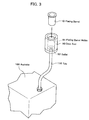
- FIG. 3 shows the drain tool 90 and the relevant tools.
- FIG. 4 shows the cut away view of the drain tool 90.
- FIG. 5 shows the installation of the drain tool 90 to an exhaust tank 120.
- the drain tool 90 is used before taking out the piece materials T in the plating barrel 10 after plating process has been over, especially is used to exhaust out the plating liquid L staying in the plating barrel 10.
- the drain tool 90 has a cylindrical form with an open cut in the upper end and has a bottom in the lower end.
- a plating barrel holder 91 has a space between the bottom 10a of the plating barrel 10 and the bottom 91a of the plating barrel holder 91.
- a stopper 91b is formed to meet the brim portion 10b of the plating barrel 10 .
- an outlet 92 to which a tube 110 linked to an aspirator 100 is inserted is formed.
- the aspirator 100 and the tube 110 work as an aspirating means.
- the plating barrel 10 When it is necessary to drain out the plating liquid L in the plating barrel 10, the plating barrel 10 is inserted in the plating barrel holder 91 in the drain tool 90.
- the plating liquid L in the plating barrel 10 can be quickly and easily aspirated by operating the aspirator 100.
- the advantage of quick exhaust of plating liquid L is that the time when piece materials T are immersed in the plating liquid L is short therefore no stains are made on the plating surfaces of the piece materials T since the electrolytic plating solution is quickly removed off from the surface of the piece materials T. The removal of such solution can be more effectively done when the rinsing water is sprinkled over the piece materials T during when the aspirator 100 works.
- the drain tool 90 can be used in attaching to the exhaust tank 120.
- the drain tool 90 is fixed to the bottom 120a of the exhaust tank 120.
- the first drain channel 121 is made extending from the outlet 92 of the drain tool 90 on the bottom 120a to the base outlet to which the tube 110 is connected.
- the second drain channel 122 to drain out the plating liquid L spilled out or overflowing is made in the bottom 120a of the exhaust tank 120.
- a tap 123 is attached to the base outlet of the second drain channel 122.
- the plating barrel 10 in the previous embodiment has a cylindrical shape but can be other shapes such as polygon columns.
- the plating barrel holder 91 is formed to meet such shapes.
- the anode 60 is present inside of the plating barrel 10.
- the plating barrel 10 is immersed in the electrolysis plating liquid L as called plating liquid L.
- the present embodiment shows the case where electroplating is carried out, however the plating barrel 10 of the barrel plating apparatus regarding the present invention can be used for electroless wet plating as well.
- the present invention can provide a barrel plating apparatus 1 where a plating barrel 10 which has permeable holes and slits in a size of micrometers on the wall gaps is used.
- Another advantage of the present invention is the ease of fabrication of such plating barrel 10 due to the use of porous plastic materials.
- Further advantage of the present invention is to provide a drain tool 90 to drain the plating liquid L staying in the plating barrel 10 thereout.
Landscapes
- Chemical & Material Sciences (AREA)
- Engineering & Computer Science (AREA)
- Chemical Kinetics & Catalysis (AREA)
- Electrochemistry (AREA)
- Materials Engineering (AREA)
- Metallurgy (AREA)
- Organic Chemistry (AREA)
- Electroplating Methods And Accessories (AREA)
- Chemically Coating (AREA)
- Coating With Molten Metal (AREA)
- Electrolytic Production Of Metals (AREA)
Applications Claiming Priority (2)
| Application Number | Priority Date | Filing Date | Title |
|---|---|---|---|
| JP2003172982 | 2003-06-18 | ||
| JP2003172982A JP3689415B2 (ja) | 2003-06-18 | 2003-06-18 | バレル、バレルめっき装置及び液排出具 |
Publications (2)
| Publication Number | Publication Date |
|---|---|
| EP1489202A1 true EP1489202A1 (de) | 2004-12-22 |
| EP1489202B1 EP1489202B1 (de) | 2009-03-18 |
Family
ID=33410946
Family Applications (1)
| Application Number | Title | Priority Date | Filing Date |
|---|---|---|---|
| EP04012353A Expired - Lifetime EP1489202B1 (de) | 2003-06-18 | 2004-05-25 | Galvanisiertrommel, Galvanisiergerät mit Trommel und Abflusseinrichtung |
Country Status (8)
| Country | Link |
|---|---|
| US (2) | US20040256220A1 (de) |
| EP (1) | EP1489202B1 (de) |
| JP (1) | JP3689415B2 (de) |
| KR (1) | KR100978393B1 (de) |
| CN (2) | CN1847467B (de) |
| AT (1) | ATE426053T1 (de) |
| DE (1) | DE602004020021D1 (de) |
| TW (1) | TWI249591B (de) |
Cited By (1)
| Publication number | Priority date | Publication date | Assignee | Title |
|---|---|---|---|---|
| CN104047044A (zh) * | 2014-07-04 | 2014-09-17 | 旺诠科技(昆山)有限公司 | 向电镀滚筒中加装电镀液的循环机构 |
Families Citing this family (13)
| Publication number | Priority date | Publication date | Assignee | Title |
|---|---|---|---|---|
| KR100889293B1 (ko) * | 2008-07-14 | 2009-03-17 | 주식회사 이즈컨텍 | 도금용 바렐 |
| CN102797026A (zh) * | 2012-08-16 | 2012-11-28 | 成都崇安科技有限公司 | 倾斜式锥度形六方滚筒点镀装置 |
| CN104894626B (zh) * | 2015-06-20 | 2017-09-08 | 浙江大学 | 一种用于对球状微米颗粒进行负载的可旋转电镀实验装置 |
| KR101709692B1 (ko) | 2015-11-30 | 2017-02-23 | 주식회사 포스코 | 도금욕조의 도금액 자동배출장치 및 자동배출방법 |
| JP6276454B1 (ja) * | 2017-05-26 | 2018-02-07 | 高島産業株式会社 | バレルめっき装置およびめっき方法 |
| US10844507B2 (en) * | 2017-06-21 | 2020-11-24 | Lawrence Livermore National Security, Llc | Cathode system for electrodeposition of metals on microspheres |
| CN108642545B (zh) * | 2018-05-29 | 2020-11-03 | 泗县泽农秸秆回收利用有限公司 | 一种镁合金微弧氧化设备 |
| CN112064100B (zh) * | 2020-09-15 | 2021-06-11 | 重庆工程职业技术学院 | 一种低耗镀液量微型滚镀机 |
| KR102510275B1 (ko) * | 2021-06-02 | 2023-03-15 | 주식회사 에이로플 | 바렐을 이용한 도금 기구 |
| KR102456153B1 (ko) * | 2022-07-22 | 2022-10-19 | 주식회사 에이치테크놀로지 | 도금 장치 |
| CN115710740B (zh) * | 2022-10-26 | 2025-08-01 | 中国航发北京航科发动机控制系统科技有限公司 | 一种利用氰化银溶液对转子多孔及端面均匀电镀银工装 |
| JP2025084223A (ja) * | 2023-11-22 | 2025-06-03 | 株式会社島谷技研 | メッキ被処理物の撹拌装置 |
| CN119800480B (zh) * | 2025-03-14 | 2025-09-12 | 江苏橙柳新能源科技有限公司 | 一种间歇式电池钢壳加工滚镀系统及加工方法 |
Citations (7)
| Publication number | Priority date | Publication date | Assignee | Title |
|---|---|---|---|---|
| US2500861A (en) * | 1945-06-30 | 1950-03-14 | Udylite Corp | Machine for treating articles in bulk |
| US3282819A (en) * | 1962-12-05 | 1966-11-01 | Leonard B Hovanic | Treating of workpieces |
| US4078297A (en) * | 1975-01-23 | 1978-03-14 | National Plastics & Plating Supply Co., Inc. | Electroplating barrel sidewall construction and method of making |
| US4257864A (en) * | 1979-08-02 | 1981-03-24 | Gacki Leonard W | Portable silver recovery unit |
| US5326403A (en) * | 1991-12-04 | 1994-07-05 | Towa Koki Kabushiki Kaisha | Equipment for discharging treated articles from a barrel in a surface treatment system |
| WO1996037638A1 (en) * | 1995-05-22 | 1996-11-28 | Griego Thomas P | Fine particle microencapsulation and electroforming |
| US6322685B1 (en) * | 1998-05-13 | 2001-11-27 | International Business Machines Corporation | Apparatus and method for plating coatings on to fine powder materials and use of the powder therefrom |
Family Cites Families (13)
| Publication number | Priority date | Publication date | Assignee | Title |
|---|---|---|---|---|
| US1916465A (en) * | 1929-04-08 | 1933-07-04 | Western Cartridge Co | Process and apparatus for electroplating projectiles |
| DE1796045C3 (de) * | 1968-08-20 | 1980-06-26 | Schering Ag, 1000 Berlin Und 4619 Bergkamen | Galvanisiertrommel zur Oberflächenbehandlung von Gegenständen |
| US3850737A (en) * | 1972-12-26 | 1974-11-26 | Trw Inc | Electroplating barrel with internal anode and cathode |
| US4390399A (en) * | 1980-11-24 | 1983-06-28 | Mcinnes Robert | Method and apparatus for plating articles |
| US4537669A (en) * | 1984-04-06 | 1985-08-27 | Mcinnes Robert | Apparatus for cleaning, plating and/or coating articles |
| US5057202A (en) * | 1990-07-09 | 1991-10-15 | Maitino Phillip M | Electrolytic recovery unit |
| EP0655268B1 (de) * | 1993-11-30 | 1998-04-08 | Joachim Dipl.-Ing. Geldmacher | Filter zum kontinuierlichen Filtrieren von Feststoffe aufweisenden Flüssigkeiten in einem geschlossenen, zylindrischen Behälter |
| US5879520A (en) * | 1994-08-26 | 1999-03-09 | Griego; Thomas P. | Rotary electrodeposition apparatus |
| US6228230B1 (en) * | 1999-04-19 | 2001-05-08 | Aem, Inc. | Electroplating apparatus |
| ATE333487T1 (de) * | 2000-02-07 | 2006-08-15 | Nagoya Oilchemical | Harzzusammensetzung, formmaterial und geformter gegenstand |
| TWI228548B (en) * | 2000-05-26 | 2005-03-01 | Ebara Corp | Apparatus for processing substrate and apparatus for processing treatment surface of substrate |
| JP2001334272A (ja) * | 2000-05-29 | 2001-12-04 | Sharp Corp | 汚水浄化装置及びそれを備えた洗濯機 |
| JP3389221B2 (ja) | 2001-02-13 | 2003-03-24 | ハセ技研株式会社 | バレルめっき装置 |
-
2003
- 2003-06-18 JP JP2003172982A patent/JP3689415B2/ja not_active Expired - Fee Related
-
2004
- 2004-05-14 TW TW093113614A patent/TWI249591B/zh not_active IP Right Cessation
- 2004-05-25 AT AT04012353T patent/ATE426053T1/de not_active IP Right Cessation
- 2004-05-25 DE DE602004020021T patent/DE602004020021D1/de not_active Expired - Lifetime
- 2004-05-25 EP EP04012353A patent/EP1489202B1/de not_active Expired - Lifetime
- 2004-05-28 US US10/855,615 patent/US20040256220A1/en not_active Abandoned
- 2004-06-02 CN CN2006100665782A patent/CN1847467B/zh not_active Expired - Fee Related
- 2004-06-02 KR KR1020040039945A patent/KR100978393B1/ko not_active Expired - Fee Related
- 2004-06-02 CN CNB2004100461625A patent/CN1303262C/zh not_active Expired - Fee Related
-
2006
- 2006-06-29 US US11/476,762 patent/US7828945B2/en not_active Expired - Fee Related
Patent Citations (7)
| Publication number | Priority date | Publication date | Assignee | Title |
|---|---|---|---|---|
| US2500861A (en) * | 1945-06-30 | 1950-03-14 | Udylite Corp | Machine for treating articles in bulk |
| US3282819A (en) * | 1962-12-05 | 1966-11-01 | Leonard B Hovanic | Treating of workpieces |
| US4078297A (en) * | 1975-01-23 | 1978-03-14 | National Plastics & Plating Supply Co., Inc. | Electroplating barrel sidewall construction and method of making |
| US4257864A (en) * | 1979-08-02 | 1981-03-24 | Gacki Leonard W | Portable silver recovery unit |
| US5326403A (en) * | 1991-12-04 | 1994-07-05 | Towa Koki Kabushiki Kaisha | Equipment for discharging treated articles from a barrel in a surface treatment system |
| WO1996037638A1 (en) * | 1995-05-22 | 1996-11-28 | Griego Thomas P | Fine particle microencapsulation and electroforming |
| US6322685B1 (en) * | 1998-05-13 | 2001-11-27 | International Business Machines Corporation | Apparatus and method for plating coatings on to fine powder materials and use of the powder therefrom |
Non-Patent Citations (1)
| Title |
|---|
| PATENT ABSTRACTS OF JAPAN vol. 1997, no. 12 25 December 1997 (1997-12-25) * |
Cited By (1)
| Publication number | Priority date | Publication date | Assignee | Title |
|---|---|---|---|---|
| CN104047044A (zh) * | 2014-07-04 | 2014-09-17 | 旺诠科技(昆山)有限公司 | 向电镀滚筒中加装电镀液的循环机构 |
Also Published As
| Publication number | Publication date |
|---|---|
| JP3689415B2 (ja) | 2005-08-31 |
| CN1847467B (zh) | 2010-08-18 |
| CN1303262C (zh) | 2007-03-07 |
| US7828945B2 (en) | 2010-11-09 |
| KR100978393B1 (ko) | 2010-08-26 |
| US20040256220A1 (en) | 2004-12-23 |
| DE602004020021D1 (de) | 2009-04-30 |
| US20060243586A1 (en) | 2006-11-02 |
| CN1572916A (zh) | 2005-02-02 |
| ATE426053T1 (de) | 2009-04-15 |
| HK1070400A1 (en) | 2005-06-17 |
| JP2005008927A (ja) | 2005-01-13 |
| CN1847467A (zh) | 2006-10-18 |
| KR20040110976A (ko) | 2004-12-31 |
| TWI249591B (en) | 2006-02-21 |
| EP1489202B1 (de) | 2009-03-18 |
| TW200502440A (en) | 2005-01-16 |
Similar Documents
| Publication | Publication Date | Title |
|---|---|---|
| US7828945B2 (en) | Plating barrel, barrel plating apparatus and drain equipment | |
| KR102244497B1 (ko) | 소형부품 전기도금 장치 | |
| JP2014237865A (ja) | 電解銅めっき装置 | |
| JP4991078B2 (ja) | 過マンガン酸塩エッチング溶液の電気化学再生用のカソード、該カソードの製造方法及び該カソードを有する装置 | |
| KR101027810B1 (ko) | 액체 탱크 | |
| CN212293829U (zh) | 一种电镀槽中电镀液的清理装置 | |
| US20110272283A1 (en) | Tube electroforming method, tube by electroforming, and thin wire material for production of tubes by electroforming | |
| KR20150144496A (ko) | 폐수에서 고순도로 구리를 회수하는 전해채취 설비 및 그 방법 | |
| CN101492831A (zh) | 电镀用阳极装置及包括该阳极装置的电镀装置 | |
| US7811440B2 (en) | Plating apparatus and plating method | |
| JP2002339100A (ja) | バレルめっき装置 | |
| WO2017037757A1 (ja) | 表面処理装置 | |
| HK1070400B (en) | Plating barrel and barrel plating apparatus | |
| CN110117811B (zh) | 一种电镀处理设备 | |
| JP4198161B2 (ja) | バレルめっき方法 | |
| CN104746115A (zh) | 一种微电解池局部电镀装置 | |
| EP1728897B1 (de) | Elektrogussrohrherstellungsverfahren und elektrogussrohr | |
| CN212881214U (zh) | 一种电镀药水生产用过滤装置 | |
| JP2017186677A (ja) | 電解銅めっき装置 | |
| CN113122905A (zh) | 电化学抛光液回收装置与方法 | |
| KR102295173B1 (ko) | 멀티-레이어 다이아몬드 전착 마이크로공구를 제조하는 전착장치 및 이를 이용한 멀티-레이어 다이아몬드 전착 마이크로공구를 제조하는 제조방법 | |
| KR100849158B1 (ko) | 전주관의 제조 방법 및 전주관, 전주관을 제조하기 위한세선재 | |
| CN209798153U (zh) | 一种能够使得电镀阴极上下接触的装置 | |
| KR20060111394A (ko) | 화학적 에칭보조 스파크 기계가공 헤드 | |
| KR101315335B1 (ko) | 산업용 금 회수장치 |
Legal Events
| Date | Code | Title | Description |
|---|---|---|---|
| PUAI | Public reference made under article 153(3) epc to a published international application that has entered the european phase |
Free format text: ORIGINAL CODE: 0009012 |
|
| AK | Designated contracting states |
Kind code of ref document: A1 Designated state(s): AT BE BG CH CY CZ DE DK EE ES FI FR GB GR HU IE IT LI LU MC NL PL PT RO SE SI SK TR |
|
| AX | Request for extension of the european patent |
Extension state: AL HR LT LV MK |
|
| 17P | Request for examination filed |
Effective date: 20050621 |
|
| AKX | Designation fees paid |
Designated state(s): AT BE BG CH CY CZ DE DK EE ES FI FR GB GR HU IE IT LI LU MC NL PL PT RO SE SI SK TR |
|
| GRAP | Despatch of communication of intention to grant a patent |
Free format text: ORIGINAL CODE: EPIDOSNIGR1 |
|
| GRAS | Grant fee paid |
Free format text: ORIGINAL CODE: EPIDOSNIGR3 |
|
| GRAA | (expected) grant |
Free format text: ORIGINAL CODE: 0009210 |
|
| AK | Designated contracting states |
Kind code of ref document: B1 Designated state(s): AT BE BG CH CY CZ DE DK EE ES FI FR GB GR HU IE IT LI LU MC NL PL PT RO SE SI SK TR |
|
| REG | Reference to a national code |
Ref country code: GB Ref legal event code: FG4D |
|
| REG | Reference to a national code |
Ref country code: CH Ref legal event code: NV Representative=s name: BOHEST AG Ref country code: CH Ref legal event code: EP |
|
| REG | Reference to a national code |
Ref country code: IE Ref legal event code: FG4D |
|
| REF | Corresponds to: |
Ref document number: 602004020021 Country of ref document: DE Date of ref document: 20090430 Kind code of ref document: P |
|
| PG25 | Lapsed in a contracting state [announced via postgrant information from national office to epo] |
Ref country code: NL Free format text: LAPSE BECAUSE OF FAILURE TO SUBMIT A TRANSLATION OF THE DESCRIPTION OR TO PAY THE FEE WITHIN THE PRESCRIBED TIME-LIMIT Effective date: 20090318 Ref country code: FI Free format text: LAPSE BECAUSE OF FAILURE TO SUBMIT A TRANSLATION OF THE DESCRIPTION OR TO PAY THE FEE WITHIN THE PRESCRIBED TIME-LIMIT Effective date: 20090318 Ref country code: SI Free format text: LAPSE BECAUSE OF FAILURE TO SUBMIT A TRANSLATION OF THE DESCRIPTION OR TO PAY THE FEE WITHIN THE PRESCRIBED TIME-LIMIT Effective date: 20090318 |
|
| PG25 | Lapsed in a contracting state [announced via postgrant information from national office to epo] |
Ref country code: SE Free format text: LAPSE BECAUSE OF FAILURE TO SUBMIT A TRANSLATION OF THE DESCRIPTION OR TO PAY THE FEE WITHIN THE PRESCRIBED TIME-LIMIT Effective date: 20090618 Ref country code: PL Free format text: LAPSE BECAUSE OF FAILURE TO SUBMIT A TRANSLATION OF THE DESCRIPTION OR TO PAY THE FEE WITHIN THE PRESCRIBED TIME-LIMIT Effective date: 20090318 Ref country code: AT Free format text: LAPSE BECAUSE OF FAILURE TO SUBMIT A TRANSLATION OF THE DESCRIPTION OR TO PAY THE FEE WITHIN THE PRESCRIBED TIME-LIMIT Effective date: 20090318 |
|
| NLV1 | Nl: lapsed or annulled due to failure to fulfill the requirements of art. 29p and 29m of the patents act | ||
| PG25 | Lapsed in a contracting state [announced via postgrant information from national office to epo] |
Ref country code: BE Free format text: LAPSE BECAUSE OF FAILURE TO SUBMIT A TRANSLATION OF THE DESCRIPTION OR TO PAY THE FEE WITHIN THE PRESCRIBED TIME-LIMIT Effective date: 20090318 |
|
| PG25 | Lapsed in a contracting state [announced via postgrant information from national office to epo] |
Ref country code: EE Free format text: LAPSE BECAUSE OF FAILURE TO SUBMIT A TRANSLATION OF THE DESCRIPTION OR TO PAY THE FEE WITHIN THE PRESCRIBED TIME-LIMIT Effective date: 20090318 Ref country code: CZ Free format text: LAPSE BECAUSE OF FAILURE TO SUBMIT A TRANSLATION OF THE DESCRIPTION OR TO PAY THE FEE WITHIN THE PRESCRIBED TIME-LIMIT Effective date: 20090318 Ref country code: ES Free format text: LAPSE BECAUSE OF FAILURE TO SUBMIT A TRANSLATION OF THE DESCRIPTION OR TO PAY THE FEE WITHIN THE PRESCRIBED TIME-LIMIT Effective date: 20090629 Ref country code: PT Free format text: LAPSE BECAUSE OF FAILURE TO SUBMIT A TRANSLATION OF THE DESCRIPTION OR TO PAY THE FEE WITHIN THE PRESCRIBED TIME-LIMIT Effective date: 20090826 |
|
| PG25 | Lapsed in a contracting state [announced via postgrant information from national office to epo] |
Ref country code: RO Free format text: LAPSE BECAUSE OF FAILURE TO SUBMIT A TRANSLATION OF THE DESCRIPTION OR TO PAY THE FEE WITHIN THE PRESCRIBED TIME-LIMIT Effective date: 20090318 Ref country code: SK Free format text: LAPSE BECAUSE OF FAILURE TO SUBMIT A TRANSLATION OF THE DESCRIPTION OR TO PAY THE FEE WITHIN THE PRESCRIBED TIME-LIMIT Effective date: 20090318 |
|
| PG25 | Lapsed in a contracting state [announced via postgrant information from national office to epo] |
Ref country code: MC Free format text: LAPSE BECAUSE OF NON-PAYMENT OF DUE FEES Effective date: 20090531 |
|
| PLBE | No opposition filed within time limit |
Free format text: ORIGINAL CODE: 0009261 |
|
| STAA | Information on the status of an ep patent application or granted ep patent |
Free format text: STATUS: NO OPPOSITION FILED WITHIN TIME LIMIT |
|
| PG25 | Lapsed in a contracting state [announced via postgrant information from national office to epo] |
Ref country code: DK Free format text: LAPSE BECAUSE OF FAILURE TO SUBMIT A TRANSLATION OF THE DESCRIPTION OR TO PAY THE FEE WITHIN THE PRESCRIBED TIME-LIMIT Effective date: 20090318 Ref country code: BG Free format text: LAPSE BECAUSE OF FAILURE TO SUBMIT A TRANSLATION OF THE DESCRIPTION OR TO PAY THE FEE WITHIN THE PRESCRIBED TIME-LIMIT Effective date: 20090618 |
|
| 26N | No opposition filed |
Effective date: 20091221 |
|
| GBPC | Gb: european patent ceased through non-payment of renewal fee |
Effective date: 20090618 |
|
| REG | Reference to a national code |
Ref country code: IE Ref legal event code: MM4A |
|
| PG25 | Lapsed in a contracting state [announced via postgrant information from national office to epo] |
Ref country code: IE Free format text: LAPSE BECAUSE OF NON-PAYMENT OF DUE FEES Effective date: 20090525 |
|
| PG25 | Lapsed in a contracting state [announced via postgrant information from national office to epo] |
Ref country code: GB Free format text: LAPSE BECAUSE OF NON-PAYMENT OF DUE FEES Effective date: 20090618 |
|
| PG25 | Lapsed in a contracting state [announced via postgrant information from national office to epo] |
Ref country code: GR Free format text: LAPSE BECAUSE OF FAILURE TO SUBMIT A TRANSLATION OF THE DESCRIPTION OR TO PAY THE FEE WITHIN THE PRESCRIBED TIME-LIMIT Effective date: 20090619 |
|
| PG25 | Lapsed in a contracting state [announced via postgrant information from national office to epo] |
Ref country code: IT Free format text: LAPSE BECAUSE OF FAILURE TO SUBMIT A TRANSLATION OF THE DESCRIPTION OR TO PAY THE FEE WITHIN THE PRESCRIBED TIME-LIMIT Effective date: 20090318 |
|
| PG25 | Lapsed in a contracting state [announced via postgrant information from national office to epo] |
Ref country code: LU Free format text: LAPSE BECAUSE OF NON-PAYMENT OF DUE FEES Effective date: 20090525 |
|
| PG25 | Lapsed in a contracting state [announced via postgrant information from national office to epo] |
Ref country code: HU Free format text: LAPSE BECAUSE OF FAILURE TO SUBMIT A TRANSLATION OF THE DESCRIPTION OR TO PAY THE FEE WITHIN THE PRESCRIBED TIME-LIMIT Effective date: 20090919 |
|
| PG25 | Lapsed in a contracting state [announced via postgrant information from national office to epo] |
Ref country code: TR Free format text: LAPSE BECAUSE OF FAILURE TO SUBMIT A TRANSLATION OF THE DESCRIPTION OR TO PAY THE FEE WITHIN THE PRESCRIBED TIME-LIMIT Effective date: 20090318 |
|
| PG25 | Lapsed in a contracting state [announced via postgrant information from national office to epo] |
Ref country code: CY Free format text: LAPSE BECAUSE OF FAILURE TO SUBMIT A TRANSLATION OF THE DESCRIPTION OR TO PAY THE FEE WITHIN THE PRESCRIBED TIME-LIMIT Effective date: 20090318 |
|
| REG | Reference to a national code |
Ref country code: CH Ref legal event code: PCAR Free format text: NEW ADDRESS: HOLBEINSTRASSE 36-38, 4051 BASEL (CH) |
|
| REG | Reference to a national code |
Ref country code: FR Ref legal event code: PLFP Year of fee payment: 13 |
|
| REG | Reference to a national code |
Ref country code: FR Ref legal event code: PLFP Year of fee payment: 14 |
|
| REG | Reference to a national code |
Ref country code: FR Ref legal event code: PLFP Year of fee payment: 15 |
|
| PGFP | Annual fee paid to national office [announced via postgrant information from national office to epo] |
Ref country code: CH Payment date: 20180525 Year of fee payment: 15 Ref country code: DE Payment date: 20180625 Year of fee payment: 15 |
|
| PGFP | Annual fee paid to national office [announced via postgrant information from national office to epo] |
Ref country code: FR Payment date: 20180525 Year of fee payment: 15 |
|
| REG | Reference to a national code |
Ref country code: DE Ref legal event code: R119 Ref document number: 602004020021 Country of ref document: DE |
|
| REG | Reference to a national code |
Ref country code: CH Ref legal event code: PL |
|
| PG25 | Lapsed in a contracting state [announced via postgrant information from national office to epo] |
Ref country code: CH Free format text: LAPSE BECAUSE OF NON-PAYMENT OF DUE FEES Effective date: 20190531 Ref country code: LI Free format text: LAPSE BECAUSE OF NON-PAYMENT OF DUE FEES Effective date: 20190531 |
|
| PG25 | Lapsed in a contracting state [announced via postgrant information from national office to epo] |
Ref country code: DE Free format text: LAPSE BECAUSE OF NON-PAYMENT OF DUE FEES Effective date: 20191203 |
|
| PG25 | Lapsed in a contracting state [announced via postgrant information from national office to epo] |
Ref country code: FR Free format text: LAPSE BECAUSE OF NON-PAYMENT OF DUE FEES Effective date: 20190531 |