EP1489208B1 - Fachbildevorrichtung für Webmaschine mit Webschäften und Webmaschine mit einer solchen Vorrichtung - Google Patents
Fachbildevorrichtung für Webmaschine mit Webschäften und Webmaschine mit einer solchen Vorrichtung Download PDFInfo
- Publication number
- EP1489208B1 EP1489208B1 EP20040356106 EP04356106A EP1489208B1 EP 1489208 B1 EP1489208 B1 EP 1489208B1 EP 20040356106 EP20040356106 EP 20040356106 EP 04356106 A EP04356106 A EP 04356106A EP 1489208 B1 EP1489208 B1 EP 1489208B1
- Authority
- EP
- European Patent Office
- Prior art keywords
- actuator
- movement
- connection
- shaft
- face
- Prior art date
- Legal status (The legal status is an assumption and is not a legal conclusion. Google has not performed a legal analysis and makes no representation as to the accuracy of the status listed.)
- Expired - Lifetime
Links
- 230000033001 locomotion Effects 0.000 claims description 28
- 230000005540 biological transmission Effects 0.000 claims description 4
- 239000000314 lubricant Substances 0.000 claims description 3
- 230000000295 complement effect Effects 0.000 claims description 2
- 239000012809 cooling fluid Substances 0.000 claims description 2
- 238000009941 weaving Methods 0.000 claims 2
- 238000012544 monitoring process Methods 0.000 claims 1
- 239000002826 coolant Substances 0.000 description 3
- 238000012423 maintenance Methods 0.000 description 2
- 230000010355 oscillation Effects 0.000 description 2
- 238000010276 construction Methods 0.000 description 1
- 238000001816 cooling Methods 0.000 description 1
- 239000000463 material Substances 0.000 description 1
Images
Classifications
-
- D—TEXTILES; PAPER
- D03—WEAVING
- D03C—SHEDDING MECHANISMS; PATTERN CARDS OR CHAINS; PUNCHING OF CARDS; DESIGNING PATTERNS
- D03C13/00—Shedding mechanisms not otherwise provided for
- D03C13/02—Shedding mechanisms not otherwise provided for with independent drive motors
- D03C13/025—Shedding mechanisms not otherwise provided for with independent drive motors with independent frame drives
-
- D—TEXTILES; PAPER
- D03—WEAVING
- D03C—SHEDDING MECHANISMS; PATTERN CARDS OR CHAINS; PUNCHING OF CARDS; DESIGNING PATTERNS
- D03C13/00—Shedding mechanisms not otherwise provided for
-
- D—TEXTILES; PAPER
- D03—WEAVING
- D03C—SHEDDING MECHANISMS; PATTERN CARDS OR CHAINS; PUNCHING OF CARDS; DESIGNING PATTERNS
- D03C5/00—Cam or other direct-acting shedding mechanisms, i.e. operating heald frames without intervening power-supplying devices
Definitions
- the invention relates to a shedding device for a loom.
- the invention also relates to a loom equipped with such a device.
- an eccentric is associated with at least one of the connecting rods, which makes it possible to transform a rotational movement of an electric motor into a movement of upward and downward movement of a frame.
- an auxiliary clip must be provided on one of the connecting rods or one of the levers to allow a variation of the amplitude of the movement of a frame, that is to say the adjustment of the crowd of the job.
- the invention more particularly relates.
- the known materials are cumbersome and the assembly of a device for forming the crowd is long and complex, especially insofar as it requires the assembly of movement reduction devices and electric motors. associated to transform the rotor movement of each motor into a movement whose speed and amplitude are compatible with the desired path for the heald frames.
- the invention relates to a shedding device for a loom equipped with a at least one stringer frame which is actuated by a pulling system incorporating, for the or each frame, at least one transmission rod of a driving movement generated by an oscillating rotary electric actuator.
- the actuator comprises an autonomous assembly incorporating an electric motor and a hollow-wheel gear, the output shaft of the motor being equipped with a pinion meshing with an internal toothing of the hollow wheel, while that this hollow wheel is adapted to drive in rotation, with a movement of oscillations, a drive shaft of the aforementioned rod.
- the actuator associated with each heald frame is a compact and can be handled and installed independently, which facilitates the construction of a crowd forming device and maintenance operations of a loom equipped with such a device.
- the invention also relates to a loom equipped with a shedding device as previously described. Such a craft is more economical and easier to maintain than known trades.
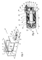
- the loom M represented at figure 1 comprises several frames of smooth, of which only one is shown in this figure with the reference C.
- This frame C is equipped with rails 10 whose respective eyelets 11 are traversed by warp son 12 moving in the direction of the arrow F 1 .
- the frame C is animated by a movement of vertical oscillations in the direction of the double arrow F 2 .
- This movement is controlled by connecting rods, only one of which is visible at figure 1 with the reference 20 which are hitched in the lower part of the frame C and two oscillating levers 22.
- These levers 22 are interconnected by a connecting rod 24, while one of the levers 22 is connected by a connecting rod 26 to a crank pin 28 mounted on a drive shaft 30 constituting the output member of an electric rotary actuator 40.
- This actuator 40 is mounted on a support plate 80.
- the plate In practice, and as shown in phantom with the figures 1 and 2 , the plate is provided wide enough to allow it to support one or more other actuators 40 'of the type of the actuator 40.
- the number of actuators 40 is adapted according to the number of C frames to be driven.
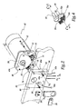
- the actuator 40 is provided with two orifices, only one of which is visible at the figure 2 with the reference 41, which are aligned with orifices 81 provided on the plate 80, which allows the passage of fixing screws of which only one is visible with the reference 43, the second being identified by its X axis line 43 .
- Nuts 43a are provided for immobilize the screws 43 and equivalents in the orifices 41 and 81.
- the actuator 40 comprises a body 42 elongate in a direction AA 'corresponding to an axis of rotation of a rotor 44 belonging to an electric motor 46.
- the rotor 44 forms the output shaft of the motor 46.
- the motor stator 46 the stator being arranged radially around the main part of the rotor 44.
- the rotor 44 is supported relative to the body 42 through bearings 44 a and 44 b.
- the rotor With respect to the middle portion of the rotor 44 located between the bearings, the rotor extends to the level of a brake system 50 electrically controlled and known per se.
- the rotor 44 is integral with a gear 52.
- the pinion 52 may be attached to the rotor 44.
- This pinion 52 is provided with an external toothing 52 is adapted to cooperate with an internal toothing 54 has a hollow wheel 54 which is integral with the drive shaft 30.
- the teeth 54 a is formed on the inner radial surface of a sector 54 b fixed to the main part 54 c of the wheel 54 by means of screws, of which only one is visible in the figure 3 , with the reference 55.
- the hollow wheel 54 could be attached to the shaft 30 and assembled thereto by any suitable means.
- the sector 54 b could be monobloc with the main part 54 c .
- Bearings 30a and 30b support the shaft 30 and the ring gear 54 relative to the remainder of the actuator 40.
- the elements 52 and 54 are disposed within a housing 56 closed by a cover 58, so that it is formed between the bearing 44b and the cover 58, an enclosed volume 56 wherein V is selected trapped a lubricant, such as oil, and in which the elements 52 and 54 constitute a reduction gear 60 of the oscillating rotary movement of the rotor 44, which makes it possible to control the oscillating rotary motion of the shaft 30 and thereby , that of the rocking levers 22 and the oscillating movement of the frame C in the direction of the double arrow F 2 .
- the oscillating rotary movement F 3 of the rotor 44 is transmitted, thanks to the members 52 and 54, to the shaft 30 which is thus driven by a movement of the same nature F 4 .
- This movement is transmitted by the crankpin 28 to the rod 26 which has a movement F 5 itself transmitted by the levers 22 and the rods 20 and 26 to the frame C which has the movement F 2 .
- the amplitude and the speed of the movement F 2 are easily adjustable by varying the amplitude and the speed of the movement F 3 .
- the actuator 40 is provided at this face 40a with a connector 72 intended to allow the connection of the actuator 40 to a connector 82 of corresponding shape carried by the plate 80 and connected to a supply line 82a. electrical current of the actuator 40.
- the connector 82 is provided on the face 80a of the plate 80 against which bears the face 40a when the actuator is mounted on the plate.
- the actuator 40 is equipped with a second connector 74 intended to be connected to a connector 84 of corresponding shape, also provided on the face 80a of the plate 80.
- the connector 84 is connected by a line 84a to unrepresented means for controlling / controlling the actuator 40.
- the connectors 72 and 74 are sufficiently distant from each other to avoid any risk of disturbance.
- the connectors 72 and 74 could be grouped together as a single connector, some of the conducting wires being then shielded to avoid disturbances.
- the plate 80 is provided with an orifice 85 for the passage of the end of the shaft 30 on which the crankpin 28 is mounted.
- a coolant circulation circuit 46a is provided in the housing 42, in particular between the stator 48 and the body 42.
- the number of actuators can be easily and quickly adapted to the number of frames to train. Similarly, the maintenance operations are facilitated, including the standard exchange of one or more actuators.
Landscapes
- Engineering & Computer Science (AREA)
- Textile Engineering (AREA)
- Looms (AREA)
Claims (9)
- Vorrichtung zur Fachbildung für eine Webmaschine (M), die mit mindestens einem Webschaft (C) ausgerüstet ist, der von einem Zugsystem betätigt wird, das für den oder jeden Webschaft mindestens eine Stange (20, 24, 26) zur Übertragung einer Antriebsbewegung (F3), die von einem elektrischen Betätigungselement mit oszillierender Drehbewegung erzeugt wird, einschließt, dadurch gekennzeichnet, dass das Betätigungselement eine unabhängige Anordnung (40) umfasst, die einen elektrischen Motor (46) und ein Hohlradgetriebe (54, 60) einschließt, wobei die Ausgangswelle (44) des Motors mit einem Zahnrad (52) im Eingriff mit einer Innenverzahnung (54a) des Hohlrades ausgerüstet ist, wobei das Hohlrad geeignet ist, eine Antriebswelle (30) der Stange (20, 24, 26) mit einer oszillierenden Drehbewegung (F4) zur Drehung anzutreiben.
- Vorrichtung nach Anspruch 1, dadurch gekennzeichnet, dass das Getriebe (60) in einem Gehäuse (54) gebildet ist, das an einem Ende (44d) des Motors (46) angeordnet ist, wobei das Gehäuse geschlossen (58) ist und das Zahnrad (52), das Hohlrad (54) und ein Schmiermittel enthält.
- Vorrichtung nach einem der vorhergehenden Ansprüche, dadurch gekennzeichnet, dass das Betätigungselement mit einer Bremse (50) ausgerüstet ist.
- Vorrichtung nach einem der vorhergehenden Ansprüche, dadurch gekennzeichnet, dass die Antriebswelle (30) mit der Stange (20, 24, 26) über einen drehfest an der Welle befestigten Zapfen (28) verbunden ist.
- Vorrichtung nach einem der vorhergehenden Ansprüche, dadurch gekennzeichnet, dass das Betätigungselement (40) auf einer selben Endfläche (40a) mit ersten Mitteln (72) zum Verbinden mit einem elektrischen Schaltkreis (82a) für die Energieversorgung und mit zweiten Mitteln (74) zum Verbinden mit einem elektrischen Schaltkreis (84a) zur Überwachung/Steuerung des Betätigungselements ausgerüstet ist.
- Vorrichtung nach Anspruch 5, dadurch gekennzeichnet, dass das Betätigungselement (40) auf derselben Endfläche (40a) mit Mitteln (76, 78) für den Anschluss an einen Zirkulationskreis (86, 88; F6, F7) für ein Kühlfluid ausgerüstet ist.
- Vorrichtung nach einem der Ansprüche 5 oder 6, dadurch gekennzeichnet, dass die Endfläche (40a) des Betätigungselements (40), auf der die Mittel zum Verbinden (72, 74) und gegebenenfalls die Anschlussmittel (76, 78) vorgesehen sind, diejenige ist, von der die Antriebswelle (30) hervor ragt.
- Vorrichtung nach einem der Ansprüche 5 bis 7, dadurch gekennzeichnet, dass das Betätigungselement (40) geeignet ist, an einem Träger (80) montiert zu werden, der mit komplementären Mitteln (82, 84, 86, 88) zu den Mitteln zum Verbinden (72, 74) und gegebenenfalls den Anschlussmitteln (76, 78) versehen ist, wobei die Antriebswelle (30) geeignet ist, den Träger zu durchqueren (bei 85), wenn das Betätigungselement an dem Träger befestigt ist.
- Webmaschine (M), ausgerüstet mit einer Fachbildungsvorrichtung (C, 10-88) nach einem der vorhergehenden Ansprüche.
Applications Claiming Priority (2)
| Application Number | Priority Date | Filing Date | Title |
|---|---|---|---|
| FR0307407A FR2856412B1 (fr) | 2003-06-19 | 2003-06-19 | Dispositif de formation de la foule pour metier a tisser equipe de cadres de lisses, et metier a tisser incorporant un tel dispositif |
| FR0307407 | 2003-06-19 |
Publications (2)
| Publication Number | Publication Date |
|---|---|
| EP1489208A1 EP1489208A1 (de) | 2004-12-22 |
| EP1489208B1 true EP1489208B1 (de) | 2012-05-23 |
Family
ID=33396810
Family Applications (1)
| Application Number | Title | Priority Date | Filing Date |
|---|---|---|---|
| EP20040356106 Expired - Lifetime EP1489208B1 (de) | 2003-06-19 | 2004-06-18 | Fachbildevorrichtung für Webmaschine mit Webschäften und Webmaschine mit einer solchen Vorrichtung |
Country Status (4)
| Country | Link |
|---|---|
| EP (1) | EP1489208B1 (de) |
| JP (1) | JP2005009067A (de) |
| CN (1) | CN100564631C (de) |
| FR (1) | FR2856412B1 (de) |
Families Citing this family (8)
| Publication number | Priority date | Publication date | Assignee | Title |
|---|---|---|---|---|
| BE1016669A3 (nl) * | 2005-07-05 | 2007-04-03 | Wiele Michel Van De Nv | Inrichting voor het aandrijven van een weefraam in een weefmachine, en een weefmachine voorzien van een of meerdere dergelijke inrichtingen. |
| FR2911882B1 (fr) | 2007-01-31 | 2009-05-29 | Staubli Faverges Sca | Dispositif de formation de la foule incorporant des blocs moteurs electriques et metier a tisser equipe d'un tel dispositif. |
| JP5369874B2 (ja) * | 2009-04-28 | 2013-12-18 | 株式会社豊田自動織機 | 経糸開口装置における開口モータ冷却装置 |
| EP2251467B1 (de) | 2009-05-13 | 2013-08-07 | SCHÖNHERR Textilmaschinenbau GmbH | Verfahren zum gleichzeitigen Weben von zwei Gewebe, Gewebe das mit einem solchen Verfahren gewebt wird und Webmaschine bei der dieses Verfahren anwendbar ist. |
| FR2956414B1 (fr) | 2010-02-12 | 2012-03-16 | Staubli Sa Ets | Procede de commande des actionneurs electriques d'un dispositif de formation de la foule |
| FR2962740B1 (fr) * | 2010-07-19 | 2012-08-03 | Staubli Sa Ets | Metier a tisser et procede de controle de la temperature d'un lubrifiant dans un tel metier |
| JP6635006B2 (ja) * | 2016-11-25 | 2020-01-22 | 株式会社豊田自動織機 | 織機における開口方法及び開口装置 |
| FR3126714B1 (fr) * | 2021-09-06 | 2023-09-08 | Staubli Sa Ets | Machine de formation de la foule pour un métier à tisser et son procédé de réglage |
Family Cites Families (7)
| Publication number | Priority date | Publication date | Assignee | Title |
|---|---|---|---|---|
| JPS4915500Y1 (de) * | 1969-05-08 | 1974-04-18 | ||
| JPH0516230Y2 (de) * | 1987-10-30 | 1993-04-28 | ||
| JP3424367B2 (ja) * | 1994-04-06 | 2003-07-07 | 株式会社豊田自動織機 | 織機における開口制御装置 |
| JPH10130985A (ja) * | 1996-10-23 | 1998-05-19 | Toyota Autom Loom Works Ltd | 織機における開口装置 |
| DE19651799A1 (de) * | 1996-12-13 | 1998-06-18 | Schoenherr Webstuhlbau Gmbh | Antriebsvorrichtung für die Fachbildeelemente von Webmaschinen |
| JP3337394B2 (ja) * | 1997-05-27 | 2002-10-21 | 津田駒工業株式会社 | 織機の開口制御方法と、その装置 |
| DE10061717B4 (de) * | 2000-12-12 | 2006-01-26 | Lindauer Dornier Gmbh | Antriebsanordnung für eine Webmaschine und Fachbildemaschine |
-
2003
- 2003-06-19 FR FR0307407A patent/FR2856412B1/fr not_active Expired - Fee Related
-
2004
- 2004-06-15 CN CNB2004100487447A patent/CN100564631C/zh not_active Expired - Fee Related
- 2004-06-18 JP JP2004181372A patent/JP2005009067A/ja active Pending
- 2004-06-18 EP EP20040356106 patent/EP1489208B1/de not_active Expired - Lifetime
Also Published As
| Publication number | Publication date |
|---|---|
| EP1489208A1 (de) | 2004-12-22 |
| JP2005009067A (ja) | 2005-01-13 |
| CN100564631C (zh) | 2009-12-02 |
| CN1572935A (zh) | 2005-02-02 |
| FR2856412A1 (fr) | 2004-12-24 |
| FR2856412B1 (fr) | 2005-07-22 |
Similar Documents
| Publication | Publication Date | Title |
|---|---|---|
| EP1553324B1 (de) | Lagerträger mit doppelter Steifigkeit | |
| EP0224407B1 (de) | Zahnradgetriebe mit einer Antriebswelle und zwei Vorgelegewellen | |
| FR2500688A1 (fr) | Groupe electrique d'entrainement avec poulie supportee par le carter | |
| CA2619927A1 (fr) | Turbopropulseur a helice a pas reglable | |
| FR2580249A1 (fr) | Appareil de direction assistee commande electriquement | |
| EP3719187B1 (de) | Fachbildungsvorrichtung und webmaschine vom typ jacquard, die mit dieser vorrichtung ausgerüstet ist | |
| EP1489208A1 (de) | Fachbildevorrichtung für Webmaschine mit Webschäften und Webmaschine mit einer solchen Vorrichtung | |
| EP1191259B1 (de) | Schmiereinrichtung eines in unterschiedlicher Orientierung ausrichtbaren Leistungsgetriebes, insbesondere für schwenkbare Rotoren eines Flugzeuges | |
| FR2768995A1 (fr) | Resonateur pendulaire de tete de rotor | |
| FR2740853A1 (fr) | Dispositif de lubrification dynamique d'un palier de guidage pour arbre de moteur electrique | |
| FR2613012A1 (fr) | Renvoi d'angle a pignons coniques, notamment pour machines agricoles | |
| EP2723995B1 (de) | Zusätzliches relais mit verlängerter lebensdauer | |
| EP0050891A1 (de) | Windmotor | |
| FR2938713A1 (fr) | Moteur electrique a montage coaxial | |
| EP1386692B1 (de) | Antriebsvorrichtung für Werkzeugmaschinen | |
| FR2568090A1 (fr) | Dispositif d'entrainement d'une barre de coupe de moissonneuses | |
| EP1743058B1 (de) | Höheneinstellvorrichtung, damit ausgerüstete xenterbetätigte harnischeinzugmechanik und damit ausgerüstete webmaschine | |
| FR3020804B1 (fr) | Treuil modulaire embarque | |
| EP0249511B1 (de) | Anzeigeapparat mit Zeiger und Indexierungshülse dafür | |
| EP0082110A1 (de) | Elektronische Uhr mit oder ohne Sekundenzeiger | |
| FR2558556A1 (fr) | Dispositif mecanique de transformation d'un mouvement circulaire a vitesse constante en mouvement circulaire a vitesse variable periodiquement | |
| EP0506500A1 (de) | Vorrichtung zum Umwandeln einer drehenden Bewegung in eine oszillierende Bewegung | |
| FR3159929A1 (fr) | Module motopropulseur de vehicule automobile electrique, et groupe motopropulseur comportant un tel module | |
| EP0121488A1 (de) | Untersetzungsgeriebe, insbesondere für eine Seilschwebebahn oder dergleichen | |
| FR2735200A1 (fr) | Transmission de securite comportant deux helices contra-rotatives |
Legal Events
| Date | Code | Title | Description |
|---|---|---|---|
| PUAI | Public reference made under article 153(3) epc to a published international application that has entered the european phase |
Free format text: ORIGINAL CODE: 0009012 |
|
| AK | Designated contracting states |
Kind code of ref document: A1 Designated state(s): AT BE BG CH CY CZ DE DK EE ES FI FR GB GR HU IE IT LI LU MC NL PL PT RO SE SI SK TR |
|
| AX | Request for extension of the european patent |
Extension state: AL HR LT LV MK |
|
| 17P | Request for examination filed |
Effective date: 20050319 |
|
| AKX | Designation fees paid |
Designated state(s): BE CH DE FR IT LI TR |
|
| GRAP | Despatch of communication of intention to grant a patent |
Free format text: ORIGINAL CODE: EPIDOSNIGR1 |
|
| GRAS | Grant fee paid |
Free format text: ORIGINAL CODE: EPIDOSNIGR3 |
|
| GRAA | (expected) grant |
Free format text: ORIGINAL CODE: 0009210 |
|
| AK | Designated contracting states |
Kind code of ref document: B1 Designated state(s): BE CH DE FR IT LI TR |
|
| REG | Reference to a national code |
Ref country code: CH Ref legal event code: EP |
|
| REG | Reference to a national code |
Ref country code: DE Ref legal event code: R096 Ref document number: 602004037882 Country of ref document: DE Effective date: 20120726 |
|
| PLBE | No opposition filed within time limit |
Free format text: ORIGINAL CODE: 0009261 |
|
| STAA | Information on the status of an ep patent application or granted ep patent |
Free format text: STATUS: NO OPPOSITION FILED WITHIN TIME LIMIT |
|
| 26N | No opposition filed |
Effective date: 20130226 |
|
| REG | Reference to a national code |
Ref country code: DE Ref legal event code: R097 Ref document number: 602004037882 Country of ref document: DE Effective date: 20130226 |
|
| REG | Reference to a national code |
Ref country code: FR Ref legal event code: PLFP Year of fee payment: 13 |
|
| REG | Reference to a national code |
Ref country code: FR Ref legal event code: PLFP Year of fee payment: 14 |
|
| REG | Reference to a national code |
Ref country code: FR Ref legal event code: PLFP Year of fee payment: 15 |
|
| PGFP | Annual fee paid to national office [announced via postgrant information from national office to epo] |
Ref country code: IT Payment date: 20220621 Year of fee payment: 19 |
|
| PGFP | Annual fee paid to national office [announced via postgrant information from national office to epo] |
Ref country code: TR Payment date: 20220609 Year of fee payment: 19 Ref country code: BE Payment date: 20220627 Year of fee payment: 19 |
|
| PGFP | Annual fee paid to national office [announced via postgrant information from national office to epo] |
Ref country code: FR Payment date: 20220627 Year of fee payment: 19 |
|
| PGFP | Annual fee paid to national office [announced via postgrant information from national office to epo] |
Ref country code: DE Payment date: 20220629 Year of fee payment: 19 |
|
| PGFP | Annual fee paid to national office [announced via postgrant information from national office to epo] |
Ref country code: CH Payment date: 20220706 Year of fee payment: 19 |
|
| REG | Reference to a national code |
Ref country code: DE Ref legal event code: R119 Ref document number: 602004037882 Country of ref document: DE |
|
| REG | Reference to a national code |
Ref country code: CH Ref legal event code: PL |
|
| REG | Reference to a national code |
Ref country code: BE Ref legal event code: MM Effective date: 20230630 |
|
| PG25 | Lapsed in a contracting state [announced via postgrant information from national office to epo] |
Ref country code: DE Free format text: LAPSE BECAUSE OF NON-PAYMENT OF DUE FEES Effective date: 20240103 Ref country code: CH Free format text: LAPSE BECAUSE OF NON-PAYMENT OF DUE FEES Effective date: 20230630 |
|
| PG25 | Lapsed in a contracting state [announced via postgrant information from national office to epo] |
Ref country code: FR Free format text: LAPSE BECAUSE OF NON-PAYMENT OF DUE FEES Effective date: 20230630 Ref country code: BE Free format text: LAPSE BECAUSE OF NON-PAYMENT OF DUE FEES Effective date: 20230630 |
|
| PG25 | Lapsed in a contracting state [announced via postgrant information from national office to epo] |
Ref country code: IT Free format text: LAPSE BECAUSE OF NON-PAYMENT OF DUE FEES Effective date: 20230618 |