EP1489213A1 - Vorrichtung zum Beaufschlagen einer Faserbahn mit Wasserstrahlen - Google Patents
Vorrichtung zum Beaufschlagen einer Faserbahn mit Wasserstrahlen Download PDFInfo
- Publication number
- EP1489213A1 EP1489213A1 EP04291113A EP04291113A EP1489213A1 EP 1489213 A1 EP1489213 A1 EP 1489213A1 EP 04291113 A EP04291113 A EP 04291113A EP 04291113 A EP04291113 A EP 04291113A EP 1489213 A1 EP1489213 A1 EP 1489213A1
- Authority
- EP
- European Patent Office
- Prior art keywords
- sleeve
- support cylinder
- intended
- jets
- cylinder
- Prior art date
- Legal status (The legal status is an assumption and is not a legal conclusion. Google has not performed a legal analysis and makes no representation as to the accuracy of the status listed.)
- Withdrawn
Links
- XLYOFNOQVPJJNP-UHFFFAOYSA-N water Substances O XLYOFNOQVPJJNP-UHFFFAOYSA-N 0.000 title claims abstract description 12
- 239000007921 spray Substances 0.000 claims 1
- 229910000906 Bronze Inorganic materials 0.000 abstract description 2
- 239000010974 bronze Substances 0.000 abstract description 2
- KUNSUQLRTQLHQQ-UHFFFAOYSA-N copper tin Chemical compound [Cu].[Sn] KUNSUQLRTQLHQQ-UHFFFAOYSA-N 0.000 abstract description 2
- 239000002184 metal Substances 0.000 abstract description 2
- 239000000284 extract Substances 0.000 abstract 1
- 239000000463 material Substances 0.000 abstract 1
- 229910001220 stainless steel Inorganic materials 0.000 abstract 1
- 239000010935 stainless steel Substances 0.000 abstract 1
- 229910000831 Steel Inorganic materials 0.000 description 1
- 238000005452 bending Methods 0.000 description 1
- 238000006073 displacement reaction Methods 0.000 description 1
- 239000004744 fabric Substances 0.000 description 1
- 238000005461 lubrication Methods 0.000 description 1
- 239000010959 steel Substances 0.000 description 1
- 239000004753 textile Substances 0.000 description 1
Images
Classifications
-
- D—TEXTILES; PAPER
- D04—BRAIDING; LACE-MAKING; KNITTING; TRIMMINGS; NON-WOVEN FABRICS
- D04H—MAKING TEXTILE FABRICS, e.g. FROM FIBRES OR FILAMENTARY MATERIAL; FABRICS MADE BY SUCH PROCESSES OR APPARATUS, e.g. FELTS, NON-WOVEN FABRICS; COTTON-WOOL; WADDING ; NON-WOVEN FABRICS FROM STAPLE FIBRES, FILAMENTS OR YARNS, BONDED WITH AT LEAST ONE WEB-LIKE MATERIAL DURING THEIR CONSOLIDATION
- D04H18/00—Needling machines
- D04H18/04—Needling machines with water jets
Definitions
- the present invention relates to jet projection machines of water on a tablecloth.
- Machines of this kind can be used for produce woven and knitted textile products, especially non woven.
- the machine includes a cylindrical box which has at least one slot extending longitudinally, preferably substantially over the entire generator.
- the interior of the cylindrical body communicates with means of creating a depression.
- Training means lead to a perforated support cylinder surrounding the body at a distance from it.
- a micro-hole sleeve is threaded onto the cylinder and means are provided preventing the sleeve from moving along the cylinder.
- the sleeve is secured in rotation and in translation of the support cylinder by via a screw connection (holding the sleeve from the outside), by a system of inflatable seals (holding the sleeve from the inside).
- a injector projects jets of water under pressure towards the face outside of the sleeve.
- Means are provided for passing a tablecloth on the outside of the sleeve where the water jets are directed there.
- the invention relates to a machine of the type mentioned above in which the life of the sleeve is greater.
- the mounting of the sleeve is simplified and it can be made with larger tolerances inside diameter.
- the sleeve is mounted with the possibility of turning freely on the support cylinder and the means intended to prevent sleeve to move along the support cylinder are means limiting the displacement of the sleeve along the support cylinder, but allowing the rotation of the sleeve on the support cylinder.
- These latter means may be in particular two radial stops fixed to the support cylinder on the one hand and on the other side of the sleeve.
- the vacuum in the cylindrical body is in generally between 50 and 500 millibar.
- the cylindrical box can be in general from 1 to 4 slots which extend over an entire generator.
- the width of the suction slots is general between 5 and 30 mm.
- the support cylinder can be a honeycomb, sheet metal cylinder perforated rolled in perforated tube and the support cylinder can be made of steel stainless, bronze, plastic.
- the sleeve has a percentage of holes which represents from 3% to 25% of its lateral surface. It has a microperforated structure and can be made a thin perforated tube covered with a coarse drainage fabric and a fine surface canvas.
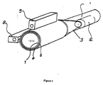
- the machine shown schematically in Figure 1 includes a cylindrical body 1 driven in rotation by a device 2 for driving belt 3.
- a perforated support cylinder 4 surrounds the body 1 while being distance from it and is integral in rotation.
- a 5-hole sleeve is threaded onto the support cylinder 4.
- a pipe 7 for extracting air and water is connected to a vacuum pump and allows the interior of box 1 to be depression.
- Two injectors 8 and 9 send water jets respectively under pressure towards the outer face of the sleeve 5.
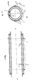
- the body 1 has a slot 10 extending following its lower generator. While the support cylinder 4 is returned integral in rotation with the body 1 by shims 11, the sleeve 5 is mounted free to rotate on the support cylinder 4. The inner face of the sleeve 5 can roll freely on the outside of the support cylinder 4. But as shown in Figure 3, stops 12 fixed to the support cylinder 4 prevent the sleeve 5 from moving along the support cylinder 4. A roller 13 makes it possible to pass a sheet N of nonwoven to be consolidated on the outer face of the sleeve 2 at the point where the water jets are directed there.
Landscapes
- Engineering & Computer Science (AREA)
- Textile Engineering (AREA)
- Treatment Of Fiber Materials (AREA)
- Rolls And Other Rotary Bodies (AREA)
- Perforating, Stamping-Out Or Severing By Means Other Than Cutting (AREA)
Applications Claiming Priority (2)
| Application Number | Priority Date | Filing Date | Title |
|---|---|---|---|
| FR0307335A FR2856413B1 (fr) | 2003-06-18 | 2003-06-18 | Machine de projection de jets d'eau sur une nappe |
| FR0307335 | 2003-06-18 |
Publications (1)
| Publication Number | Publication Date |
|---|---|
| EP1489213A1 true EP1489213A1 (de) | 2004-12-22 |
Family
ID=33396795
Family Applications (1)
| Application Number | Title | Priority Date | Filing Date |
|---|---|---|---|
| EP04291113A Withdrawn EP1489213A1 (de) | 2003-06-18 | 2004-04-30 | Vorrichtung zum Beaufschlagen einer Faserbahn mit Wasserstrahlen |
Country Status (2)
| Country | Link |
|---|---|
| EP (1) | EP1489213A1 (de) |
| FR (1) | FR2856413B1 (de) |
Cited By (3)
| Publication number | Priority date | Publication date | Assignee | Title |
|---|---|---|---|---|
| WO2006087064A1 (de) * | 2005-02-18 | 2006-08-24 | Fleissner Gmbh | Vorrichtung zur musterung und verfestigung einer warenbahn mit austauschbarer musterschale |
| EP1895037A1 (de) * | 2006-08-30 | 2008-03-05 | N.R. Spuntech Industries Ltd. | Zylinderförmige Absaugkastenanordnung |
| CN103541154A (zh) * | 2013-10-30 | 2014-01-29 | 绍兴县庄洁无纺材料有限公司 | 一种湿态纤网主动转移转鼓装置 |
Citations (5)
| Publication number | Priority date | Publication date | Assignee | Title |
|---|---|---|---|---|
| US3679535A (en) * | 1970-03-24 | 1972-07-25 | Johnson & Johnson | Nonwoven fabric comprising discontinuous groups of small holes connected by ribbons defining large holes |
| US3799052A (en) * | 1972-02-05 | 1974-03-26 | Kuesters E | Apparatus for the continuous pressure treatment of a web |
| US5768756A (en) * | 1995-05-17 | 1998-06-23 | Icbt Perfojet | Process and device for manufacturing a non-woven unpatterned textile |
| JP2000160461A (ja) * | 1998-11-27 | 2000-06-13 | Takayuki Mende | 不織布の製造装置における水流交絡装置、および該水流交絡装置を使用する不織布の製造方法 |
| FR2799214A1 (fr) * | 1999-10-05 | 2001-04-06 | Icbt Perfojet Sa | Procede pour la realisation de nappes non tissees dont la cohesion est obtenue par l'action de jets de fluide |
-
2003
- 2003-06-18 FR FR0307335A patent/FR2856413B1/fr not_active Expired - Fee Related
-
2004
- 2004-04-30 EP EP04291113A patent/EP1489213A1/de not_active Withdrawn
Patent Citations (5)
| Publication number | Priority date | Publication date | Assignee | Title |
|---|---|---|---|---|
| US3679535A (en) * | 1970-03-24 | 1972-07-25 | Johnson & Johnson | Nonwoven fabric comprising discontinuous groups of small holes connected by ribbons defining large holes |
| US3799052A (en) * | 1972-02-05 | 1974-03-26 | Kuesters E | Apparatus for the continuous pressure treatment of a web |
| US5768756A (en) * | 1995-05-17 | 1998-06-23 | Icbt Perfojet | Process and device for manufacturing a non-woven unpatterned textile |
| JP2000160461A (ja) * | 1998-11-27 | 2000-06-13 | Takayuki Mende | 不織布の製造装置における水流交絡装置、および該水流交絡装置を使用する不織布の製造方法 |
| FR2799214A1 (fr) * | 1999-10-05 | 2001-04-06 | Icbt Perfojet Sa | Procede pour la realisation de nappes non tissees dont la cohesion est obtenue par l'action de jets de fluide |
Non-Patent Citations (1)
| Title |
|---|
| DATABASE WPI Section Ch Week 200040, Derwent World Patents Index; Class F04, AN 2000-454711, XP002300931 * |
Cited By (6)
| Publication number | Priority date | Publication date | Assignee | Title |
|---|---|---|---|---|
| WO2006087064A1 (de) * | 2005-02-18 | 2006-08-24 | Fleissner Gmbh | Vorrichtung zur musterung und verfestigung einer warenbahn mit austauschbarer musterschale |
| US7448118B2 (en) | 2005-02-18 | 2008-11-11 | Fleissner Gmbh | Apparatus for patterning and stabilizing a workpiece web by use of an replaceable patterning shell |
| CN101120130B (zh) * | 2005-02-18 | 2011-02-23 | 弗莱斯纳有限公司 | 带有可更换模版筒的在环形织物网上形成和固定图案的装置 |
| JP4806420B2 (ja) * | 2005-02-18 | 2011-11-02 | フライスナー・ゲゼルシャフト・ミト・ベシュレンクテル・ハフツング | 交換可能な模様シェル体でもって、製品ウェブを、模様付けおよび固化するための装置 |
| EP1895037A1 (de) * | 2006-08-30 | 2008-03-05 | N.R. Spuntech Industries Ltd. | Zylinderförmige Absaugkastenanordnung |
| CN103541154A (zh) * | 2013-10-30 | 2014-01-29 | 绍兴县庄洁无纺材料有限公司 | 一种湿态纤网主动转移转鼓装置 |
Also Published As
| Publication number | Publication date |
|---|---|
| FR2856413B1 (fr) | 2005-08-19 |
| FR2856413A1 (fr) | 2004-12-24 |
Similar Documents
| Publication | Publication Date | Title |
|---|---|---|
| EP0304882B1 (de) | Maschine zum Elektroerosionsschneiden | |
| FR2484870A1 (fr) | Dispositif de reglage de l'epaisseur d'application lors de l'enduction de bandes de materiau continues | |
| EP2232075A2 (de) | Erweiterte peristaltische pumpe | |
| EP0471596A2 (de) | Dichtungsvorrichtung mit aufblasbarer Dichtung für Türen oder mobile Panele | |
| EP2474488A3 (de) | Reiniger und Spanner für Förderband mit konstantem Winkel und Druck | |
| KR970069241A (ko) | 연마장치 | |
| FR2524100A1 (fr) | Deflecteur d'eau pour palier a pellicule d'huile de laminoir | |
| EP0481157B1 (de) | Stützvorrichtung für die Latten eines Lattenrostes | |
| EP1489213A1 (de) | Vorrichtung zum Beaufschlagen einer Faserbahn mit Wasserstrahlen | |
| KR101705845B1 (ko) | 배관용 스케일 제거장치 | |
| FR2897073A1 (fr) | Appareil dans une machine textile ayant un premier rouleau ou rouleau principal a grande vitesse | |
| KR970061446A (ko) | 분말 비임 가공기의 분말 밀봉 장치 | |
| JP3160397B2 (ja) | 別体をなす外皮及びロールコアを有するロール | |
| WO1995015837A1 (fr) | Machine de decoupe a dispositif de support de la matiere en cours de decoupe, notamment pour la decoupe par jet d'eau | |
| WO2016124485A1 (fr) | Dispositif pour enfiler les gants en matière élastique à usage unique stériles ou non stériles | |
| EP0843122A3 (de) | Schlauchkupplung | |
| EP1394295A2 (de) | Verfahren und Vorrichtung zum Schneiden von Fasern in Stücke | |
| FR3072121B1 (fr) | Dispositif d'etancheite entre rotor et stator de turbomachine | |
| FR2634858A1 (fr) | Embout de raccordement pour tuyaux et appareil pour l'emmanchement de l'embout dans un tuyau | |
| BE523004A (de) | ||
| FR2700531A1 (fr) | Dispositif de traction sur câble. | |
| KR102398752B1 (ko) | 다기능 파이프 피막 제거 장치 | |
| FR2734512A1 (fr) | Encrier d'une machine rotative a imprimer | |
| FR2470528A1 (fr) | Couteau de faucheuse | |
| KR20010099804A (ko) | 밀봉 수단을 가진 기계 장치 및 밀봉 수단을 장착하는 방법 |
Legal Events
| Date | Code | Title | Description |
|---|---|---|---|
| PUAI | Public reference made under article 153(3) epc to a published international application that has entered the european phase |
Free format text: ORIGINAL CODE: 0009012 |
|
| AK | Designated contracting states |
Kind code of ref document: A1 Designated state(s): AT BE BG CH CY CZ DE DK EE ES FI FR GB GR HU IE IT LI LU MC NL PL PT RO SE SI SK TR |
|
| AX | Request for extension of the european patent |
Extension state: AL HR LT LV MK |
|
| 17P | Request for examination filed |
Effective date: 20050622 |
|
| AKX | Designation fees paid |
Designated state(s): AT BE BG CH CY CZ DE DK EE ES FI FR GB GR HU IE IT LI LU MC NL PL PT RO SE SI SK TR |
|
| STAA | Information on the status of an ep patent application or granted ep patent |
Free format text: STATUS: THE APPLICATION HAS BEEN WITHDRAWN |
|
| 18W | Application withdrawn |
Effective date: 20051128 |