EP1489215A2 - Vorrichtung zum Färben oder Bleichen von Garnspulen - Google Patents
Vorrichtung zum Färben oder Bleichen von Garnspulen Download PDFInfo
- Publication number
- EP1489215A2 EP1489215A2 EP04076647A EP04076647A EP1489215A2 EP 1489215 A2 EP1489215 A2 EP 1489215A2 EP 04076647 A EP04076647 A EP 04076647A EP 04076647 A EP04076647 A EP 04076647A EP 1489215 A2 EP1489215 A2 EP 1489215A2
- Authority
- EP
- European Patent Office
- Prior art keywords
- treatment
- small
- boilers
- bath
- circulation
- Prior art date
- Legal status (The legal status is an assumption and is not a legal conclusion. Google has not performed a legal analysis and makes no representation as to the accuracy of the status listed.)
- Withdrawn
Links
Images






Classifications
-
- D—TEXTILES; PAPER
- D06—TREATMENT OF TEXTILES OR THE LIKE; LAUNDERING; FLEXIBLE MATERIALS NOT OTHERWISE PROVIDED FOR
- D06B—TREATING TEXTILE MATERIALS USING LIQUIDS, GASES OR VAPOURS
- D06B5/00—Forcing liquids, gases or vapours through textile materials to effect treatment, e.g. washing, dyeing, bleaching, sizing impregnating
- D06B5/12—Forcing liquids, gases or vapours through textile materials to effect treatment, e.g. washing, dyeing, bleaching, sizing impregnating through materials of definite length
- D06B5/16—Forcing liquids, gases or vapours through textile materials to effect treatment, e.g. washing, dyeing, bleaching, sizing impregnating through materials of definite length through yarns, threads or filaments
-
- D—TEXTILES; PAPER
- D06—TREATMENT OF TEXTILES OR THE LIKE; LAUNDERING; FLEXIBLE MATERIALS NOT OTHERWISE PROVIDED FOR
- D06B—TREATING TEXTILE MATERIALS USING LIQUIDS, GASES OR VAPOURS
- D06B15/00—Removing liquids, gases or vapours from textile materials in association with treatment of the materials by liquids, gases or vapours
- D06B15/10—Removing liquids, gases or vapours from textile materials in association with treatment of the materials by liquids, gases or vapours by use of centrifugal force
-
- D—TEXTILES; PAPER
- D06—TREATMENT OF TEXTILES OR THE LIKE; LAUNDERING; FLEXIBLE MATERIALS NOT OTHERWISE PROVIDED FOR
- D06B—TREATING TEXTILE MATERIALS USING LIQUIDS, GASES OR VAPOURS
- D06B21/00—Successive treatments of textile materials by liquids, gases or vapours
-
- D—TEXTILES; PAPER
- D06—TREATMENT OF TEXTILES OR THE LIKE; LAUNDERING; FLEXIBLE MATERIALS NOT OTHERWISE PROVIDED FOR
- D06B—TREATING TEXTILE MATERIALS USING LIQUIDS, GASES OR VAPOURS
- D06B23/00—Component parts, details, or accessories of apparatus or machines, specially adapted for the treating of textile materials, not restricted to a particular kind of apparatus, provided for in groups D06B1/00 - D06B21/00
- D06B23/04—Carriers or supports for textile materials to be treated
Definitions
- the present invention refers to a dyeing or bleaching apparatus of yarns wound on reels or similar packages.
- Conventional apparatuses for dyeing or bleaching yarns consist of a vertical or horizontal treatment boiler that is cylindrical in shape with a curved base and lid, equipped with a pump and with devices for the reversible circulation of a treatment bath.
- Such apparatuses have universal use since they are suitable for receiving material-holders for the different possible packages of yarn.
- These apparatuses work with a relatively high bath ratio, in other words they use a large amount of water for every kg of material to be treated, for every dyeing cycle and, moreover, the number of water changes varies according to the type of material to be treated and the class of colorants used.
- patent application WO 02/095113 describes an externally cylindrical treatment boiler with an annular section, in other words without upper and lower rounded portions
- application WO 02/095114 describes a plurality of distinct small treatment boilers arranged on a single circumference each suitable for receiving a mobile reel-holding shaft that can be withdrawn at the same time as the others for the subsequent centrifugal water-removal and drying operations.
- the purpose of the present invention is that of realising a dyeing or bleaching apparatus that allows good fractionability of use, maintaining a constant bath ratio at the type and load of material to be treated varies, without reducing the productivity of the apparatus.
- Another purpose of the present invention is that of realising a dyeing or bleaching apparatus that uses a very low bath ratio, consequently reducing the environmental and atmospheric pollution and the production and energy costs.
- Yet another purpose of the present invention is that of realising a dyeing or bleaching apparatus of yarns wound on reels or similar packages that allows the manipulations to be carried out to be minimised as much as possible.
- a further purpose of the present invention is that of realising a dyeing or bleaching apparatus that is particularly simple and functional, with low costs.
- a dyeing apparatus is shown, with a low bath ratio, equipped with a plurality of vertical small boilers 15, wholly indicated with 10.
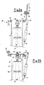
- Such an apparatus 10 comprises a cylindrical structure 65 with a vertical axis.
- a lower ring 66 and an upper ring 67 are internally welded, suitably spaced apart, onto such a structure 65, which support a plurality of small cylindrical treatment boilers 15 with a vertical axis, the axes of which are arranged on a single circumference inside the structure 65, concentric with its axis, as shall be seen in figure 7.
- the small cylindrical boilers 15 are equipped with a flat base 48 and are open at the top. They are closed through a series of circular lids 11, each fitted to its own small boiler, and arranged with the centres on a single circumference. Such a circumference is the same as the one on which the axes of the small boilers 15 are arranged.
- Each lid 11 is supported at an end thereof by a lever 51, pivoted with a pin 43 to the small boiler 15.
- Each lever 51 is actuated by a reversal cylinder 20, arranged between an end of the lever 51 and a bracket 21 foreseen on the outside of the small boiler 15.
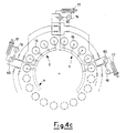
- the small boilers 15, with reference to figure 4a, are placed in communication by two fluid connectors 56, 57 so as to form two independent treatment sectors 2, 2'.
- each sector 2, 2' consists of a predetermined number of small boilers 15, for example ten in figure 4a, fluidly connected so as to be able to treat the reels of yarn 12 contained in the sector, thus formed, independently of the reels of yarn 12 contained in the remaining sector. It is thus possible, for example, to treat the reels of sector 2 with one type of colour and the reels of sector 2' with another type of colour, without reducing the productivity of the apparatus.
- each small boiler 15 is equipped with two entry and/or exit tubes 18, 19 of the treatment bath connected to the two fluid connectors 56, 57.
- These connectors 56, 57 are represented by the four connection ducts 61, 62, 63, 64.
- Each sector 2, 2' is connected to a dedicated circulation group of the treatment bath 90, 91.
- Each circulation group 90, 91 of the bath as shown in figure 4a, comprises an external pump 16, a heat exchanger 17 for cooling and heating the bath and a flow-inverter 60.
- Interconnection means such as interconnection ducts 66, 67, are also foreseen, suitable for putting two or more distinct sectors in communication.
- the interconnection ducts 66, 67 are equipped with selection means, such as intercept valves 68, 69, 70, 71, 72, 73, to open or close the circulation of the bath.
- each small boiler 15 is equipped centrally with a catch basin 49.
- the catch basin at a lower end, is connected to the piping 18. On the other end, however, it terminates with an upturned reel-shaped seat 25'.
- Such seats host a conical lower end 25, visible in figure 2, of reel-holding shafts 13, on which the reels 12 to be treated are slotted.
- the reels 12 are, in a known way, wound on conical perforated supports and are separated by spacer discs 26.
- the discs 26 can also be omitted.
- a circular moving device 14 for all of the shafts 13 arranged circumferentially comprising a structure 32 that carries, arranged along the circumference, a plurality of chain portions 33, in particular one for each reel-holding shaft 13, provided at one end with hooks 28 or other known reversible connection means able to be impregnated in suitable slots 27 to connect or release the shafts 13.
- Such devices consist of a pin 30, equipped with a spring 31, able to slide inside a seat 29 formed in the lid 11.
- the pin 30 terminates with a head 32 equipped, on the outside, in other words on the side next to the inside of the boiler 15, with a concave profile, suitable for receiving the shaft 13 that terminates at the top with a chamfer 24.
- FIG 4a a circulation plan of the treatment bath is shown, with the small boilers 15 grouped together by the fluid connection ducts 61-64 to form two distinct treatment sectors 2, 2' .
- connection ducts 61, 62 connect ten small boilers 15 to the circulation group of the treatment bath 90, forming the treatment sector 2
- connection ducts 63, 64 connect the remaining ten small boilers to the circulation group of the bath 91, forming the treatment sector 2'.
- the interconnection ducts 66, 67 connect the two sectors 2, 2' together allowing the exchange of the treatment bath and the valves 68, 69, 70, 71, 72, 73 regulate the opening or closing of the interconnection ducts 66, 67.
- valves 68, 69, 72, 73 and open the valves 70, 71 to make the two sectors 2, 2' work independently or vice-versa to open the valves 68, 69, 72, 73 and close the valves 70, 71 to make the two sectors 2, 2' work in an integrated manner, thus making the same treatment bath circulate in both of the sectors, according to the direction indicated, for example, by the arrows F in figure 4a.
- FIG 4b an alternative circulation plan of the treatment bath of the apparatus according to the invention is shown, in which the small boilers 15 are divided by the fluid connector ducts 74-81, so as to form four distinct treatment sectors 2, 3, 4, 5.
- intercept valves 100-116 regulate the various operating possibilities of the sectors.
- FIG 4c a further alternative circulation plan of the treatment bath is shown, in which the small boilers 15 are grouped together by the fluid connectors to form a plurality of distinct treatment sectors 2, 3, n.
- the structure and operation of this embodiment are totally analogous to that of figures 4a and 4b apart from for the number of treatment sectors, for that of the groups, of the valves and of the ducts and therefore they shall not be described in further detail.
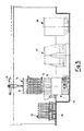
- a dyeing line is shown, under a bridge crane 35, consisting of a trolley 36 that carries a series of shafts 13, arranged on a circumference, the dyeing apparatus 10, a centrifugal water-removal apparatus with baskets having pits or perforated tubes 37 and a drier with a chamber having a circular section 38.
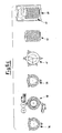
- FIGS. 6a, 6b and 6c other embodiments of the dyeing line are shown, in which there are, in addition with respect to figure 5, a conventional drier with a chamber having a rectangular section 40, a conventional water-removal apparatus 41, and a rectangular trolley 42 that carries a series of fixed shafts.
- the reels 12 to be dyed, wound on the conical perforated supports, are slotted into the shafts 13, separated by discs 26. These shafts 13 are positioned on the trolley 36 to then, all together, through the device 14, be loaded into the dying apparatus 10.
- said shafts 13 are positioned in the small boilers 15, which, as can be seen in figure 1, have an internal diameter slightly greater than the maximum diameter of the reels 12.
- the seats 25' are sized to receive the conical lower ends 25 of the shafts 13.
- the shafts 13, in the example of the figure there are twenty, can be positioned simultaneously, to fill all of the small boilers 15, using the moving device 14.
- the device 14 connects all of the shafts 13 arranged circumferentially for example on the trolley 36, on the same circumference as that which passes through the centre of the small boilers 15, and lowers them from above into the dyeing apparatus through the bridge crane 35.
- the cylinder 20 actuates a flipping of the lever 51 about the pin 43, in a position indicated in figure 3a.
- the mechanical and hermetic closing of the small boilers 15 is carried out by locking the single lids 11 to the upper edges 44 through locking devices 42 or other known systems.
- threaded stay rods pivoted at an end of the small boilers 15 and provided with nuts that can be impregnated in suitable grooves in the lid 11 are used as locking means 42.
- valves 68, 69, 72, 73 are closed preventing access to the interconnection ducts 66, 67, and the valves 70, 71 are opened.
- the small boilers 15 are then filled with two distinct treatment baths.
- valves 70, 71 are closed and the valves 68, 69, 72, 73 are opened, freeing the access of the treatment bath to the interconnection ducts 66, 67.
- the dyeing bath is heated or cooled through the heat exchangers 17.
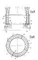
- FIGs 8 and 9 illustrate an alternative embodiment of the apparatus according to the present invention totally similar to the one illustrated in figure 1 apart from the fact that the small treatment boilers 15 are obtained by dividing a boiler formed from two concentric cylinders, like the one illustrated in patent application WO 02/095113, into different treatment sectors 2, 3, 4, 5, through watertight bulkheads 117.
- Each treatment sector is thus formed from a small boiler 15 that has a circular arc of crown section.
- Each sector or small boiler 15 has two entry/exit treatment tubes 18, 19 connected to a dedicated circulation group of the treatment fluid.
- each small boiler or sector has an inner fluid connector 58 shaped to support more reel-holding shafts 13.
- figure 5 and figure 6a represent a dyeing line that foresees a trolley 36 where the shafts 13 are arranged circumferentially with the reels 12 to be treated. These shafts 13 are picked up by the bridge crane 35 which lowers them, through the moving device 14, into the dyeing apparatus 10.
- the series of shafts 13 is picked up by the moving device 14 and lowered into the centrifugal water-removal apparatus 37, which can be with baskets having pits or with perforated tubes, of a suitable size to host the circumferential series of shafts 13.
- the moving device 14 picks up the series of shafts 13 and lowers them into the drier 38, which has a chamber having a circular section of a size suitable for hosting the circumferential series of shafts 13, where the process is completed.
- the productive line includes, with respect to figure 6a, replacing the drier with a chamber having a circular section 38, a conventional drier 40 with a chamber having a rectangular section, for which reason, at the exit from the centrifugal water-removal apparatus 37, the circumferential series of shafts 13 is picked up by the moving device 14 and rested upon a trolley 36, which is then taken into the drier 40.
- the productive line includes, with respect to figure 6a, a conventional water-removal apparatus 41 and a conventional drier 40 with a chamber having a rectangular section, for which reason, at the exit from the dyeing apparatus 10, the circumferential series of shafts 13 is picked up by the moving device 14 and rested upon a trolley 36. From the trolley 36, the single reels 12 are unslotted from the shafts 13 and positioned, manually or mechanically, in the conventional water-removal apparatus 41. At the end of the water-removal step, the single reels 12 are picked up and arranged, manually or mechanically, on a trolley 42, which is then taken into the conventional drier 40 with a chamber having a rectangular section, to conclude the working process.
- a further advantage is the rationalisation of production, since the manual transfer operations of the reels from the dyeing apparatus to the water-removal apparatus, and from here to the drier are eliminated. In practice, therefore, the entire batch is dyed, centrifuged and dried without intermediate manipulations of the reels.
- the apparatus according to the present invention is fractionable into various sectors each of which is equipped with its own circulation group of the dyeing bath.
- Each sector being able to be used independently with a specific dyeing bath totally different with respect to those used in the remaining sectors, or alternatively, being able to be used connected, through the interconnection ducts and the intercept valves, to the remaining sectors for individual dyeing.
- the productivity of the apparatus 10 remains constant at the maximum value, thus allowing the costs to be optimised.
- the apparatus also with the use of one or more partially empty sectors, or rather with the replacement of some reel-holding shafts with bath reducer chambers, in such a way allowing the maximum production capacity to be further fractioned, to the slight detriment to productivity: the operative flexibility is thus maximum.
- apparatuses can be realised with a modular structure, combining or twinning many dyeing apparatuses according to the present invention.
- the reduction in bath ratio permitted by the particular configuration of the small boilers of the apparatus according to the invention leads to the simultaneous decrease in water, energy, steam and chemical product consumption and in environmental and atmospheric polluting discharges.
- the treatment time is reduced since, with the same flow rate of the pump and heat exchange surface with respect to conventional apparatuses, due to the substantial reduction in volume of the bath, increasing its recycles per minute as well as the upward temperature gradient, and thus in theory, and compatibly with the characteristic colorant depletion curves, the treatment time is reduced. Moreover, the increase in cycles per minute also involves an improvement of the dyeing capacity.
- the dyeing apparatus thus conceived is susceptible to modifications and variants, all of which are covered by the invention; moreover, all of the details can be replaced with technically equivalent elements.
- the materials used, as well as the sizes, can be whatever according to the technical requirements.
Landscapes
- Engineering & Computer Science (AREA)
- Chemical & Material Sciences (AREA)
- Materials Engineering (AREA)
- Textile Engineering (AREA)
- Treatment Of Fiber Materials (AREA)
Applications Claiming Priority (2)
| Application Number | Priority Date | Filing Date | Title |
|---|---|---|---|
| ITMI20031209 | 2003-06-16 | ||
| IT001209A ITMI20031209A1 (it) | 2003-06-16 | 2003-06-16 | Apparecchio di tintura o candeggio di filati avvolti |
Publications (2)
| Publication Number | Publication Date |
|---|---|
| EP1489215A2 true EP1489215A2 (de) | 2004-12-22 |
| EP1489215A3 EP1489215A3 (de) | 2005-09-21 |
Family
ID=30131218
Family Applications (1)
| Application Number | Title | Priority Date | Filing Date |
|---|---|---|---|
| EP04076647A Withdrawn EP1489215A3 (de) | 2003-06-16 | 2004-06-04 | Vorrichtung zum Färben oder Bleichen von Garnspulen |
Country Status (5)
| Country | Link |
|---|---|
| US (1) | US20040250575A1 (de) |
| EP (1) | EP1489215A3 (de) |
| CN (1) | CN1572951A (de) |
| BR (1) | BRPI0402218A (de) |
| IT (1) | ITMI20031209A1 (de) |
Cited By (4)
| Publication number | Priority date | Publication date | Assignee | Title |
|---|---|---|---|---|
| GB2404199B (en) * | 2003-07-25 | 2007-07-04 | Falmer Investment Ltd | Textile processing system |
| ITBG20110009A1 (it) * | 2011-04-01 | 2012-10-02 | Enea Pressato | Dispositivo per la mercerizzazione e la tintura di filati roccati |
| CN102776736A (zh) * | 2012-07-30 | 2012-11-14 | 无锡市万邦机械制造厂 | 高温高压染色机 |
| CN101503851B (zh) * | 2009-03-09 | 2013-06-05 | 浙江厚源纺织股份有限公司 | 浸淋交替式绞纱染色方法 |
Families Citing this family (4)
| Publication number | Priority date | Publication date | Assignee | Title |
|---|---|---|---|---|
| IT1393513B1 (it) * | 2009-03-27 | 2012-04-27 | Tecnorama Srl | Apparecchiatura e procedimento per eseguire letture ottiche su materiali tessili confezionati sottoposti a tintura. |
| CN102134793B (zh) * | 2011-04-15 | 2012-05-23 | 广州番禺高勋染整设备制造有限公司 | 超低浴比三级叶轮泵染纱机 |
| CN102583045A (zh) * | 2012-03-08 | 2012-07-18 | 机械科学研究总院先进制造技术研究中心 | 纱笼运送设备 |
| CN109972322B (zh) * | 2019-03-30 | 2021-06-08 | 安徽咏鹅家纺股份有限公司 | 一种纺纱纱线快速漂白装置 |
Family Cites Families (19)
| Publication number | Priority date | Publication date | Assignee | Title |
|---|---|---|---|---|
| US362620A (en) * | 1887-05-10 | hauschel | ||
| US1327662A (en) * | 1920-01-13 | Dyeing-machine | ||
| US2736184A (en) * | 1956-02-28 | harvey | ||
| US708808A (en) * | 1901-12-14 | 1902-09-09 | Charles M Hanson | Apparatus for dyeing slivers. |
| US1174662A (en) * | 1913-02-12 | 1916-03-07 | John Brandwood | Apparatus for the fluid treatment of textile materials. |
| US1173160A (en) * | 1914-11-10 | 1916-02-29 | Samuel Barker | Bleaching-machine. |
| GB542503A (en) * | 1940-07-10 | 1942-01-13 | William Ivan Taylor | Improvements in or relating to apparatus for the treatment of yarn packages |
| US2350191A (en) * | 1941-01-14 | 1944-05-30 | Atlantic Rayon Corp | Dyeing apparatus |
| GB1053944A (de) * | 1966-06-13 | |||
| SE323346B (de) * | 1969-01-14 | 1970-05-04 | Svensson L Ab | |
| GB1290333A (de) * | 1969-01-15 | 1972-09-27 | ||
| CH535610A (de) * | 1971-08-17 | 1973-04-15 | Frauchiger Ag Maschinenfabrik | Einrichtung zum Nassbehandeln von Textilware |
| JPS5523949B2 (de) * | 1972-12-29 | 1980-06-26 | ||
| US4079603A (en) * | 1973-10-16 | 1978-03-21 | Niels Bergholtz & Company K/B | Apparatus for liquid treatment, particularly for textile material dyeing |
| JPH01282380A (ja) * | 1988-05-06 | 1989-11-14 | Hisaka Works Ltd | 連結式パッケージ染色装置 |
| US6405568B1 (en) * | 1997-09-26 | 2002-06-18 | Loris Bellini S.P.A. | Plant for processing yarn on reels |
| US6213620B1 (en) * | 1999-06-24 | 2001-04-10 | Sunny (En-Liung) Huang | Assembled opener with an illumination device |
| ITMI20011116A1 (it) * | 2001-05-25 | 2002-11-25 | Master S A S Di Ronchi Frances | Apparecchio per tintura o candeggio di filati avvolti su rocche o confezioni similari |
| ITMI20011115A1 (it) * | 2001-05-25 | 2002-11-25 | Master S A S Di Ronchi Frances | Apparecchio di tintura o candeggio di filati avvolti su rocche o confezioni similari |
-
2003
- 2003-06-16 IT IT001209A patent/ITMI20031209A1/it unknown
-
2004
- 2004-06-04 US US10/861,160 patent/US20040250575A1/en not_active Abandoned
- 2004-06-04 EP EP04076647A patent/EP1489215A3/de not_active Withdrawn
- 2004-06-14 BR BR0402218-1A patent/BRPI0402218A/pt not_active IP Right Cessation
- 2004-06-16 CN CNA2004100592848A patent/CN1572951A/zh active Pending
Cited By (4)
| Publication number | Priority date | Publication date | Assignee | Title |
|---|---|---|---|---|
| GB2404199B (en) * | 2003-07-25 | 2007-07-04 | Falmer Investment Ltd | Textile processing system |
| CN101503851B (zh) * | 2009-03-09 | 2013-06-05 | 浙江厚源纺织股份有限公司 | 浸淋交替式绞纱染色方法 |
| ITBG20110009A1 (it) * | 2011-04-01 | 2012-10-02 | Enea Pressato | Dispositivo per la mercerizzazione e la tintura di filati roccati |
| CN102776736A (zh) * | 2012-07-30 | 2012-11-14 | 无锡市万邦机械制造厂 | 高温高压染色机 |
Also Published As
| Publication number | Publication date |
|---|---|
| US20040250575A1 (en) | 2004-12-16 |
| EP1489215A3 (de) | 2005-09-21 |
| ITMI20031209A0 (it) | 2003-06-16 |
| ITMI20031209A1 (it) | 2004-12-17 |
| CN1572951A (zh) | 2005-02-02 |
| BRPI0402218A (pt) | 2005-01-25 |
Similar Documents
| Publication | Publication Date | Title |
|---|---|---|
| EP1489215A2 (de) | Vorrichtung zum Färben oder Bleichen von Garnspulen | |
| EP1390575B9 (de) | Färbe- oder bleichapparat für garn auf wickelkörpern | |
| EP1990455B1 (de) | Färbemaschine für Musterpackungen | |
| US4545135A (en) | Installations for spin-drying fibrous or porous materials | |
| CN100476057C (zh) | 一种集成式染料染色釜 | |
| EP1390574B1 (de) | Vorrichtung zum färben oder bleichen von garnspulen oder dergleichen | |
| KR101305363B1 (ko) | 균일가열을 위한 내부가열수단이 구비된 당화 솥 | |
| US5907961A (en) | Textile wet processing apparatus | |
| HK1074064A (en) | Dyeing or bleaching apparatus for yarn packages | |
| CN109082793A (zh) | 筒纱染色机 | |
| CN211498144U (zh) | 一种羊毛衫成衣高效染色装置 | |
| US5323629A (en) | Apparatus and method for treatment of yarn in package form | |
| HK1064134B (en) | Dyeing or bleaching apparatus for yarn wound on reels or similar packages | |
| WO2022229759A1 (en) | Plant for the environmentally sustainable dyeing of spooled yarn and similar textile products, textile staple fibres and various articles with indigo and other reducing dyes | |
| HK1064135B (en) | Dying or bleaching apparatus for yarn wound on reels or similar packages | |
| US4484461A (en) | Dye machine with capacity decreasing insert | |
| US6233982B1 (en) | Method and device for the treatment of ready-to-wear, textile apparel parts | |
| CN114836922B (zh) | 一种针织袜制备用染色装置及其染色方法 | |
| US3785180A (en) | Dyeing apparatus | |
| US3880583A (en) | Method for dyeing textiles | |
| EP0621913B1 (de) | Verfahren und vorrichtung zum färben von textilen waren | |
| CN203420113U (zh) | 立缸染色机 | |
| US3295340A (en) | Dyeing apparatus | |
| EP1561850A1 (de) | Völlig automatisiertes Garnfärbsystem | |
| CN121295457A (zh) | 一种色纺纱染色装置及其使用方法 |
Legal Events
| Date | Code | Title | Description |
|---|---|---|---|
| PUAI | Public reference made under article 153(3) epc to a published international application that has entered the european phase |
Free format text: ORIGINAL CODE: 0009012 |
|
| AK | Designated contracting states |
Kind code of ref document: A2 Designated state(s): AT BE BG CH CY CZ DE DK EE ES FI FR GB GR HU IE IT LI LU MC NL PL PT RO SE SI SK TR |
|
| AX | Request for extension of the european patent |
Extension state: AL HR LT LV MK |
|
| PUAL | Search report despatched |
Free format text: ORIGINAL CODE: 0009013 |
|
| AK | Designated contracting states |
Kind code of ref document: A3 Designated state(s): AT BE BG CH CY CZ DE DK EE ES FI FR GB GR HU IE IT LI LU MC NL PL PT RO SE SI SK TR |
|
| AX | Request for extension of the european patent |
Extension state: AL HR LT LV MK |
|
| REG | Reference to a national code |
Ref country code: HK Ref legal event code: DE Ref document number: 1074064 Country of ref document: HK |
|
| 17P | Request for examination filed |
Effective date: 20060207 |
|
| AKX | Designation fees paid |
Designated state(s): AT BE BG CH CY CZ DE DK EE ES FI FR GB GR HU IE IT LI LU MC NL PL PT RO SE SI SK TR |
|
| 17Q | First examination report despatched |
Effective date: 20070221 |
|
| STAA | Information on the status of an ep patent application or granted ep patent |
Free format text: STATUS: THE APPLICATION IS DEEMED TO BE WITHDRAWN |
|
| 18D | Application deemed to be withdrawn |
Effective date: 20070704 |
|
| REG | Reference to a national code |
Ref country code: HK Ref legal event code: WD Ref document number: 1074064 Country of ref document: HK |