EP1489247A1 - Flexibles Dichtmassen abweisendes Werkzeug - Google Patents
Flexibles Dichtmassen abweisendes Werkzeug Download PDFInfo
- Publication number
- EP1489247A1 EP1489247A1 EP04013623A EP04013623A EP1489247A1 EP 1489247 A1 EP1489247 A1 EP 1489247A1 EP 04013623 A EP04013623 A EP 04013623A EP 04013623 A EP04013623 A EP 04013623A EP 1489247 A1 EP1489247 A1 EP 1489247A1
- Authority
- EP
- European Patent Office
- Prior art keywords
- tool
- guide element
- cutting edge
- holding section
- oder
- Prior art date
- Legal status (The legal status is an assumption and is not a legal conclusion. Google has not performed a legal analysis and makes no representation as to the accuracy of the status listed.)
- Withdrawn
Links
- 239000000565 sealant Substances 0.000 title description 11
- 238000005520 cutting process Methods 0.000 claims abstract description 68
- 238000007789 sealing Methods 0.000 claims abstract description 10
- 239000000463 material Substances 0.000 claims description 22
- 238000009499 grossing Methods 0.000 claims description 10
- 150000001875 compounds Chemical class 0.000 claims description 5
- 239000011440 grout Substances 0.000 abstract description 12
- 239000013013 elastic material Substances 0.000 abstract 1
- 241000446313 Lamella Species 0.000 description 6
- 238000007790 scraping Methods 0.000 description 6
- 230000001771 impaired effect Effects 0.000 description 3
- 238000003825 pressing Methods 0.000 description 3
- 230000001419 dependent effect Effects 0.000 description 2
- 230000000694 effects Effects 0.000 description 2
- 238000007667 floating Methods 0.000 description 2
- 238000007373 indentation Methods 0.000 description 2
- 239000011499 joint compound Substances 0.000 description 2
- 230000003287 optical effect Effects 0.000 description 2
- 239000005871 repellent Substances 0.000 description 2
- ONBQEOIKXPHGMB-VBSBHUPXSA-N 1-[2-[(2s,3r,4s,5r)-3,4-dihydroxy-5-(hydroxymethyl)oxolan-2-yl]oxy-4,6-dihydroxyphenyl]-3-(4-hydroxyphenyl)propan-1-one Chemical compound O[C@@H]1[C@H](O)[C@@H](CO)O[C@H]1OC1=CC(O)=CC(O)=C1C(=O)CCC1=CC=C(O)C=C1 ONBQEOIKXPHGMB-VBSBHUPXSA-N 0.000 description 1
- 235000001674 Agaricus brunnescens Nutrition 0.000 description 1
- 241001136792 Alle Species 0.000 description 1
- 241000385654 Gymnothorax tile Species 0.000 description 1
- 239000002390 adhesive tape Substances 0.000 description 1
- 230000002411 adverse Effects 0.000 description 1
- 239000003795 chemical substances by application Substances 0.000 description 1
- 238000004140 cleaning Methods 0.000 description 1
- 229940126142 compound 16 Drugs 0.000 description 1
- 238000010276 construction Methods 0.000 description 1
- 239000006260 foam Substances 0.000 description 1
- 238000003754 machining Methods 0.000 description 1
- 238000000034 method Methods 0.000 description 1
- 238000007639 printing Methods 0.000 description 1
- 230000002940 repellent Effects 0.000 description 1
- 125000006850 spacer group Chemical group 0.000 description 1
- 238000003892 spreading Methods 0.000 description 1
- 239000000725 suspension Substances 0.000 description 1
Images




Classifications
-
- E—FIXED CONSTRUCTIONS
- E04—BUILDING
- E04F—FINISHING WORK ON BUILDINGS, e.g. STAIRS, FLOORS
- E04F21/00—Implements for finishing work on buildings
- E04F21/165—Implements for finishing work on buildings for finishing joints, e.g. implements for raking or filling joints, jointers
-
- E—FIXED CONSTRUCTIONS
- E04—BUILDING
- E04F—FINISHING WORK ON BUILDINGS, e.g. STAIRS, FLOORS
- E04F21/00—Implements for finishing work on buildings
- E04F21/165—Implements for finishing work on buildings for finishing joints, e.g. implements for raking or filling joints, jointers
- E04F21/1652—Implements for finishing work on buildings for finishing joints, e.g. implements for raking or filling joints, jointers for smoothing and shaping joint compound to a desired contour
-
- E—FIXED CONSTRUCTIONS
- E04—BUILDING
- E04F—FINISHING WORK ON BUILDINGS, e.g. STAIRS, FLOORS
- E04F21/00—Implements for finishing work on buildings
- E04F21/165—Implements for finishing work on buildings for finishing joints, e.g. implements for raking or filling joints, jointers
- E04F21/1655—Implements for finishing work on buildings for finishing joints, e.g. implements for raking or filling joints, jointers for finishing corner joints
Definitions
- the present invention relates to a tool for processing, Compressing, smoothing and / or reworking plastic masses, in particular joint sealants during jointing or sealing work Guide element for guiding such a tool and on a Combination and use of the combination of such a tool and Guide element.
- the cutting edges forming the sealing compounds are those mentioned above Tools attached at right angles to each other, this tool is in 90 ° angle ranges are set at right angles and the sealant so subtracted.
- US 50 75 916 A discloses a square tool that with different the permanently elastic grouting form recesses fillets or can produce 45 ° joints with different leg lengths.
- This Tool is provided with an all-round scraping edge, which with a uniform double-sided undercut is provided so that the scraping edge is attached centrally to the cross section of the tool.
- the Arrangement of the scraping edge should make the tool usable for the Left-handed and right-handed people make it easier and in both directions Make the tool usable without turning or turning.
- the object of the present invention is to provide a tool for processing, Compacting, smoothing and / or reworking plastic masses as well as a Propose guide element for guiding such a tool, the a simpler and more multiform design of permanently elastic masses in various joint configurations.
- a tool for the grouting of permanently elastic joint material and a set of such tools provided a simpler and more multiform design of permanently elastic joint sealants in the area of joint grooves or cross grooves allows. Furthermore, the order background is advantageously residue-free cleaning of the permanently elastic joint material when removing.
- the present invention advantageously provides a Flexible sealant-repellent tool for processing permanently elastic grout and a set of such tools provided that by means of several recordings on the tools themselves and of a guide element or adapter are able to cover distances (e.g. Tile grooves) to be bridged when the masses are removed.
- distances e.g. Tile grooves
- Farther are advantageously receiving structures and guide elements provided, with the aid of which distance bridges are to be accomplished and which are attached to tools that are suitable, permanently elastic Process joint sealants.
- a tool for processing, compacting, smoothing and / or reworking of plastic masses, especially grout masses for grouting or sealing work which consists of a elastic, smooth surface is formed and at least has a cutting edge and two adjacent cutting edges, wherein at least one holding section for a separate guide element on Tool is provided.
- the holding section can be used universally and can be different trained - especially in the region of the holding section - guide elements etc. record.
- the holding section can also be used as a connecting link serve a further tool in order to create a tool combination create which z. B. can be used in larger areas
- Adjacent cutting edges are preferably each over a Connection area connected to the cutting edge and wherein the tool in Area of the cutting edge, the adjacent cutting edges and / or the Connection areas has an only one-sided undercut.
- this cutting edge advantageously has a great flexibility so that this can be achieved by gently pressing the Adapts the tool to uneven surfaces. Furthermore, they adapt Cutting edges also in corner areas that deviate slightly from the 90 ° angle without to be moved forward or backward.
- the tool is on the right side Angle to the joint area to be removed and lightly pressed to adapt the cutting edges to the joint surface or the angle specification.
- the direction of withdrawal is preferably carried out with the completely smooth side of the Tool; the undercut is - seen in the direction of deduction - behind the cutting edge.
- the tool is for right and left handed users and can be used in both trigger directions by turning it and turning it upside down is provided.
- the permanently elastic joint material is advantageously not in the Joint gap pressed in (resulting in a two-point bond) and one can be used for smaller joint gaps on a joint tape required by DIN dispense. A full backfill (i.e. three-point bonding) is thus advantageously prevented.
- the extremely flexible cutting edge develops due to the elastic that Tool material that repels joint material has such a large erasing effect, that the permanently elastic joint material is free of residues from the application surface can be removed without using release agents.
- the undercut preferably has an angle of between approximately 30 ° and about 80 °, preferably between about 35 ° and about 55 °, particularly preferred of about 45 ° to a base of the tool. Due to the advantageously large-sided, preferably approximately 45 ° -shaped The undercut in connection with the elastic tool material has the Cutting edge has great flexibility so that the tool fits precisely adjusts to uneven surfaces.
- the holding section is particularly preferred in the form of a recess on the Cutting edge and / or the adjacent cutting edge (s) formed. He can however, it can also be designed as a pin, pin or plug element.
- the holding section is in shape at least one recess is formed on the base of the tool. This advantageously creates a tool whose cutting edge (s) run continuously over the corresponding area of the tool.
- the holding section preferably has a resilient device for resilient arrangement of the guide element.
- the resilient The device can be designed to guide the guide element in one direction substantially parallel to the base of the tool away from the tool preferably span.
- the guide element with the tool is at least one direction slidably connected, i.e. the guide element can in at least be moved in a direction related to the tool.
- the adjacent cutting edges are preferably vertical and / or in arranged at an angle other than 90 ° to the cutting edge.
- a tool for machining perpendicular to each other standing surfaces is suitable, but also for working on surfaces, which are at an angle other than 90 °.
- connection areas between the neighboring areas are also preferred Cutting edges and the cutting edge are shaped differently.
- the tool is preferably made of a plastic mass repellent material.
- a guide element for guiding a tool for Processing, compacting, smoothing and / or finishing plastic Masses in particular a tool according to the invention or one preferred embodiment thereof, provided comprising a guide or sliding surface for guiding the tool along a plane and a Holder for holding the tool.
- the recording advantageously designed so that they can be brought into engagement with a tool is, so that only a linear movement between the tool and Guide element is possible.
- the guide or sliding surface is on the Guide element arranged so that it is substantially coplanar to a Direction of movement of the tool is.
- the sliding surface is at least perpendicular to it Direction of movement of the guide element arranged edge regions rounded and / or beveled. This advantageously makes a better one Slidability of the guide element is achieved because of a tilting of the Guide element with the workpiece to be machined is prevented.
- the recording is particularly preferably essentially as a return to Designed to accommodate the tool or at least one Connecting element, in particular in the form of plug elements or pins, for Engage in a holding section of the tool.
- the receptacle preferably has a resilient device for resilient arrangement of the guide element on a tool. Consequently is advantageously made possible that the guide element in one direction is biased away from the tool.
- the receptacle preferably has a contact section, in particular a plunger for contacting a resilient device Tool on.
- a contact section in particular a plunger for contacting a resilient device Tool on.
- the guide element particularly preferably has a guide section Guiding the guide element in the tool essentially in parallel towards a base of the tool.
- the invention is a combination of an inventive Tool and a guide element according to the invention provided. to This ensures that the tool is guided to bridge the gap preferably laterally offset to the contact area of the respective cutting or Leading edge with the grout by means of the guide element or Distance jumper or adapter provided.
- the sliding surface of the guide elements must be at 90 ° in the event of angular divergences Areas (e.g. wall / floor) with angle compensation through the flexible cutting or guide edges of the tool to compensate for the angle to the center of the tool engage so that the sliding surface of the guide element and cutting or Leading edges are on one level.
- This problem has been addressed solved according to the invention by at the respectively opposite cutting or Leading edges of the flexible tool and on the guide element corresponding holding sections or receptacles for mutual Attachment to be attached.
- the arrangement of these shots between Tool and guide element is carried out so that the sliding surface of the Guide element at a 90 ° angle or other for bridging the distance shows a suitable angle to the cutting or guiding edges of the tool.
- the holding section or the holder of the tool and / or Guide elements are one-sided or two-sided flexible forms or resilient devices attached.
- the sliding surface is used pressure exerted by the guide element.
- One-sided z. B. by a Tappets or two-sided are both flexible shapes or resilient Devices in the holding section or the holding of tools and / or Guide element this resilient device (s) pressed together and the sliding surface of the guide element thereby moves towards the center of the tool Level / height of the cutting or leading edge.
- the resilient devices in the holding section or the receptacle can be of different shapes.
- Fig. 1 shows a front and a rear view of the tool according to one preferred embodiment of the invention.
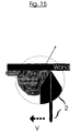
- FIG. 2 shows the use of the tool according to FIG. 1 on a wall.
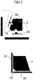
- FIG 3 shows a combination of the tool according to a preferred one Embodiment of the invention with the guide element according to one preferred embodiment of the invention in apart and assembled state.
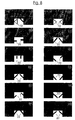
- Figs. 4, 5, 6, 7 and 8 show sectional views of different embodiments of holding sections in the tool according to a preferred one Embodiment of the invention.
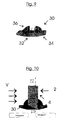
- Fig. 9 shows a perspective view of the guide element according to a preferred embodiment of the invention.
- FIG 10 shows a sectional view of a combination of the tool according to FIG a preferred embodiment of the invention and the guide element according to a preferred embodiment of the invention.
- FIG. 11 shows a further sectional view of the combination according to FIG. 10.
- FIG. 12 shows various engagement states of the combination according to FIG. 11.
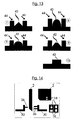
- FIG. 13 shows sectional views of the guide element according to a preferred one Embodiment of the invention.
- FIG. 14 shows another embodiment of a combination of the tool according to a preferred embodiment of the invention with the Guide element according to a preferred embodiment of the invention in disassembled state.
- the tool 1 shows a tool for processing, compacting, smoothing and / or Reworking plastic masses such as joint sealants or Grouts.
- the tool 2 is essentially plate-shaped and elastic formed and has at least one cutting edge 4 and two thereon adjacent cutting edges 6, 8.
- the adjacent cutting edges 6, 8 are essentially vertical or at an angle other than 90 ° on the cutting edge 4 and are each via a connecting region 10, 12 connected to the cutting edge 4.
- the connection areas 10, 12 can be designed to have an angle, i.e. are linear or have a groove-forming recess.
- Tool 2 can be designed so that the connection areas different Angles, lengths and / or various fillet shapes or curves of the Have recesses.
- the cutting edge 4 can also be a concave Include recess or a joint nose.
- the tool points in the area of the cutting edge 4, the neighboring one Cutting edges 6, 8 and the connecting areas 10, 12 preferably one only one-sided undercut 14, the Undercut is located on the back of tool 2.
- the undercut 14 is seen in the pull-off direction V. behind the cutting edge 4 or the adjacent cutting edges 6, 8 (see FIG. 2). This advantageously prevents the joint compound 16 to be removed from mushrooming, so that the removed grout 16 in the direction of removal W on the Tool 2 moves.
- a spreading of the grout on the Underground (e.g. the neighboring tiles) by a (at least partially) Lifting of the cutting edge 4 can advantageously be prevented.
- the tool 2 also has at least one fastening or Holding section 18 in the region of the cutting edge 4 and / or adjacent Cutting edge 6, 8 for holding or fastening a guide element 20 (see Fig. 3).
- the holding sections 18 are essentially designed as a recess, which can have a rectangular, oval, circular or similar shape.
- the resilient device 22 for Resilient arrangement of the guide element 20 is provided.
- the resilient device can be designed as an element be arranged in the holding section 18 of the tool 2.
- the Element can be a square, rectangular, triangular, trapezoidal and / or have diamond-shaped, round, conical and / or oval shape.
- the Resilient device 22 can be formed both in one part and in several parts.
- the elements or parts of the resilient device 22 may consist of individual ones flexible or inflexible forms exist, like one or more, universal or interrupted, full or semi-elliptical or round bands or Lamellae.
- a continuous or interrupted rounding or Ellipse can be provided that directly with their half or partial radius on the Holding section 18 of the tool 2 or a plunger or base 24 attached is.
- a band or a lamella that is interrupted is also conceivable Rounding or ellipse is formed, the ends of which are free-floating and the with its lower curved edge directly on the tool 2 or ram or Base 24 are attached.
- the tool 2 can also have a holding section 18 have, which in the form of at least one recess 26 on the base of the tool 2 is formed.
- the recess 26 can be different Have cross-sectional areas, e.g. round, elliptical, polygonal, etc.
- FIG. 9 shows a perspective view of the guide element 30 according to a preferred embodiment.
- the guide element 30 assigns one to it machined workpiece-facing side on a sliding surface 32, which at least on their perpendicular to the direction of movement or deduction direction V des Guide element 30 or tool 2 arranged edge areas Rounding or bevels 34 has.
- V des Guide element 30 or tool 2 arranged edge areas Rounding or bevels 34 has.
- To attach the Guide element 30 on a tool 2 has a guide element 30 Recording or holder 36 on the at least in the form of a recess partial reception of the tool 2 can be formed (see. Fig. 9) or at least one connecting element 38 for engaging in a recess 26 of the tool 2 (see FIG. 14).
- the arrangement of the guide element 30 for the tool 2 is shown in section in FIG. 10.
- Fig. 11 shows one Section along the line I-I of Fig. 10.
- the tool 2 has a resilient Device 22 on which the guide element 30 substantially opposed biased in a printing direction U
- Fig. 12 shows different ones - from the one exerted against the guide element 30 Pressure dependent - states of the combination of tool 2 with the Guide element 30.
- the guide element 30 can alone or also have a resilient device 40.
- alternative or in addition to the resilient device 40 may be on the Guide element 30 also be formed a plunger 42, which is designed is to be contacted with the resilient device 22 of the tool 2.
- Such plunger shapes are shown in Fig. 13.
- the plunger 42 can be one square, rectangular, triangular, trapezoidal and / or diamond-shaped, round, have conical and / or oval shape, which as a connection for the Guide element 30 with the tool 2, they can shaped differently and made of a flexible or inflexible material can be trained.
- the guide element 30 can at least have a guide portion 44 around the guide member 30 in the tool 2 to guide or guide in its movement and thus to tilt etc. avoid.
- the shapes can be used as inlays for the holding section in the Tool or the receptacles of the guide element are used, to engage the guide element at the level / height of the Cutting or leading edges or a distance bridging enable
- the receptacles or holding sections themselves or Inserts have shapes that are axially centered from the receiving base or Tappet or base, vertical or horizontal or inclined at any angle, tilted or flattened to provide a connection between Guide element and tool for bridging the distance produce or an indentation of the guide element at level / height to enable the cutting or leading edges
- the shapes can be directly in the tool or on the side Tool or guide element may be attached so that Guide element can be attached for the purpose of bridging the distance, which allows indentation through these shapes.
Landscapes
- Engineering & Computer Science (AREA)
- Architecture (AREA)
- Civil Engineering (AREA)
- Structural Engineering (AREA)
- Road Repair (AREA)
Abstract
Description
- ein oder mehrere, durchgängige oder unterbrochene, voll oder halb ellipsenförmige oder runde Bänder oder Lamellen (schmales bzw. breites Band) (vgl. Fig. 7, Nr. 37, 39, 42, 47)
- eine durchgängige oder unterbrochene Rundung oder Ellipse, die direkt mit ihren Halb- oder Teilradius an dem Halteabschnitt bzw. dem Stößel oder Sockel des Werkzeugs befestigt ist (vgl. Fig. 7, Nr. 37, 39, 42, 47)
- ein Band oder eine Lamelle, die als eine unterbrochene Rundung oder Ellipse ausgebildet sein kann, deren Enden frei schwebend sind und die mit ihrem unterem gebogenen Rand direkt an dem Halteabschnitt oder am Stößel oder einem Sockel des Werkzeugs befestigt sind (vgl. Fig. 7, Nr. 41 )
- zwei durchgängige oder unterbrochene, ellipsenförmige oder runde Bänder oder Lamellen, die mit ihren Rundungen gegeneinander zeigen und die direkt miteinander verbunden sind oder einen Abstand zueinander aufweisen, wobei diese Bänder oder Lamellen seitlich oder am Boden der Ausnehmung oder dem Halteabschnitt angebracht sind (vgl. Fig. 4, Nr.: 11 - 15)
- drei ellipsenförmige oder runde Bänder oder Lamellen, die mit ihren Rundungen oder Halbrundungen alle gegeneinander oder mit mindestens einer Rundung oder Halbrundung zueinander zeigen, die allesamt miteinander verbunden oder teilweise oder gänzlich unterbrochen sind (vgl. Fig. 5, Nr. 25, 26, 30; Fig. 6, Nr. 31 - 36)
- eine oder mehrere Lamellen oder Pins bzw. Stifte, die an den Seiten oder dem Boden der Ausnehmung des Führungselements oder des Halteabschnitts im Werkzeug oder am Stößel bzw. Sockel in gleicher oder unterschiedlicher Höhe, Form oder Winkel angebracht sind (vgl. Fig. 8, Nr. 49 - 60)
- eine oder mehrere Lamellen oder ein oder mehrere Pins bzw. Stifte mit gleicher oder unterschiedlicher Materialdicke, Materialbreite, Materiallänge oder Materialart, die am Boden, Stößel bzw. Sockel oder an den Seiten der Ausnehmung des Führungselements oder des Halteabschnitts des Werkzeugs in gleicher und unterschiedlicher Höhe einzeln oder miteinander in unterschiedlichen oder gleichen Formen verbunden oder unterbrochen angebracht sind, wobei die Anordnung der Lamellen oder Pins/Stifte auf gleicher oder ungleicher Ebene und/oder in unterschiedlichen Winkeln zueinander zur Aufnahmeöffnung oder zum Aufnahmeboden erfolgen und wobei die Lamellen/Pins/Stiftenden rund oder zusätzlich den Federungseffekt verstärkend halbseitig abgeschrägt (vgl. Fig. 5, Nr. 22, 23, 24) mit der Abschrägung zum oder vom Führungselement zeigen oder auf dem Aufnahmeboden sowie solitär senkrecht in der Aufnahme bzw. Dem Halteabschnitt stehen (vgl. Fig. 8, Nr. 49 - 60)
- 2
- Werkzeug
- 4
- Schneidkante
- 6, 8
- benachbarte Schneidkante
- 10, 12
- Verbindungsbereich
- 14
- Hinterschneidung
- 16
- Fugenmasse
- 18
- Halteabschnitt
- 20
- Führungselement
- 22
- rückstellfähige Einrichtung
- 24
- Sockel
- 26
- Ausnehmung
- 30
- Führungselement
- 32
- Gleitfläche
- 34
- Abschrägung
- 36
- Aufnahme bzw. Halterung
- 38
- Verbindungselement
- 40
- rückstellfähige Einrichtung
- 42
- Stößel
- 44
- Leitabschnitt
- U
- Druckrichtung
- V
- Abzugsrichtung
- W
- Abtragsrichtung
Claims (19)
- Werkzeug zum Verarbeiten, Verdichten, Glätten und/oder Nachbearbeiten von plastischen Massen, insbesondere Fugenmassen bei Verfugungs- bzw. Abdichtungsarbeiten, welches aus einem elastischen, an seinen Oberflächen glatten Material gebildet ist und wenigstens eine Schneidkante (4) und zwei daran benachbarte Schneidkanten (6, 8) aufweist, wobei wenigstens ein Halteabschnitt (18) für ein gesondertes Führungselement (30) am Werkzeug (2) vorgesehen ist.
- Werkzeug nach Anspruch 1, wobei die benachbarten Schneidkanten (6, 8) jeweils über einen Verbindungsbereich (10, 12) mit der Schneidkante (4) verbunden sind und wobei das Werkzeug (2) im Bereich der Schneidkante (4), der benachbarten Schneidkanten (6, 8) und/oder der Verbindungsbereiche (10, 12) eine lediglich einseitige Hinterschneidung (14) aufweist.
- Werkzeug nach Anspruch 2, wobei die Hinterschneidung (14) einen Winkel zwischen etwa 30° und etwa 80°, bevorzugterweise etwa 45°, zu einer Grundfläche des Werkzeugs (2) aufweist.
- Werkzeug nach einem der vorhergehenden Ansprüche, wobei der Halteabschnitt (18) in Form eines Rücksprungs an der Schneidkante (4) und/oder der benachbarten Schneidkante(n) (6, 8) ausgebildet ist.
- Werkzeug nach einem der vorhergehenden Ansprüche, wobei der Halteabschnitt (18) in Form wenigstens einer Ausnehmung (26) an der Grundfläche des Werkzeugs (2) ausgebildet ist.
- Werkzeug nach einem der vorhergehenden Ansprüche, wobei der Halteabschnitt (18) eine rückstellfähige Einrichtung (22) zum rückstellfähigen Anordnen des Führungselements (30) aufweist.
- Werkzeug nach Anspruch 6, wobei die rückstellfähige Einrichtung (22) ausgebildet ist, das Führungselement (30) in einer Richtung im wesentlichen parallel zu der Grundfläche des Werkzeugs (2) weg von dem Werkzeug (2) vorzuspannen.
- Werkzeug nach einem der vorhergehenden Ansprüche, wobei die benachbarten Schneidkanten (6, 8) senkrecht und/oder in einem von 90° verschiedenen Winkel zu der Schneidkante (4) angeordnet sind.
- Werkzeug nach einem der vorhergehenden Ansprüche, wobei die Verbindungsbereiche (10, 12) zwischen den benachbarten Schneidkanten (6, 8) und der Schneidkante (4) unterschiedlich ausgeformt sind.
- Werkzeug nach einem der vorhergehenden Ansprüche, wobei das Werkzeug (2) aus einem die plastische Masse abweisenden Material ausgebildet ist.
- Führungselement zum Führen eines Werkzeugs zum Verarbeiten, Verdichten, Glätten und/oder Nachbearbeiten von plastischen Massen, insbesondere eines Werkzeugs nach einem der vorhergehenden Ansprüche, umfassend
eine Führungs- bzw. Gleitfläche (32) zum Führen des Werkzeugs (2) entlang einer Ebene und eine Aufnahme (36) zum zumindest teilweise Aufnehmen des Werkzeugs (2). - Führungselement nach Anspruch 11, wobei die Gleitfläche (32) wenigstens an ihren senkrecht zur Bewegungsrichtung des Führungselements (30) angeordneten Randbereichen abgerundet und/oder abgeschrägt ist.
- Führungselement nach einem der Ansprüche 11 oder 12, wobei die Aufnahme (36) im wesentlichen als Rücksprung zum Aufnehmen des Werkzeugs (2) ausgebildet ist oder wenigstens ein Verbindungselement (38), insbesondere in Form von Steckelementen oder Pins, zum Eingreifen in einen Halteabschnitt (18) des Werkzeugs (2) aufweist.
- Führungselement nach einem der Ansprüche 11 - 13, wobei die Aufnahme (36) eine rückstellfähige Einrichtung (40) zum rückstellfähigen Anordnen des Führungselements (30) an einem Werkzeug (2) aufweist.
- Führungselement nach einem der Ansprüche 11 - 14, wobei die Aufnahme (36) einen Kontaktabschnitt (42), insbesondere einen Stößel, zum Kontaktieren mit einer rückstellfähigen Einrichtung (22) eines Werkzeugs (2) aufweist.
- Führungselement nach einem der Ansprüche 11 - 15, weiterhin aufweisend einen Leitabschnitt (44) zum Leiten des Führungselements (30) in dem Werkzeug (2) im wesentlichen in einer parallel zu einer Grundfläche des Werkzeugs (2) liegenden Richtung.
- Führungselement nach einem der Ansprüche 11 - 16, wobei die Aufnahme (36) entsprechend zu einer Hinterschneidung (14) des Werkzeugs ausgebildet ist.
- Kombination aus einem Werkzeug (2) nach einem der Ansprüche 1 - 10 und einem Führungselement (30) nach einem der Ansprüche 11 - 16.
- Verwendung einer Kombination aus einem Werkzeug (2) nach einem der Ansprüche 1 - 10 und einem Führungselement (30) nach einem der Ansprüche 11 - 16 zum Verarbeiten, Verdichten, Glätten und/oder Nachbearbeiten von plastischen Massen.
Applications Claiming Priority (4)
| Application Number | Priority Date | Filing Date | Title |
|---|---|---|---|
| DE20309043U | 2003-06-09 | ||
| DE20309043U DE20309043U1 (de) | 2003-06-09 | 2003-06-09 | Aufnahme für Werkzeuge + Adapter sowie für Adapter + Werkzeuge für Verarbeitung von plastischen Massen |
| DE10351388A DE10351388B4 (de) | 2003-06-09 | 2003-11-04 | Flexibles Dichtmassen abweisendes Werkzeug |
| DE10351388 | 2003-11-04 |
Publications (1)
| Publication Number | Publication Date |
|---|---|
| EP1489247A1 true EP1489247A1 (de) | 2004-12-22 |
Family
ID=33420032
Family Applications (1)
| Application Number | Title | Priority Date | Filing Date |
|---|---|---|---|
| EP04013623A Withdrawn EP1489247A1 (de) | 2003-06-09 | 2004-06-09 | Flexibles Dichtmassen abweisendes Werkzeug |
Country Status (1)
| Country | Link |
|---|---|
| EP (1) | EP1489247A1 (de) |
Cited By (1)
| Publication number | Priority date | Publication date | Assignee | Title |
|---|---|---|---|---|
| EP3283235B1 (de) * | 2015-04-14 | 2023-05-31 | Henkel AG & Co. KGaA | Applikator zum auftragen einer dichtmasse |
Citations (6)
| Publication number | Priority date | Publication date | Assignee | Title |
|---|---|---|---|---|
| US3936210A (en) * | 1974-11-13 | 1976-02-03 | Oehlerking Erwin L | Concrete float and accessory therefor |
| DE2904236A1 (de) * | 1979-02-05 | 1980-08-07 | Secuplan Belagtechnik Gmbh | Verfahren zur herstellung von standfesten und gradlinig verlaufenden fugenkanten fuer industriefussboden |
| US5057002A (en) * | 1990-04-06 | 1991-10-15 | Whited Preston D | Bead shaper |
| US5075916A (en) | 1990-11-27 | 1991-12-31 | Englehart Ross L | Tool for forming smooth caulked joints |
| GB2245919A (en) * | 1990-07-13 | 1992-01-15 | Stonemarket | A pointing device |
| DE19847514A1 (de) * | 1998-01-26 | 2000-05-11 | Lutz Keidel | 2 Werkzeuge zur Verarbeitung, Verdichten, Glätten und Nachbearbeitung von allen plastischen Fugenmassen |
-
2004
- 2004-06-09 EP EP04013623A patent/EP1489247A1/de not_active Withdrawn
Patent Citations (6)
| Publication number | Priority date | Publication date | Assignee | Title |
|---|---|---|---|---|
| US3936210A (en) * | 1974-11-13 | 1976-02-03 | Oehlerking Erwin L | Concrete float and accessory therefor |
| DE2904236A1 (de) * | 1979-02-05 | 1980-08-07 | Secuplan Belagtechnik Gmbh | Verfahren zur herstellung von standfesten und gradlinig verlaufenden fugenkanten fuer industriefussboden |
| US5057002A (en) * | 1990-04-06 | 1991-10-15 | Whited Preston D | Bead shaper |
| GB2245919A (en) * | 1990-07-13 | 1992-01-15 | Stonemarket | A pointing device |
| US5075916A (en) | 1990-11-27 | 1991-12-31 | Englehart Ross L | Tool for forming smooth caulked joints |
| DE19847514A1 (de) * | 1998-01-26 | 2000-05-11 | Lutz Keidel | 2 Werkzeuge zur Verarbeitung, Verdichten, Glätten und Nachbearbeitung von allen plastischen Fugenmassen |
Cited By (1)
| Publication number | Priority date | Publication date | Assignee | Title |
|---|---|---|---|---|
| EP3283235B1 (de) * | 2015-04-14 | 2023-05-31 | Henkel AG & Co. KGaA | Applikator zum auftragen einer dichtmasse |
Similar Documents
| Publication | Publication Date | Title |
|---|---|---|
| WO2001051733A1 (de) | Paneelelement | |
| DE2426322A1 (de) | Spachtel | |
| EP2942109B1 (de) | Vorrichtung zur herstellung von fugen zwischen im winkel aufeinander stossenden bauteilen | |
| DE9413523U1 (de) | Werkzeug zur Nacharbeit von Fugen aus dauerelastischer Fugenmasse | |
| DE2154039A1 (de) | Verbundstein | |
| DE10021993B4 (de) | Rinnenschuss für Kettenkratzförderer | |
| DE10351388B4 (de) | Flexibles Dichtmassen abweisendes Werkzeug | |
| EP3033465A1 (de) | Verfahren zum ausfüllen einer fuge mit einem kleb- und/oder dichtstoff sowie system zum ausfüllen einer fuge mit einem kleb- und/oder dichtstoff | |
| DE8303526U1 (de) | Spiralbohrer | |
| EP0681083B1 (de) | Geradverbinder aus Kunststoff zur Verbindung von hohlen Abstandsprofilen und hohlen Sprossenprofilen eines Mehrscheibenisolierglases | |
| EP1666683B1 (de) | Werkzeug zum Nachbearbeiten und Glätten plastischer Fugenmasse | |
| DE102010045992A1 (de) | Verfugungswerkzeug | |
| EP3434844B1 (de) | Mörtelschlitten | |
| DE910589C (de) | Anordnung zur Befestigung von Schutzgittern u. dgl. | |
| DE102007062106B4 (de) | Verbindung für Fußbodenpaneele | |
| DE102018122840A1 (de) | Vorrichtung zum Verarbeiten von Kleb- und Dichtstoffen | |
| DE20004426U1 (de) | Fugenschaber | |
| DE9108560U1 (de) | Werkzeug zum Einbringen von Hinterfüllungsmaterial in eine Fuge | |
| EP4375452A1 (de) | Werkzeug zum nacharbeiten und glätten von fugen | |
| DE20112765U1 (de) | Fugenglätter | |
| DE10301590B3 (de) | Dichtungsmesser | |
| EP1353024A2 (de) | Werkzeug zum Verformen plastischer Massen, insbesondere zum Erstellen von erhabenen Profilen | |
| DE7614272U1 (de) | Mauerstein | |
| DE3218401A1 (de) | Glasbaustein, wandteil aus glasbausteinen, und verfahren zum verlegen und einbauen solcher glasbausteine | |
| EP4365388A1 (de) | Glättwerkzeug zur nachbearbeitung von einer mit einer fugenmasse gefüllten fuge |
Legal Events
| Date | Code | Title | Description |
|---|---|---|---|
| PUAI | Public reference made under article 153(3) epc to a published international application that has entered the european phase |
Free format text: ORIGINAL CODE: 0009012 |
|
| AK | Designated contracting states |
Kind code of ref document: A1 Designated state(s): AT BE BG CH CY CZ DE DK EE ES FI FR GB GR HU IE IT LI LU MC NL PL PT RO SE SI SK TR |
|
| AX | Request for extension of the european patent |
Extension state: AL HR LT LV MK |
|
| 17P | Request for examination filed |
Effective date: 20050620 |
|
| AKX | Designation fees paid |
Designated state(s): AT BE BG CH CY CZ DE DK EE ES FI FR GB GR HU IE IT LI LU MC NL PL PT RO SE SI SK TR |
|
| 17Q | First examination report despatched |
Effective date: 20070820 |
|
| GRAP | Despatch of communication of intention to grant a patent |
Free format text: ORIGINAL CODE: EPIDOSNIGR1 |
|
| STAA | Information on the status of an ep patent application or granted ep patent |
Free format text: STATUS: THE APPLICATION IS DEEMED TO BE WITHDRAWN |
|
| 18D | Application deemed to be withdrawn |
Effective date: 20130730 |