EP1489314A2 - Articulation à rotule - Google Patents
Articulation à rotule Download PDFInfo
- Publication number
- EP1489314A2 EP1489314A2 EP04014166A EP04014166A EP1489314A2 EP 1489314 A2 EP1489314 A2 EP 1489314A2 EP 04014166 A EP04014166 A EP 04014166A EP 04014166 A EP04014166 A EP 04014166A EP 1489314 A2 EP1489314 A2 EP 1489314A2
- Authority
- EP
- European Patent Office
- Prior art keywords
- bearing shell
- ball
- joint
- housing
- joint housing
- Prior art date
- Legal status (The legal status is an assumption and is not a legal conclusion. Google has not performed a legal analysis and makes no representation as to the accuracy of the status listed.)
- Withdrawn
Links
- 238000004873 anchoring Methods 0.000 claims abstract description 9
- 238000005461 lubrication Methods 0.000 claims description 9
- 238000004519 manufacturing process Methods 0.000 abstract description 11
- 238000003825 pressing Methods 0.000 description 10
- 239000000314 lubricant Substances 0.000 description 5
- 238000000034 method Methods 0.000 description 5
- 238000009826 distribution Methods 0.000 description 2
- 238000003780 insertion Methods 0.000 description 2
- 230000037431 insertion Effects 0.000 description 2
- 239000000463 material Substances 0.000 description 2
- 230000036316 preload Effects 0.000 description 2
- 239000003082 abrasive agent Substances 0.000 description 1
- 238000010521 absorption reaction Methods 0.000 description 1
- 238000004026 adhesive bonding Methods 0.000 description 1
- 238000006243 chemical reaction Methods 0.000 description 1
- 230000000295 complement effect Effects 0.000 description 1
- 230000001419 dependent effect Effects 0.000 description 1
- 230000000694 effects Effects 0.000 description 1
- 230000001105 regulatory effect Effects 0.000 description 1
- 238000007789 sealing Methods 0.000 description 1
- 230000035939 shock Effects 0.000 description 1
- 238000003860 storage Methods 0.000 description 1
- 238000009827 uniform distribution Methods 0.000 description 1
- 238000011179 visual inspection Methods 0.000 description 1
Images

Classifications
-
- F—MECHANICAL ENGINEERING; LIGHTING; HEATING; WEAPONS; BLASTING
- F16—ENGINEERING ELEMENTS AND UNITS; GENERAL MEASURES FOR PRODUCING AND MAINTAINING EFFECTIVE FUNCTIONING OF MACHINES OR INSTALLATIONS; THERMAL INSULATION IN GENERAL
- F16C—SHAFTS; FLEXIBLE SHAFTS; ELEMENTS OR CRANKSHAFT MECHANISMS; ROTARY BODIES OTHER THAN GEARING ELEMENTS; BEARINGS
- F16C11/00—Pivots; Pivotal connections
- F16C11/04—Pivotal connections
- F16C11/06—Ball-joints; Other joints having more than one degree of angular freedom, i.e. universal joints
- F16C11/0619—Ball-joints; Other joints having more than one degree of angular freedom, i.e. universal joints the female part comprising a blind socket receiving the male part
- F16C11/0623—Construction or details of the socket member
- F16C11/0628—Construction or details of the socket member with linings
- F16C11/0633—Construction or details of the socket member with linings the linings being made of plastics
-
- Y—GENERAL TAGGING OF NEW TECHNOLOGICAL DEVELOPMENTS; GENERAL TAGGING OF CROSS-SECTIONAL TECHNOLOGIES SPANNING OVER SEVERAL SECTIONS OF THE IPC; TECHNICAL SUBJECTS COVERED BY FORMER USPC CROSS-REFERENCE ART COLLECTIONS [XRACs] AND DIGESTS
- Y10—TECHNICAL SUBJECTS COVERED BY FORMER USPC
- Y10T—TECHNICAL SUBJECTS COVERED BY FORMER US CLASSIFICATION
- Y10T403/00—Joints and connections
- Y10T403/32—Articulated members
- Y10T403/32606—Pivoted
- Y10T403/32631—Universal ball and socket
-
- Y—GENERAL TAGGING OF NEW TECHNOLOGICAL DEVELOPMENTS; GENERAL TAGGING OF CROSS-SECTIONAL TECHNOLOGIES SPANNING OVER SEVERAL SECTIONS OF THE IPC; TECHNICAL SUBJECTS COVERED BY FORMER USPC CROSS-REFERENCE ART COLLECTIONS [XRACs] AND DIGESTS
- Y10—TECHNICAL SUBJECTS COVERED BY FORMER USPC
- Y10T—TECHNICAL SUBJECTS COVERED BY FORMER US CLASSIFICATION
- Y10T403/00—Joints and connections
- Y10T403/32—Articulated members
- Y10T403/32606—Pivoted
- Y10T403/32631—Universal ball and socket
- Y10T403/32681—Composite ball
- Y10T403/32704—Stud extends into ball
-
- Y—GENERAL TAGGING OF NEW TECHNOLOGICAL DEVELOPMENTS; GENERAL TAGGING OF CROSS-SECTIONAL TECHNOLOGIES SPANNING OVER SEVERAL SECTIONS OF THE IPC; TECHNICAL SUBJECTS COVERED BY FORMER USPC CROSS-REFERENCE ART COLLECTIONS [XRACs] AND DIGESTS
- Y10—TECHNICAL SUBJECTS COVERED BY FORMER USPC
- Y10T—TECHNICAL SUBJECTS COVERED BY FORMER US CLASSIFICATION
- Y10T403/00—Joints and connections
- Y10T403/32—Articulated members
- Y10T403/32606—Pivoted
- Y10T403/32631—Universal ball and socket
- Y10T403/32721—Elastomeric seat
-
- Y—GENERAL TAGGING OF NEW TECHNOLOGICAL DEVELOPMENTS; GENERAL TAGGING OF CROSS-SECTIONAL TECHNOLOGIES SPANNING OVER SEVERAL SECTIONS OF THE IPC; TECHNICAL SUBJECTS COVERED BY FORMER USPC CROSS-REFERENCE ART COLLECTIONS [XRACs] AND DIGESTS
- Y10—TECHNICAL SUBJECTS COVERED BY FORMER USPC
- Y10T—TECHNICAL SUBJECTS COVERED BY FORMER US CLASSIFICATION
- Y10T403/00—Joints and connections
- Y10T403/32—Articulated members
- Y10T403/32606—Pivoted
- Y10T403/32631—Universal ball and socket
- Y10T403/32737—Universal ball and socket including liner, shim, or discrete seat
Definitions
- the invention relates to a ball joint, in particular for a pendulum support of a motor vehicle, according to the preamble of patent claim 1.
- Ball joints of the type mentioned at the outset are used, for example, but by no means exclusively, in pendulum supports with which force or torque-related reaction movements, for example of drives, units or chassis parts on the motor vehicle, are to be damped or prevented.
- Such a ball joint is known for example from US 6,190,080 B1.
- This ball joint has a hollow cylindrical joint housing, in the Interior of a plastic bearing shell for slidably accommodating the a ball pin arranged joint ball is used.
- the bearing shell of the in the disclosed ball joint is based in the axial direction the joint housing by means of two circumferential ring collars on the two end faces of the joint housing.
- the first of the two circumferential ring bundles is the one from the start Plastic bearing shell molded during the first ring collar opposite second collar of the bearing shell in the known Ball joint is in the form of an annular snap connection, which by Pressing an additional lid is stabilized.
- the ball joint according to the present invention is known in the art Have a substantially ring-shaped or pot-shaped joint housing, in the Interior of a bearing shell can be arranged, which in turn is the joint ball Ball pin slidably receives.
- the inner contour of the joint housing and the outer contour of the bearing shell is essentially frustoconical educated.
- the ball joint is characterized in that the Bearing shell in the joint housing essentially free in the journal axial direction is positionable.
- the bearing shell is not as in the prior art up to one based on the geometry of the bearing shell and Articulated housing fixed stop inserted or pressed.
- Ball joint according to the invention is such an axial stop for fixing the Rather, the journal-axial position of the bearing shell in the joint housing is not at all present, but the bearing shell is in a certain area around your Nominal position can be moved in the axial direction in the joint housing.
- the anchoring of the bearing shell in the joint housing leads over the controllable, pressed conical surfaces into one overall much better, more robust and more permanent connection between Bearing shell and joint housing, as this is possible with the known anchorages is, in which essentially with axial stops or axial Anchoring forces is being worked on.
- the bearing shell is anchored in the joint housing that for the Pitch angle of the frustoconical outer contour of the bearing shell and the likewise a frustoconical inner contour of the joint housing is such a small value is used that the friction angle of the material pairing of the bearing shell and Joint housing is undershot; in other words, that self-locking between the bearing shell and the joint housing. That way it will in principle possible, the bearing shell only by axially pressing into the Joint housing controlled and permanently connected to the joint housing.
- the bearing shell is axially fixed relative to the joint housing by a clamping ring arranged between the joint housing and the bearing shell.
- This axial fixation can be provided in addition to a self-locking geometry of the bearing shell and joint housing as a further security against pulling the bearing shell out of the joint housing.
- the axial fixation by means of a clamping ring can, however, also be used if the pitch angle for the outer contour of the bearing shell and joint housing is selected so that sufficient self-locking is not guaranteed.
- the clamping ring can be arranged on the ball pin side on the joint housing.
- the clamping ring exerts an additional compressive force on the bearing shell, which presses the bearing shell into the conical joint housing, or prevents loosening of the connection between the bearing shell and the joint housing.
- the clamping ring can also be arranged on the housing cover side or on the side facing away from the ball pin on the joint housing.
- the bearing shell is fixed in the joint housing by the clamping ring by means of additional tensile forces exerted on the bearing shell.
- a clamping ring arranged opposite the ball stud has a number of additional advantages. First of all, the structure of the entire ball joint, in particular, however, of the joint housing, is further considerably simplified.
- the assembly of the ball joint is particularly easy and therefore inexpensive due to the easier accessibility of the clamping ring opposite the ball pin.
- a ball joint with such a clamping ring arrangement can be readjusted again in a particularly simple manner and without complex special devices by simple re-pressing in the event of wear during operation.
- the clamping ring opposite the ball pin also allows a better visual inspection of the safe assembly state of the ball joint.
- the bearing shell has Area of the equator of the joint ball on the ball side and / or on the housing side preferably circumferential surface recess. This equatorial recess relieves the area of the bearing shell close to the atom, which is usually the smallest Has wall thickness, from the radial forces generated during the pressing. On this way, uneven force distributions between the ball and Bearing shell and associated clamping of the ball in the bearing shell or Avoid uneven wear of ball and bearing shell.
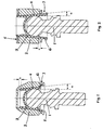
- FIG. 1 a first embodiment of a ball joint according to the invention is shown in longitudinal section.
- the ball stud 1, the joint housing 2 and the bearing shell 3, which are mostly made of plastic, can first be seen.
- the ball joint shown in FIG. 1 has a joint housing 2 with a frustoconical inner contour 4.
- the bearing shell 3, which also has a frustoconical outer contour is pressed into the joint housing 2 together with the ball pin 1.
- the cone angle ⁇ is chosen so small that with regard to the material pairing present between the joint housing 2 and the bearing shell 3, there is self-locking, which means that the bearing shell 3 does not automatically - due to the essentially radial pressing force between the joint housing 2 and the bearing shell 3 - in the axial direction Direction can slide out of the joint housing 2.
- a clamping ring 5 arranged between the joint housing 2 and the bearing shell 3 is provided for additional securing and fixing of the bearing shell 3 in the joint housing 2.
- the clamping ring 5 can be steplessly positioned on the inside of the cylindrical region 6 of the joint housing 2 in order to fix the bearing shell 3 in the respective position determined during the pressing in.
- the cylindrical region 6 of the joint housing 2 simultaneously forms on its outer diameter a bellows groove 7 for the sealing bellows of the ball joint, not shown in the figure.
- connection between the bearing shell 3 and the joint housing 2 now primarily the total exposed to a very high radial pressing force Outer contour 4 of the bearing shell 3 or the entire length of the inner contour 4 of the Joint housing 2 involved, and not only as in the prior art Shoulders of two axial stops of the bearing shell, which are mostly small Apply contact pressure to the respective face of the joint housing.
- Ball joint in addition to significantly improved reliability and resilience in Operation can also be produced extremely inexpensively because of the assembly of the ball joint essentially consists of a single press-in process.
- the Ball joint according to the invention can also during manufacture, or also a later point in its life, by varying the Press-in depth of the bearing shell 3 in the joint housing 2 with respect to the bearing play between ball stud and bearing shell 3, in relation to the total elasticity of the Ball joint and in relation to the breakaway and friction moments of the Ball stud 1 can be regulated or adjusted.
- Figure 2 shows another in a longitudinal sectional view corresponding to Figure 1 Embodiment of a ball joint according to the invention.
- the ball joint according to Figure 2 differs essentially by the open, annular shape of the Articulated housing 2 and by the arrangement of the clamping ring 5.
- the securing the position of the pressed-in bearing shell 3 in the joint housing 2 serving Clamping ring 5 is in the ball joint according to Figure 2 on the drawing Upper end of the joint housing 2 arranged, the Ball pin 1 is opposite.
- An advantage of this arrangement of the clamping ring 5 is in particular that the Clamping ring 5 due to the easier assembly of the ball joint accessible side facing away from the joint housing 2 even easier and can be positioned and assembled more quickly. Furthermore, the structure of the Ball joint, in particular the shape of the joint housing, considerably further simplified, as a comparison of Figures 1 and 2 shows.
- FIG. 2 It can be seen in FIG. 2 that one is arranged opposite the ball pin 1 Clamping ring 5 essentially only the joint housing 2 of the ball joint is formed by the annular body 2.
- the bellows groove 7 can also be used this arrangement of the clamping ring 5 in the simplest way on the Arrange the plastic bearing shell 3.
- the larger diameter and the larger width of the clamping ring 5 higher elasticities and thus higher Clamping forces in the clamping ring 5, which the bearing shell 3 and the joint housing 2 thus hold together particularly securely.
- Figure 3 shows the area of the joint housing 2 and the bearing shell 3 one Embodiment of the ball joint according to the invention in an enlarged schematic sectional view. It is a variant of the Ball joint, in which the clamping ring 5 on the side facing away from the pin Joint housing 2 is arranged.
- the axial adjustability e according to the invention of the bearing shell 3 in the joint housing 2- in particular two equatorial recesses 8 and 9, one of which Equatorial recess 8 circumferentially on the spherical surface of the Bearing shell 3 and the other equatorial recess 9 also annular arranged all around on the joint housing surface 4 of the bearing shell 3 is.
- the equatorial recesses 8, 9 serve to close the area of the equator Relieve the bearing shell 3 from the radial compressive stresses that occur during the pressing the bearing shell 3 in the joint housing 2 arise. Otherwise, these could be Clamp the joint ball in the bearing shell 3, or too uneven Wear of joint ball and bearing shell 3 during the operation of the Ball joint lead, especially since the bearing shell 3 in the area close to the equator the joint ball has the area of its smallest wall thickness.
- Lubrication grooves 10 which ensure a uniform distribution of the lubricant between Bearing cup 3 and ball joint.
- the lubrication grooves 10 are at their Drawing-related downward-facing end in open connection with the Interior 11 of the bearing shell 3 in the region of the ball neck, not shown here.
- a lubricant supply can be deposited there when the ball joint is assembled from which the sliding area between the bearing shell 3 and the joint ball by means of the lubrication grooves 10 can always be supplied with lubricant. It also says also the inside equatorial recess 8, which the greases 10 with each other connects, available for the distribution of the lubricant.
Landscapes
- Engineering & Computer Science (AREA)
- General Engineering & Computer Science (AREA)
- Mechanical Engineering (AREA)
- Pivots And Pivotal Connections (AREA)
Applications Claiming Priority (2)
| Application Number | Priority Date | Filing Date | Title |
|---|---|---|---|
| DE10328109 | 2003-06-20 | ||
| DE10328109A DE10328109B4 (de) | 2003-06-20 | 2003-06-20 | Kugelgelenk |
Publications (2)
| Publication Number | Publication Date |
|---|---|
| EP1489314A2 true EP1489314A2 (fr) | 2004-12-22 |
| EP1489314A3 EP1489314A3 (fr) | 2005-06-15 |
Family
ID=33394938
Family Applications (1)
| Application Number | Title | Priority Date | Filing Date |
|---|---|---|---|
| EP04014166A Withdrawn EP1489314A3 (fr) | 2003-06-20 | 2004-06-17 | Articulation à rotule |
Country Status (3)
| Country | Link |
|---|---|
| US (1) | US7357590B2 (fr) |
| EP (1) | EP1489314A3 (fr) |
| DE (1) | DE10328109B4 (fr) |
Cited By (2)
| Publication number | Priority date | Publication date | Assignee | Title |
|---|---|---|---|---|
| US20180252258A1 (en) * | 2015-02-17 | 2018-09-06 | Nhk Spring Co., Ltd. | Stabilizer link |
| CN108896257A (zh) * | 2018-08-09 | 2018-11-27 | 华南理工大学 | 一种多功能不带连接部球铰试验工装 |
Families Citing this family (14)
| Publication number | Priority date | Publication date | Assignee | Title |
|---|---|---|---|---|
| ES2300730T3 (es) * | 2004-11-25 | 2008-06-16 | Industria Auxiliar Alavesa, S.A. (Inauxa, S.A.) | Dispositivo de junta de rotula. |
| EP1733861A3 (fr) * | 2005-06-14 | 2007-11-28 | Industria Auxiliar Alavesa, S.A. (Inauxa) | Articulation à rotule, procédé de fabrication et outillage |
| DE102006052254B4 (de) * | 2006-11-03 | 2012-12-20 | Zf Friedrichshafen Ag | Kugelgelenk |
| US9476447B2 (en) * | 2008-05-21 | 2016-10-25 | Federal-Mogul Powertrain, Inc. | Ball joint assembly and method of making |
| ES2354898B1 (es) * | 2009-06-30 | 2012-01-25 | Airbus Operations, S.L. | Soporte de rótulas en piezas de pequeño espesor. |
| KR101811451B1 (ko) * | 2011-06-29 | 2017-12-21 | 엘지이노텍 주식회사 | 볼 조인트 유닛 |
| US9546679B2 (en) * | 2012-03-14 | 2017-01-17 | Kabushiki Kaisha Somic Ishikawa | Bearing seat for a ball joint and a ball joint |
| JP6253337B2 (ja) * | 2013-10-17 | 2017-12-27 | 株式会社ソミック石川 | ボールシートおよびボールジョイント |
| DE102014109419B4 (de) * | 2014-07-04 | 2016-12-29 | Jun-Fan Chen | Lösewerkzeug für Kugelköpfe und entsprechende Baugruppen |
| US10960745B2 (en) * | 2016-03-10 | 2021-03-30 | Truck Accessories Group, Llc | Tonneau cover with prop rod assembly |
| DE102016207175A1 (de) * | 2016-04-27 | 2017-11-02 | Schaeffler Technologies AG & Co. KG | Schwenklager eines hydraulischen Spielausgleichselements |
| EP3669092B1 (fr) | 2017-08-16 | 2022-06-22 | Multimatic, Inc. | Joint à rotule avec palier moulé par injection |
| US11215221B1 (en) * | 2020-08-27 | 2022-01-04 | Musashi Auto Parts Canada Inc. | Ball joint assembly and method of assembly and ball joint compression ring |
| CN112077873B (zh) * | 2020-10-16 | 2024-07-30 | 深圳市萨博机器人工具技术有限公司 | 一种机臂连接结构及工业机器人 |
Family Cites Families (23)
| Publication number | Priority date | Publication date | Assignee | Title |
|---|---|---|---|---|
| US1918394A (en) * | 1927-12-24 | 1933-07-18 | Thompson Prod Inc | Tie rod ball joint |
| GB328877A (en) * | 1929-04-15 | 1930-05-08 | George Hiram Hufferd | Improvements in a ball joint |
| US2321157A (en) * | 1942-03-13 | 1943-06-08 | Illinois Tool Works | Fastener device |
| US2361025A (en) * | 1943-12-02 | 1944-10-24 | Thompson Prod Inc | Ball joint |
| US3413023A (en) * | 1965-04-26 | 1968-11-26 | Trw Inc | Preload-capsule joint |
| US3063744A (en) * | 1959-08-07 | 1962-11-13 | Columbus Auto Parts | Joint with bearing member |
| US3068031A (en) * | 1959-08-10 | 1962-12-11 | Thompson Ramo Wooldridge Inc | Ball joint assembly |
| JPS5382957A (en) * | 1976-12-29 | 1978-07-21 | Tokai Trw & Co | Method of fastening ball joint |
| JPS6263414U (fr) * | 1985-10-11 | 1987-04-20 | ||
| US4966488A (en) * | 1987-09-18 | 1990-10-30 | Weasler Engineering, Inc. | Ball retainer |
| DE4109697C1 (fr) * | 1991-03-23 | 1992-06-25 | Trw Ehrenreich Gmbh & Co Kg, 4000 Duesseldorf, De | |
| US5380114A (en) * | 1993-01-25 | 1995-01-10 | Trw Inc. | Ball joint assembly and method of mounting |
| DE4445251A1 (de) * | 1994-12-19 | 1996-01-11 | Daimler Benz Ag | Befestigungsanordnung zwischen einem Innenteil und einem Außenteil |
| US5704727A (en) * | 1995-10-31 | 1998-01-06 | Dana Corporation | Ball and socket joint assembly with self-centering retainer ring |
| DE19543688C2 (de) * | 1995-11-23 | 1998-04-09 | Trw Fahrwerksyst Gmbh & Co | Vorrichtung zur Festlegung einer Lagerschale eines Gelenkes in einer Aufnahmeöffnung |
| GB2309739B (en) * | 1996-01-31 | 2000-01-19 | Ivor Maldwyn Hugh Pagden | Ball joint mount |
| US5904436A (en) * | 1997-07-02 | 1999-05-18 | Dana Corporation | Dry wedge ball and socket joint |
| US5855448A (en) * | 1997-10-20 | 1999-01-05 | Ford Global Technologies, Inc. | Ball joint assembly |
| US6164861A (en) * | 1998-03-13 | 2000-12-26 | Dana Corporation | Bearing set for a ball joint assembly |
| US6042293A (en) * | 1998-03-31 | 2000-03-28 | Dana Corporation | Low torque ball and socket joint assembly |
| KR100272084B1 (ko) * | 1998-04-16 | 2000-11-15 | 강태릉 | 자동차용볼조인트 |
| DE19823781C5 (de) * | 1998-05-28 | 2006-10-05 | Trw Fahrwerksysteme Gmbh & Co Kg | Lagerschale |
| US6505990B1 (en) * | 2001-06-22 | 2003-01-14 | Dana Corporation | Bearing socket liner for ball joint |
-
2003
- 2003-06-20 DE DE10328109A patent/DE10328109B4/de not_active Expired - Fee Related
-
2004
- 2004-06-17 EP EP04014166A patent/EP1489314A3/fr not_active Withdrawn
- 2004-06-21 US US10/873,628 patent/US7357590B2/en not_active Expired - Fee Related
Cited By (4)
| Publication number | Priority date | Publication date | Assignee | Title |
|---|---|---|---|---|
| US20180252258A1 (en) * | 2015-02-17 | 2018-09-06 | Nhk Spring Co., Ltd. | Stabilizer link |
| US10415633B2 (en) * | 2015-02-17 | 2019-09-17 | Nhk Spring Co., Ltd. | Stabilizer link |
| CN108896257A (zh) * | 2018-08-09 | 2018-11-27 | 华南理工大学 | 一种多功能不带连接部球铰试验工装 |
| CN108896257B (zh) * | 2018-08-09 | 2023-12-01 | 华南理工大学 | 一种多功能不带连接部球铰试验工装 |
Also Published As
| Publication number | Publication date |
|---|---|
| US7357590B2 (en) | 2008-04-15 |
| DE10328109A1 (de) | 2005-02-03 |
| US20040265046A1 (en) | 2004-12-30 |
| EP1489314A3 (fr) | 2005-06-15 |
| DE10328109B4 (de) | 2005-12-29 |
Similar Documents
| Publication | Publication Date | Title |
|---|---|---|
| EP1489314A2 (fr) | Articulation à rotule | |
| EP2631499B1 (fr) | Articulation à billes | |
| DE19914452A1 (de) | Kugelgelenkanordnung | |
| DE102007018920B3 (de) | Antriebswelle | |
| DE19755020B4 (de) | Axialgelenk | |
| DE102008063813A1 (de) | Kugelgelenk und Verfahren zu seiner Herstellung | |
| EP1741945A1 (fr) | Arbre à cames assemblé | |
| DE60207431T2 (de) | Lageranordnung und verfahren zum herstellen einer lageranordnung | |
| DE19918033A1 (de) | Kugelgelenkanordnung | |
| DE102007039858B4 (de) | Kugelgelenk | |
| EP2229521A2 (fr) | Piston en deux parties pour moteur à combustion interne | |
| WO2019052753A1 (fr) | Joint sphérique radial pour élément bielle d'un véhicule à moteur | |
| EP1456544B1 (fr) | Articulation spherique | |
| DE10050777B4 (de) | Luftfeder und Verfahren zur Herstellung einer Luftfeder | |
| WO2006133693A2 (fr) | Articulation a rotule | |
| CH714838A1 (de) | Kolben-Gleitschuh-Einheit für eine Axialkolbenmaschine. | |
| WO2008074308A1 (fr) | Articulation sphérique avec anneau de fermeture | |
| EP1676039A1 (fr) | Palier radial pour arbre d'entrainement de vehicules | |
| DE102009005109A1 (de) | Spannvorrichtung für einen Zugmitteltrieb | |
| EP3983689B1 (fr) | Support de palier à berceaux pivotants et procédé de fabrication d'un support de palier à berceaux pivotants | |
| WO2011160240A1 (fr) | Corps d'arbre comprenant un segment à contour externe moleté longitudinalement | |
| DE202006000285U1 (de) | Elastomer-Metall-Gelenklager, insbesondere als Zentralgelenklager eines Dreieckslenkers zur Verbindung eines Achskörpers mit einem Fahrzeugaufbau | |
| WO2008046436A1 (fr) | Combinaison d'une vis et d'une douille et procÉdÉ de fabrication de cette combinaison | |
| EP3441633B1 (fr) | Joint pivotant | |
| EP1935078B1 (fr) | Unite d'entrainement a element support bloque en rotation |
Legal Events
| Date | Code | Title | Description |
|---|---|---|---|
| PUAI | Public reference made under article 153(3) epc to a published international application that has entered the european phase |
Free format text: ORIGINAL CODE: 0009012 |
|
| AK | Designated contracting states |
Kind code of ref document: A2 Designated state(s): AT BE BG CH CY CZ DE DK EE ES FI FR GB GR HU IE IT LI LU MC NL PL PT RO SE SI SK TR |
|
| AX | Request for extension of the european patent |
Extension state: AL HR LT LV MK |
|
| PUAL | Search report despatched |
Free format text: ORIGINAL CODE: 0009013 |
|
| AK | Designated contracting states |
Kind code of ref document: A3 Designated state(s): AT BE BG CH CY CZ DE DK EE ES FI FR GB GR HU IE IT LI LU MC NL PL PT RO SE SI SK TR |
|
| AX | Request for extension of the european patent |
Extension state: AL HR LT LV MK |
|
| 17P | Request for examination filed |
Effective date: 20050713 |
|
| AKX | Designation fees paid |
Designated state(s): DE ES FR GB |
|
| STAA | Information on the status of an ep patent application or granted ep patent |
Free format text: STATUS: THE APPLICATION IS DEEMED TO BE WITHDRAWN |
|
| 18D | Application deemed to be withdrawn |
Effective date: 20060113 |