EP1489376B1 - Amorceur - Google Patents
Amorceur Download PDFInfo
- Publication number
- EP1489376B1 EP1489376B1 EP03712718A EP03712718A EP1489376B1 EP 1489376 B1 EP1489376 B1 EP 1489376B1 EP 03712718 A EP03712718 A EP 03712718A EP 03712718 A EP03712718 A EP 03712718A EP 1489376 B1 EP1489376 B1 EP 1489376B1
- Authority
- EP
- European Patent Office
- Prior art keywords
- capsule
- inflator
- initiator
- gas
- casing
- Prior art date
- Legal status (The legal status is an assumption and is not a legal conclusion. Google has not performed a legal analysis and makes no representation as to the accuracy of the status listed.)
- Expired - Lifetime
Links
- 239000003999 initiator Substances 0.000 title claims description 60
- 239000002775 capsule Substances 0.000 claims description 80
- 239000002360 explosive Substances 0.000 claims description 66
- 230000000977 initiatory effect Effects 0.000 claims description 65
- 239000000463 material Substances 0.000 claims description 31
- 238000005474 detonation Methods 0.000 claims description 10
- 238000002485 combustion reaction Methods 0.000 claims description 4
- 210000000746 body region Anatomy 0.000 claims description 2
- 239000011347 resin Substances 0.000 description 16
- 229920005989 resin Polymers 0.000 description 16
- 230000000644 propagated effect Effects 0.000 description 6
- 230000002708 enhancing effect Effects 0.000 description 5
- 239000000126 substance Substances 0.000 description 2
- 230000015572 biosynthetic process Effects 0.000 description 1
- 239000011521 glass Substances 0.000 description 1
- 239000002184 metal Substances 0.000 description 1
- 239000000843 powder Substances 0.000 description 1
- 238000007789 sealing Methods 0.000 description 1
- 230000001960 triggered effect Effects 0.000 description 1
- 238000003466 welding Methods 0.000 description 1
Images


Classifications
-
- F—MECHANICAL ENGINEERING; LIGHTING; HEATING; WEAPONS; BLASTING
- F42—AMMUNITION; BLASTING
- F42B—EXPLOSIVE CHARGES, e.g. FOR BLASTING, FIREWORKS, AMMUNITION
- F42B3/00—Blasting cartridges, i.e. case and explosive
- F42B3/10—Initiators therefor
- F42B3/12—Bridge initiators
- F42B3/125—Bridge initiators characterised by the configuration of the bridge initiator case
- F42B3/127—Bridge initiators characterised by the configuration of the bridge initiator case the case having burst direction defining elements
-
- B—PERFORMING OPERATIONS; TRANSPORTING
- B60—VEHICLES IN GENERAL
- B60R—VEHICLES, VEHICLE FITTINGS, OR VEHICLE PARTS, NOT OTHERWISE PROVIDED FOR
- B60R21/00—Arrangements or fittings on vehicles for protecting or preventing injuries to occupants or pedestrians in case of accidents or other traffic risks
- B60R21/02—Occupant safety arrangements or fittings, e.g. crash pads
- B60R21/16—Inflatable occupant restraints or confinements designed to inflate upon impact or impending impact, e.g. air bags
- B60R21/26—Inflatable occupant restraints or confinements designed to inflate upon impact or impending impact, e.g. air bags characterised by the inflation fluid source or means to control inflation fluid flow
- B60R21/268—Inflatable occupant restraints or confinements designed to inflate upon impact or impending impact, e.g. air bags characterised by the inflation fluid source or means to control inflation fluid flow using instantaneous release of stored pressurised gas
- B60R21/272—Inflatable occupant restraints or confinements designed to inflate upon impact or impending impact, e.g. air bags characterised by the inflation fluid source or means to control inflation fluid flow using instantaneous release of stored pressurised gas with means for increasing the pressure of the gas just before or during liberation, e.g. hybrid inflators
-
- B—PERFORMING OPERATIONS; TRANSPORTING
- B60—VEHICLES IN GENERAL
- B60R—VEHICLES, VEHICLE FITTINGS, OR VEHICLE PARTS, NOT OTHERWISE PROVIDED FOR
- B60R21/00—Arrangements or fittings on vehicles for protecting or preventing injuries to occupants or pedestrians in case of accidents or other traffic risks
- B60R21/02—Occupant safety arrangements or fittings, e.g. crash pads
- B60R21/16—Inflatable occupant restraints or confinements designed to inflate upon impact or impending impact, e.g. air bags
- B60R21/26—Inflatable occupant restraints or confinements designed to inflate upon impact or impending impact, e.g. air bags characterised by the inflation fluid source or means to control inflation fluid flow
-
- B—PERFORMING OPERATIONS; TRANSPORTING
- B60—VEHICLES IN GENERAL
- B60R—VEHICLES, VEHICLE FITTINGS, OR VEHICLE PARTS, NOT OTHERWISE PROVIDED FOR
- B60R21/00—Arrangements or fittings on vehicles for protecting or preventing injuries to occupants or pedestrians in case of accidents or other traffic risks
- B60R21/02—Occupant safety arrangements or fittings, e.g. crash pads
- B60R21/16—Inflatable occupant restraints or confinements designed to inflate upon impact or impending impact, e.g. air bags
- B60R21/26—Inflatable occupant restraints or confinements designed to inflate upon impact or impending impact, e.g. air bags characterised by the inflation fluid source or means to control inflation fluid flow
- B60R21/263—Inflatable occupant restraints or confinements designed to inflate upon impact or impending impact, e.g. air bags characterised by the inflation fluid source or means to control inflation fluid flow using a variable source, e.g. plural stage or controlled output
-
- B—PERFORMING OPERATIONS; TRANSPORTING
- B60—VEHICLES IN GENERAL
- B60R—VEHICLES, VEHICLE FITTINGS, OR VEHICLE PARTS, NOT OTHERWISE PROVIDED FOR
- B60R21/00—Arrangements or fittings on vehicles for protecting or preventing injuries to occupants or pedestrians in case of accidents or other traffic risks
- B60R21/02—Occupant safety arrangements or fittings, e.g. crash pads
- B60R21/16—Inflatable occupant restraints or confinements designed to inflate upon impact or impending impact, e.g. air bags
- B60R21/23—Inflatable members
- B60R21/231—Inflatable members characterised by their shape, construction or spatial configuration
- B60R21/233—Inflatable members characterised by their shape, construction or spatial configuration comprising a plurality of individual compartments; comprising two or more bag-like members, one within the other
- B60R2021/23316—Inner seams, e.g. creating separate compartments or used as tethering means
-
- B—PERFORMING OPERATIONS; TRANSPORTING
- B60—VEHICLES IN GENERAL
- B60R—VEHICLES, VEHICLE FITTINGS, OR VEHICLE PARTS, NOT OTHERWISE PROVIDED FOR
- B60R21/00—Arrangements or fittings on vehicles for protecting or preventing injuries to occupants or pedestrians in case of accidents or other traffic risks
- B60R21/02—Occupant safety arrangements or fittings, e.g. crash pads
- B60R21/16—Inflatable occupant restraints or confinements designed to inflate upon impact or impending impact, e.g. air bags
- B60R21/26—Inflatable occupant restraints or confinements designed to inflate upon impact or impending impact, e.g. air bags characterised by the inflation fluid source or means to control inflation fluid flow
- B60R2021/26029—Ignitors
-
- B—PERFORMING OPERATIONS; TRANSPORTING
- B60—VEHICLES IN GENERAL
- B60R—VEHICLES, VEHICLE FITTINGS, OR VEHICLE PARTS, NOT OTHERWISE PROVIDED FOR
- B60R21/00—Arrangements or fittings on vehicles for protecting or preventing injuries to occupants or pedestrians in case of accidents or other traffic risks
- B60R21/02—Occupant safety arrangements or fittings, e.g. crash pads
- B60R21/16—Inflatable occupant restraints or confinements designed to inflate upon impact or impending impact, e.g. air bags
- B60R21/26—Inflatable occupant restraints or confinements designed to inflate upon impact or impending impact, e.g. air bags characterised by the inflation fluid source or means to control inflation fluid flow
- B60R21/264—Inflatable occupant restraints or confinements designed to inflate upon impact or impending impact, e.g. air bags characterised by the inflation fluid source or means to control inflation fluid flow using instantaneous generation of gas, e.g. pyrotechnic
- B60R21/2644—Inflatable occupant restraints or confinements designed to inflate upon impact or impending impact, e.g. air bags characterised by the inflation fluid source or means to control inflation fluid flow using instantaneous generation of gas, e.g. pyrotechnic using only solid reacting substances, e.g. pellets, powder
Definitions
- the present invention relates to an initiator to be incorporated in, for example, an inflator of an airbag apparatus to be mounted in a vehicle.
- a conventional initiator of this kind includes a pair of electrode pins held together via an insulating member; a bridge wire connected to the electrode pins and generating heat upon energization; an ignitable material (an initiating explosive) which is ignited through exposure to heat generated by the bridge wire; and a casing (capsule) for accommodating the bridge wire and the ignitable material in a sealed condition, as disclosed in, for example, Japanese Patent Application Laid-Open ( kokai) No. 11-301402 .
- the direction in which the electrode pins extend (hereinafter called the "extending direction") and the flame propagation direction of the ignitable material (initiating explosive) are substantially the same (substantially aligned with each other).
- the initiator provides poor diversity in its manner of use and may, in some cases, involve low propagation efficiency of flame energy to a gas-generating material contained in an inflator or poor workability in terms of connection of a connector to the electrode pins.
- document US 6,338,500 B1 discloses a hybrid gas generator including a container containing a cold gas under pressure and having an open end in which a compartment, which is located outside the container, is fixed.
- This compartment is provided with gas discharge orifices and has a front wall in which there is an opening closed by a diaphragm which makes it possible to separate the inside of the container from the inside of the compartment, in a leaktight fashion.
- the latter contains an initiator with shaped explosive charge and a pyrotechnic charge, the initiator being capable of destroying the diaphragm from a distance and of initiating the pyrotechnic charge.
- This generator makes it possible to initiate deployment of the airbag using cold gas as soon as it starts to operate.
- a pyrotechnic trigger that includes a pyrotechnic substance disposed inside a recess provided in a housing made of plastic.
- the recess has a cylindrical wall having at least one window of reduced thickness forming a single piece with the wall.
- the housing is designed to break when the pyrotechnic substance is triggered.
- the present invention provides, according to claim 1, an initiator incorporated in an inflator and adapted to trigger the inflator through propagation of flame from an initiating explosive to a gas generator of the inflator.
- the initiator comprises a single closed-bottomed tubular capsule which has a single space surrounded with at least a tubular portion of the capsule and a bottom portion of the capsule in the interior of the capsule and which capsule accommodates the initiating explosive in the single space, a tubular portion itself of the capsule comprises a plurality of rupture-accelerating means for accelerating rupture of the tubular portion upon ignition of the initiating explosive, the bottom portion of the capsule comprises a taper portion, assuming a convex shape, which protrudes into the interior of the capsule and a tip of which taper portion has a flat surface, and an amount of a part of the initiating explosive, which is accommodated within a part of the single space between the taper portion and the tubular portion, for rupturing the tubular portion is greater than an amount of
- the present invention also provides, according to claim 2, an initiator incorporated in an inflator and adapted to trigger the inflator through propagation of flame from an initiating explosive to a gas generator of the inflator.
- the initiator comprises a single closed-bottomed tubular capsule which has a single space surrounded with at least a tubular portion of the capsule and a bottom portion of the capsule in the interior of the capsule and which capsule accommodates the initiating explosives in the single space
- the bottom portion of the capsule comprises a taper portion, assuming a convex shape, which protrudes into the interior of the capsule and a tip of which taper portion has a flat surface
- a first initiating explosive of the initiating explosives which is accommodated within a part of the single space between the taper portion and the tubular portion, for rupturing the tubular portion is greater in detonation force than a second initiating explosive of the initiating explosive, which is accommodated within a part of the single space facing on the flat surface, for rupturing the bottom portion.
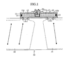
- FIG. 1 shows an embodiment in which an initiator 20 according to an embodiment of the present invention is incorporated in an inflator for use in an air bag apparatus for protecting heads of persons sitting in front and rear seats of a vehicle.
- the inflator 10 includes a mounting portion 11 a for mounting the initiator 20 and a casing 11.
- the mounting portion 11 a is located at a longitudinally central portion of the inflator 10.
- the casing 11 includes a large chamber 11 b and a small chamber 11c, which are located on the front and rear sides, respectively, of the mounting portion 11a and each contain a gas-generating material 12 and a combustion accelerator 13.
- the casing 11 is disposed along the front-rear direction of a vehicle.
- the large-volume chamber 11 b has gas outlet holes 11b1 through which gas is discharged into a front-seat-side inflation portion 31 of an air bag 30.
- the small-volume chamber 11c has gas outlet holes 11c1 through which gas is discharged into a rear-seat-side inflation portion 32 of the air bag 30.
- the gas-generating materials 12 are ignited and combust upon exposure to flame energy propagated from the initiator 20 upon ignition of the initiator 20 and are disposed in opposition to each other with respect to the initiator 20.
- the combustion accelerators 13 are highly ignitable explosive (similar to that used as an initiating explosive 25 of the initiator 20, which will be described later), accelerate combustion of the corresponding gas-generating materials 12, and are disposed in the corresponding gas-generating materials 12 at corresponding end portions (front and rear end portions within the casing 11) located away from the initiator 20.
- the initiator 20 includes a pair of electrode pins 21 a and 21b; a conductive header 22; an insulating member 23; a bridge wire 24; an initiating explosive (powder) 25; a metallic capsule 26; a resin capsule 27; and a resin mold 28.
- One electrode pin 21 a is integrally attached to the conductive header 22.
- a portion (a portion extending through and out from the resin mold 28) of the electrode pin 21 a to be connected to a connector 40 illustrated by the imaginary line in FIG. 2 extends in the vertical direction in FIG. 2 .
- the other electrode pin 21 b is integrally attached to the conductive header 22 via the insulating member 23.
- a portion (a portion extending through and out from the resin mold 28) of the electrode pin 21 b to be connected to the connector 40 extends in the vertical direction in FIG. 2 .
- the conductive header 22 is formed from an electrically conductive metal into a cylindrical shape and has a hole 22a formed therein coaxially.
- the insulating member 23 is formed into a cylindrical shape and has a through-hole 23a formed therein coaxially.
- the electrode pin 21 b is tightly fitted into the through-hole 23a to thereby be coaxially fixed in place in the insulating member 23.
- the insulating member 23 is of heat-resistant, pressure-resistant glass and is tightly fitted into the hole 22a of the conductive header 22 to thereby be coaxially fixed in place in the conductive header 22.
- the bridge wire 24 is connected to the electrode pin 21 b and to the conductive header 22, thereby indirectly bridging the electrode pins 21 a and 21 b. Upon energization through the electrode pins 21 a and 21 b, the bridge wire 24 generates heat to thereby ignite the initiating explosive 25.
- the initiating explosive 25, together with the bridge wire 24, is contained in the metallic capsule 26 in a sealed condition while being partially in contact with the bridge wire 24.
- the metallic capsule 26 is formed into a closed-bottomed tubular shape (a cuplike shape) and is configured such that the wall thickness of a tubular portion 26b is reduced as compared with that of a bottom portion 26a, whereby the tubular portion 26b is rupturable upon ignition of the initiating explosive 25.
- An opening end portion of the metallic capsule 26 is hermetically attached, through welding or the like, to the outer circumferential surface of the conductive header 22.
- Grooves 26b1 and 26b2 each having a V-shaped cross section are provided on the outer surface of the tubular portion 26b of the metallic capsule 26 at the right and left positions in FIG. 2 (two positions located in opposition to each other with respect to the axis of the tubular portion 26b).
- the grooves 26b1 and 26b2 serve as the rupture-accelerating means, the strength-weakening means, or the fragile part, for accelerating rupture of the tubular portion 26b which arises upon ignition of the initiating explosive 25.
- the resin capsule 27 is formed into a closed-bottomed tubular shape (a cuplike shape) and is fitted to the metallic capsule 26 in such a manner as to rupture when a part of the tubular portion 26b of the metallic capsule 26 ruptures upon ignition of the initiating explosive 25.
- the resin mold 28 is molded in such a manner as to integrally retain connections between component parts such as the electrode pins 21 a and 21 b, the conductive header 22, the insulating member 23, the metallic capsule 26, and the resin capsule 27.
- a connecting portion 28a for connection to the connector 40 is formed at an end portion of the resin mold 28.
- the thus-configured initiator 20 of the present embodiment operates in the following manner.
- the tubular portion 26b of the metallic capsule 26 ruptures at the two right-and-left positions (the positions where the grooves 26b1 and 26b2 are formed) in FIG. 2 .
- the resin capsule 27 ruptures, and flame propagates from the initiating explosive 25 to the opposite gas-generating materials 12 along two opposite directions, or right and left directions in FIG. 2 .
- the metallic capsule 26 of the initiator 20 assumes a closed-bottomed tubular shape composed of the bottom portion 26a and the tubular portion 26b.
- component parts of the initiator 20 can be modified as shown in FIGS. 3 to 7 .
- the following description of modified embodiments covers those component parts of the initiator 20 whose shapes are modified. Also, those component parts whose shapes remain unchanged are denoted by common reference numerals among the above-described embodiment and the modified embodiments to be described below, and repeated description thereof is omitted.
- the metallic capsule 26 of the initiator 20 includes the bottom portion 26a, the tubular portion 26b, and a corner connection portion 26c, which connects the bottom portion 26a and the tubular portion 26b.
- the wall thickness of the corner connection portion 26c is reduced as compared with that of the bottom portion 26a and that of the tubular portion 26b, whereby the corner connection portion 26c is rupturable upon ignition of the initiating explosive 25.
- Grooves 26c1 and 26c2 each having a V-shaped cross section are provided on the inclined surface of the corner connection portion 26c of the metallic capsule 26 at the right and left positions in FIG. 3 .
- the grooves 26c1 and 26c2 serve as the rupture-accelerating means, the strength-weakening means, or the fragile part, for accelerating rupture of the corner connection portion 26c which arises upon ignition of the initiating explosive 25.
- a taper portion 26a1 assuming a convex shape is formed on the bottom portion 26a such that a tip part thereof protrudes upward in FIG. 3 into the interior of the metallic capsule 26 beyond a position corresponding to the grooves 26c1 and 26c2.
- the taper portion 26a1 functions to enhance strength of the bottom portion 26a and functions as guide means for guiding detonation force induced from ignition of the initiating explosive 25 toward portions of metallic capsule 26 where the grooves 26c1 and 26c2 are formed.
- FIG. 3 operates in the following manner.
- the corner connection portion 26c of the metallic capsule 26 ruptures at the two right-and-left positions (the positions where the grooves 26c1 and 26c2 are formed) in FIG. 3 .
- the resin capsule 27 ruptures, and flame propagates from the initiating explosive 25 to the opposite gas-generating materials 12 along two directions substantially perpendicular to the inclined surface of the corner connection portion 26c.
- flame energy can be efficiently propagated from the initiating explosive 25 of the initiator 20 to the gas-generating materials 12 of the inflator 10, thereby enhancing the ignitability of the gas-generating materials 12 in the inflator 10.
- the metallic capsule 26 of the initiator 20 includes the bottom portion 26a and the tubular portion 26b and is configured such that the wall thickness of the tubular portion 26b is reduced as compared with that of the bottom portion 26a, whereby the tubular portion 26b is rupturable upon ignition of the initiating explosive 25. Also, an intermediate part of the tubular portion 26b is swollen, and grooves 26b1 and 26b2 each having a V-shaped cross section are provided on the outer surface of the swollen part at the right and left positions in FIG. 4 .
- the grooves 26b1 and 26b2 serve as the rupture-accelerating means, the strength-weakening means, or the fragile part, for accelerating rupture of the tubular portion 26b which arises upon ignition of the initiating explosive 25.
- the swollen part of the tubular portion 26b functions to reduce strength of the tubular portion 26b and functions as guide means for guiding detonation force induced from ignition of the initiating explosive 25 toward portions of metallic capsule 26 where the grooves 26b1 and 26b2 are formed.
- FIG. 4 operates in the following manner.
- the tubular portion 26b of the metallic capsule 26 ruptures at the two right-and-left positions (the positions where the grooves 26b1 and 26b2 are formed) in FIG. 4 .
- the resin capsule 27 ruptures, and flame propagates from the initiating explosive 25 to the opposite gas-generating materials 12 along two opposite directions, or right and left directions in FIG. 4 .
- the metallic capsule 26 of the initiator 20 includes the bottom portion 26a and the tubular portion 26b and is configured such that the wall thickness of the tubular portion 26b is reduced as compared with that of the bottom portion 26a, whereby the tubular portion 26b is rupturable upon ignition of the initiating explosive 25.
- Grooves 26b1 and 26b2 each having a V-shaped cross section are provided on the outer surface of the tubular portion 26b of the metallic capsule 26 at the right and left positions in FIG. 5 .
- the grooves 26b1 and 26b2 serve as the rupture-accelerating means, the strength-weakening means, or the fragile part, for accelerating rupture of the tubular portion 26b which arises upon ignition of the initiating explosive 25.
- a taper portion 26a1 assuming a convex shape is formed on the bottom portion 26a such that a tip part thereof protrudes upward in FIG. 5 into the interior of the metallic capsule 26 beyond a position corresponding to the grooves 26b1 and 26b2.
- the taper portion 26a1 functions to enhance strength of the bottom portion 26a so as to relatively weaken strength of the tubular portion 26b and functions as guide means for guiding detonation force induced from ignition of the initiating explosive 25 toward portions of metallic capsule 26 where the grooves 26b1 and 26b2 are formed.
- FIG. 5 operates in the following manner.
- the tubular portion 26b of the metallic capsule 26 ruptures at the two right-and-left positions (the positions where the grooves 26b1 and 26b2 are formed) in FIG. 5 .
- the resin capsule 27 ruptures, and flame propagates from the initiating explosive 25 to the opposite gas-generating materials 12 along two opposite directions, or right and left directions in FIG. 5 .
- the gas-generating materials 12 of the inflator 10 are disposed outside the tubular portion 26b of the metallic capsule 26, flame energy can be efficiently propagated from an ignition portion (initiating explosive 25) of the initiator 20 to the gas-generating materials 12 of the inflator 10, thereby enhancing the ignitability of the gas-generating materials 12 in the inflator 10.
- a pair of right and left bridge wires 24 can be provided.
- the metallic capsule 26 of the initiator 20 includes the bottom portion 26a and the tubular portion 26b and is configured such that the bottom portion 26a and the tubular portion 26b has substantially the same wall thickness.
- the taper portion 26a1 assuming a convex shape is formed on the bottom portion 26a in such a manner as to protrude into the interior of the metallic capsule 26.
- the taper portion 26a1 functions to enhance strength of the bottom portion 26a so as to relatively weaken strength of the tubular portion 26b and functions as guide means for guiding detonation force induced from ignition of the initiating explosive 25 toward the tubular portion 26b.
- formation of the taper portion 26a1 on the bottom portion 26b renders the amount of an initiating explosive 25b for rupturing the tubular portion 26b greater than that of an initiating explosive 25a for rupturing the bottom portion 26a, so that detonation force to be imposed on the tubular portion 26b is greater than that to be imposed on the bottom portion 26a. Therefore, upon ignition of the initiating explosives 25a and 25b contained in the metallic capsule 26, the tubular portion 26b of the metallic capsule 26 can be reliably ruptured.
- flame energy can be efficiently propagated from the initiating explosives 25a and 25b to the corresponding gas-generating materials 12 of the inflator 10, thereby enhancing the ignitability of the gas-generating materials 12 in the inflator 10.
- the initiating explosive 25b for rupturing the tubular portion 26b can be rendered greater in detonation force than the initiating explosive 25a for rupturing the bottom portion 26a, so that detonation force to be imposed on the tubular portion 26b can become greater than that to be imposed on the bottom portion 26a.
- a pair of right and left bridge wires 24 can be provided.
- portions of the electrode pins 21 a and 21 b to be connected to the connector 40 extend along the axis of the conductive header 22, the insulating member 23, the metallic capsule 26, and the resin capsule 27.
- portions of the electrode pins 21 a and 21 b to be connected to the connector 40 may extend perpendicularly to the axis of the conductive header 22, the insulating member 23, and the metallic capsule 26, whereby workability in terms of connection of the connector 40 to the electrode pins 21 a and 21 b can be enhanced.
- the resin capsule 27 is not provided, and the bottom portion 26a of the metallic capsule 26 ruptures, so that flame propagates to an inflator along the axis of the conductive header 22, the insulating member 23, and the metallic capsule 26.
- the initiator 20 upon ignition of the initiating explosive 25, flames propagates along two directions from the initiating explosive 25 to the opposite gas-generating materials 12 of the inflator 10.
- the initiator 20 may be configured such that, upon ignition of the initiating explosive 25, flame propagates along three or more directions from the initiating explosive 25 to the opposite gas-generating materials 12 of the inflator 10.
- the metallic capsule 26 and the resin capsule 27 are symmetrically formed.
- the metallic capsule 26 and the resin capsule 27 may be asymmetrically formed.
- the initiators 20 of the above-described embodiments are each incorporated in the inflator 10 for use in an air bag apparatus for protecting heads of persons sitting in front and rear seats of a vehicle.
- the initiator 20 of the present invention can be incorporated in the inflator 10 for use in a side air bag apparatus for protecting a side body region of person sitting in a vehicle.
- the above embodiments are described while mentioning the initiator 20 for use in the inflator 10 that employs the gas-generating material 12 as the gas generator.
- the initiator 20 of the present invention may be used in an inflator employing a gas generator that includes high-pressure gas and a gas seal plate for sealing in the high-pressure gas.
- detonation force induced from ignition of the initiating explosive 25 of the initiator 20 ruptures the gas seal plate, thereby releasing gas from the inflator. Therefore, the initiator 20 of the present invention can enhance a trigger action of the gas generator in the inflator.
Landscapes
- Engineering & Computer Science (AREA)
- Physics & Mathematics (AREA)
- Fluid Mechanics (AREA)
- Mechanical Engineering (AREA)
- General Engineering & Computer Science (AREA)
- Air Bags (AREA)
- Feeding, Discharge, Calcimining, Fusing, And Gas-Generation Devices (AREA)
Claims (6)
- Amorceur (20) intégré dans un dispositif de gonflage (10) et adapté pour déclencher le dispositif de gonflage (10) par la propagation d'une flamme depuis un explosif d'amorçage (25) vers un générateur de gaz (12) du dispositif de gonflage (10), caractérisé en ce que
l'amorceur (20) comprend une capsule tubulaire (26) simple à fond fermé qui possède un espace unique entouré par au moins une partie tubulaire (26b) de la capsule (26) et une partie de fond (26a) de la capsule (26) à l'intérieur de la capsule (26), laquelle capsule (26) reçoit l'explosif d'amorçage (25) dans l'espace unique,
une partie tubulaire (26b) elle même de la capsule (26) comprend une pluralité de moyens (26b1, 26b2) accélérant une rupture pour accélérer une rupture de la partie tubulaire (26b) à l'allumage de l'explosif d'amorçage (25),
la partie de fond (26a) de la capsule (26) comprend une partie à conicité (26a1), adoptant une forme convexe, qui fait saillie à l'intérieur de la capsule (26) et une pointe de la partie à conicité (26a1) possède une surface plate, et
une quantité d'une partie de l'explosif d'amorçage (25), qui est reçue dans une partie de l'espace unique entre la partie à conicité (26a1) et la partie tubulaire (26b), pour rompre la partie tubulaire (26b), est plus importante qu'une quantité d'une partie de l'explosif d'amorçage (25), qui est reçue dans une partie de l'espace unique regardant la surface plate, pour rompre la partie de fond (26a). - Amorceur (20) intégré dans un dispositif de gonflage (10) et adapté pour déclencher le dispositif de gonflage (10) par la propagation d'une flamme d'explosifs d'amorçage (25a, 25b) vers un générateur de gaz (12) du dispositif de gonflage (10), caractérisé en ce que
l'amorceur (20) comprend une capsule tubulaire (26) à fond fermé simple qui possède un espace unique entouré par au moins une partie tubulaire (26b) de la capsule (26) et une partie de fond (26a) de la capsule (26) à l'intérieur de la capsule (26), laquelle capsule (26) reçoit les explosifs d'amorçage (25a, 25b) dans l'espace unique,
la partie de fond (26a) de la capsule (26) comprend une partie à conicité (26a1) adoptant une forme convexe, qui fait saillie à l'intérieur de la capsule (26) et une pointe de la partie à conicité (26a1) possède une surface plate, et
un premier explosif d'amorçage (25b) des explosifs d'amorçage (25a, 25b), qui est reçu dans une partie de l'espace unique entre la partie à conicité (26a1) et la partie tubulaire (26b), pour rompre la partie tubulaire (26b), a une force de détonation plus importante qu'un deuxième explosif d'amorçage (25a) des explosifs d'amorçage (25a, 25b), qui est reçu dans une partie de l'espace unique regardant la surface plate, pour rompre la partie de fond (26a). - Amorceur (20) selon la revendication 1 ou 2, caractérisé en ce que l'amorceur (20) est intégré dans le dispositif de gonflage (10) au niveau d'une partie longitudinalement centrale d'un boîtier (11) du dispositif de gonflage (10), le boîtier (11) étant disposé le long de la direction avant-arrière d'un véhicule,
le dispositif de gonflage (10) est à utiliser dans un dispositif de coussin de sécurité gonflable pour protéger les têtes de personnes assises dans les sièges avant et arrières du véhicule et
le boîtier (11) possède des trous (11b1) de sortie de gaz à travers lesquels du gaz est déchargé dans une partie de gonflage côté sièges avant d'un coussin de sécurité gonflable du dispositif de coussin de sécurité gonflable au niveau d'une partie longitudinale côté avant du boîtier (11) et des trous (11c1) de sortie de gaz à travers lesquels du gaz est déchargé dans une partie de gonflage côté sièges arrières du coussin de sécurité gonflable au niveau d'une partie longitudinale côté arrière du boîtier (11). - Amorceur (20) selon la revendication 1 ou 2,
caractérisé en ce que l'amorceur (20) est intégré dans le dispositif de gonflage (10) au niveau d'une partie longitudinalement centrale d'un boîtier (11) du dispositif de gonflage (10), le boîtier (11) étant disposé le long de la direction supérieure-inférieure d'un véhicule,
le dispositif de gonflage (10) est à utiliser dans un dispositif de coussin de sécurité gonflable pour protéger une région de corps latérale d'une personne assise dans le véhicule et
le boîtier (11) possède des trous de sortie de gaz à travers lesquels du gaz est déchargé dans une partie de gonflage côté supérieur d'un coussin de sécurité gonflable du dispositif de coussin de sécurité gonflable au niveau d'une partie longitudinale côté supérieur du boîtier (11) et des trous de sortie de gaz à travers lesquels du gaz est déchargé dans une partie de gonflage côté inférieur du coussin de sécurité gonflable au niveau d'une partie longitudinale côté inférieur du boîtier (11). - Dispositif de gonflage (10) intégrant un amorceur (20) selon la revendication 1 ou 2, caractérisé en ce que
un boîtier (11) du dispositif de gonflage (10) comprend :une partie de montage (11a) destinée à monter l'amorceur (20), la partie de montage (11a) étant située au niveau d'une partie longitudinalement centrale du boîtier (11) ; etune chambre à grand volume (11b) et une chambre à petit volume (11c) qui sont situées sur les deux côtés, respectivement, de la partie de montage (11a) et dont chacune contient un matériau (12) générant du gaz et un accélérateur de combustion (13) et dont chacune possède des trous (11b1, 11c1) de sortie de gaz à travers lesquels du gaz est déchargé. - Dispositif de coussin de sécurité gonflable destiné à protéger les têtes de personnes assises dans des sièges avant et arrières d'un véhicule, intégrant un dispositif de gonflage (10) selon la revendication 5, caractérisé en ce que
le boîtier (11) du dispositif de gonflage (10) est disposé le long de la direction avant-arrière du véhicule, et
du gaz est déchargé dans une partie de gonflage (31) côté sièges avant d'un coussin de sécurité gonflable du dispositif de coussin de sécurité gonflable à travers les trous (11b1) de sortie de gaz de la chambre à grand volume (11b) et du gaz est déchargé dans une partie de gonflage (32) côté sièges arrières du coussin de sécurité gonflable à travers les trous (11c1) de sortie de gaz de la chambre à petit volume (11c).
Applications Claiming Priority (3)
| Application Number | Priority Date | Filing Date | Title |
|---|---|---|---|
| JP2002092668A JP3864823B2 (ja) | 2002-03-28 | 2002-03-28 | イニシエータ、インフレータおよび車両の乗員頭部保護エアバッグ装置 |
| JP2002092668 | 2002-03-28 | ||
| PCT/JP2003/003147 WO2003083403A1 (fr) | 2002-03-28 | 2003-03-17 | Amorceur |
Publications (3)
| Publication Number | Publication Date |
|---|---|
| EP1489376A1 EP1489376A1 (fr) | 2004-12-22 |
| EP1489376A4 EP1489376A4 (fr) | 2005-12-28 |
| EP1489376B1 true EP1489376B1 (fr) | 2010-05-26 |
Family
ID=28671718
Family Applications (1)
| Application Number | Title | Priority Date | Filing Date |
|---|---|---|---|
| EP03712718A Expired - Lifetime EP1489376B1 (fr) | 2002-03-28 | 2003-03-17 | Amorceur |
Country Status (8)
| Country | Link |
|---|---|
| US (1) | US7357083B2 (fr) |
| EP (1) | EP1489376B1 (fr) |
| JP (1) | JP3864823B2 (fr) |
| KR (1) | KR100656577B1 (fr) |
| CN (1) | CN100363706C (fr) |
| AU (1) | AU2003221006A1 (fr) |
| DE (1) | DE60332709D1 (fr) |
| WO (1) | WO2003083403A1 (fr) |
Families Citing this family (45)
| Publication number | Priority date | Publication date | Assignee | Title |
|---|---|---|---|---|
| JP2005225346A (ja) * | 2004-02-12 | 2005-08-25 | Daicel Chem Ind Ltd | エアバッグ用インフレータ |
| US7316187B2 (en) * | 2004-09-17 | 2008-01-08 | Autoliv Asp, Inc. | Radial discharge actuator device |
| JP2007015675A (ja) * | 2005-06-08 | 2007-01-25 | Daicel Chem Ind Ltd | エアバッグ用ガス発生器 |
| US7780193B2 (en) | 2005-09-30 | 2010-08-24 | Toyoda Gosei Co., Ltd. | Gas generator |
| JP4967154B2 (ja) | 2005-09-30 | 2012-07-04 | 日本化薬株式会社 | ガス発生器 |
| JP2007098991A (ja) * | 2005-09-30 | 2007-04-19 | Toyoda Gosei Co Ltd | サイドエアバッグ装置 |
| DE102005058721A1 (de) * | 2005-12-08 | 2007-06-14 | Trw Airbag Systems Gmbh | Pyrotechnische Aktuatoreinheit sowie Gassackmodul mit einer solchen Akruatoreinheit |
| JP5044982B2 (ja) * | 2006-05-16 | 2012-10-10 | タカタ株式会社 | イニシエータ、インフレータ及びエアバッグ装置 |
| JP5044983B2 (ja) * | 2006-05-16 | 2012-10-10 | タカタ株式会社 | イニシエータ、インフレータ及びエアバッグ装置 |
| US7908970B1 (en) * | 2007-11-13 | 2011-03-22 | Sandia Corporation | Dual initiation strip charge apparatus and methods for making and implementing the same |
| US7845277B2 (en) * | 2008-05-28 | 2010-12-07 | Autoliv Asp, Inc. | Header assembly |
| GB2491225B (en) * | 2010-03-16 | 2013-05-01 | Qinetiq Ltd | MEMS detonator |
| US20120234193A1 (en) | 2011-03-17 | 2012-09-20 | Special Devices, Inc. | Igniter with a locked consolidated powder charge |
| US8925461B2 (en) * | 2011-09-22 | 2015-01-06 | Eaglepicher Technologies, Llc | Low profile igniter |
| US8661985B2 (en) * | 2012-04-18 | 2014-03-04 | Autoliv Asp, Inc. | Low-profile igniter assemblies adapted for use with inflatable airbag systems |
| DE102012023877A1 (de) * | 2012-12-06 | 2014-06-12 | Trw Airbag Systems Gmbh | Pyrotechnische aktuatorbaugruppe sowie gassackmodul mit einer solchen aktuatorbaugruppe |
| US12203350B2 (en) | 2013-07-18 | 2025-01-21 | DynaEnergetics Europe GmbH | Detonator positioning device |
| US9702680B2 (en) | 2013-07-18 | 2017-07-11 | Dynaenergetics Gmbh & Co. Kg | Perforation gun components and system |
| CN109372475B (zh) | 2013-08-26 | 2021-05-18 | 德国德力能有限公司 | 射孔枪和雷管组件 |
| CA2941648C (fr) | 2014-03-07 | 2022-08-16 | Dynaenergetics Gmbh & Co. Kg | Dispositif et procede de positionnement d'un detonateur dans un ensemble perforateur |
| EP3140503B1 (fr) * | 2014-05-05 | 2024-04-03 | DynaEnergetics GmbH & Co. KG | Ensemble tête d'initiateur |
| FR3030715B1 (fr) * | 2014-12-22 | 2017-02-03 | Ncs Pyrotechnie Et Tech Sas | Etui d'allumeur |
| FR3045145B1 (fr) | 2015-12-15 | 2018-06-29 | Autoliv Development Ab | Allumeur pyrotechnique |
| JP6742218B2 (ja) * | 2016-05-23 | 2020-08-19 | 日本化薬株式会社 | 点火器組立体の製造方法 |
| US10760880B2 (en) * | 2017-06-22 | 2020-09-01 | Autoliv Development Ab | Igniter case |
| US10458213B1 (en) | 2018-07-17 | 2019-10-29 | Dynaenergetics Gmbh & Co. Kg | Positioning device for shaped charges in a perforating gun module |
| US10386168B1 (en) | 2018-06-11 | 2019-08-20 | Dynaenergetics Gmbh & Co. Kg | Conductive detonating cord for perforating gun |
| US11808093B2 (en) | 2018-07-17 | 2023-11-07 | DynaEnergetics Europe GmbH | Oriented perforating system |
| WO2022084363A1 (fr) | 2020-10-20 | 2022-04-28 | DynaEnergetics Europe GmbH | Canon de perforation et ensemble d'alignement |
| US11339614B2 (en) | 2020-03-31 | 2022-05-24 | DynaEnergetics Europe GmbH | Alignment sub and orienting sub adapter |
| USD1034879S1 (en) | 2019-02-11 | 2024-07-09 | DynaEnergetics Europe GmbH | Gun body |
| USD1019709S1 (en) | 2019-02-11 | 2024-03-26 | DynaEnergetics Europe GmbH | Charge holder |
| USD1010758S1 (en) | 2019-02-11 | 2024-01-09 | DynaEnergetics Europe GmbH | Gun body |
| US11946728B2 (en) | 2019-12-10 | 2024-04-02 | DynaEnergetics Europe GmbH | Initiator head with circuit board |
| WO2021122797A1 (fr) | 2019-12-17 | 2021-06-24 | DynaEnergetics Europe GmbH | Système de perforateur modulaire |
| USD1041608S1 (en) | 2020-03-20 | 2024-09-10 | DynaEnergetics Europe GmbH | Outer connector |
| US11988049B2 (en) | 2020-03-31 | 2024-05-21 | DynaEnergetics Europe GmbH | Alignment sub and perforating gun assembly with alignment sub |
| US12366142B2 (en) | 2021-03-03 | 2025-07-22 | DynaEnergetics Europe GmbH | Modular perforating gun system |
| WO2022184732A1 (fr) | 2021-03-03 | 2022-09-09 | DynaEnergetics Europe GmbH | Cloison et adaptateur d'étanchéité double |
| US11732556B2 (en) | 2021-03-03 | 2023-08-22 | DynaEnergetics Europe GmbH | Orienting perforation gun assembly |
| US11713625B2 (en) | 2021-03-03 | 2023-08-01 | DynaEnergetics Europe GmbH | Bulkhead |
| US12000267B2 (en) | 2021-09-24 | 2024-06-04 | DynaEnergetics Europe GmbH | Communication and location system for an autonomous frack system |
| US12253339B2 (en) | 2021-10-25 | 2025-03-18 | DynaEnergetics Europe GmbH | Adapter and shaped charge apparatus for optimized perforation jet |
| US12312925B2 (en) | 2021-12-22 | 2025-05-27 | DynaEnergetics Europe GmbH | Manually oriented internal shaped charge alignment system and method of use |
| US12546194B2 (en) | 2023-08-04 | 2026-02-10 | DynaEnergetics Europe GmbH | Method and apparatus for automatic arming of perforating gun |
Family Cites Families (23)
| Publication number | Priority date | Publication date | Assignee | Title |
|---|---|---|---|---|
| JPH02144857A (ja) | 1988-11-25 | 1990-06-04 | Hitachi Ltd | 燃料電池及びその分解方法 |
| US5005486A (en) * | 1989-02-03 | 1991-04-09 | Trw Vehicle Safety Systems Inc. | Igniter for airbag propellant grains |
| JPH02144857U (fr) * | 1989-05-11 | 1990-12-07 | ||
| FR2698687B1 (fr) * | 1992-12-01 | 1995-02-03 | Giat Ind Sa | Initiateur pyrotechnique. |
| US5531473A (en) * | 1994-05-31 | 1996-07-02 | Morton International, Inc. | Fluid fuel-containing initiator device for an air bag inflator |
| US5603525A (en) * | 1995-06-22 | 1997-02-18 | Trw Inc. | Air bag inflator initiator housing with stored fluid pressure relief |
| US5678856A (en) * | 1995-06-28 | 1997-10-21 | Trw Inc. | Exploding foil initiator for air bag inflator |
| JPH10213397A (ja) | 1997-01-30 | 1998-08-11 | Japan Steel Works Ltd:The | 起爆方法及び装置 |
| DE19733353C1 (de) | 1997-08-01 | 1998-12-10 | Nico Pyrotechnik | Zündeinrichtung für eine Insassenschutzvorrichtung eines Kraftfahrzeuges |
| JP3702074B2 (ja) | 1997-08-25 | 2005-10-05 | 日本化薬株式会社 | ガス発生器 |
| JPH1191495A (ja) | 1997-09-18 | 1999-04-06 | Nippon Kayaku Co Ltd | ガス発生器 |
| FR2772909B1 (fr) | 1997-12-22 | 2000-01-28 | Livbag Snc | Initiateur electro-pyrotechnique a trois connexions electriques |
| JP2000168487A (ja) | 1998-02-12 | 2000-06-20 | Denso Corp | インフレ―タ |
| JP2971439B2 (ja) | 1998-04-21 | 1999-11-08 | 東芝ホクト電子株式会社 | 着火装置およびその製造方法 |
| US6295935B1 (en) * | 1998-04-27 | 2001-10-02 | Trw Inc. | Initiator for air bag inflator |
| US6116642A (en) * | 1998-04-27 | 2000-09-12 | Trw Inc. | Inflator for inflating an inflatable vehicle occupant protection device |
| FR2788846B1 (fr) * | 1999-01-25 | 2001-10-26 | Livbag Snc | Generateur de gaz hybride muni d'un initiateur a chargement explosif profile |
| KR20010002053A (ko) | 1999-06-10 | 2001-01-05 | 총엔류 | 장약 조성물과 그것을 포함한 점화기 |
| JP2001021293A (ja) | 1999-07-02 | 2001-01-26 | Nippon Kayaku Co Ltd | スクイブ、及びスクイブの製造方法 |
| DE10036455C2 (de) * | 2000-07-26 | 2002-06-20 | Willi Luebbers | Zündeinrichtung mit einer Sollburchstelle für einen Treibsatz des Gasgenerators einer Insassenschutzvorrichtung in Kraftfahrzeugen |
| DE10111715A1 (de) * | 2001-03-12 | 2002-10-02 | Nico Pyrotechnik | Anzündvorrichtung für die Treibladung einer Insassenschutzvorrichtung |
| JP3906910B2 (ja) * | 2002-03-29 | 2007-04-18 | トヨタ自動車株式会社 | イニシエータ |
| US6923122B2 (en) * | 2002-12-10 | 2005-08-02 | Reynolds Systems, Inc. | Energetic material initiation device utilizing exploding foil initiated ignition system with secondary explosive material |
-
2002
- 2002-03-28 JP JP2002092668A patent/JP3864823B2/ja not_active Expired - Fee Related
-
2003
- 2003-03-17 KR KR1020047015329A patent/KR100656577B1/ko not_active Expired - Fee Related
- 2003-03-17 AU AU2003221006A patent/AU2003221006A1/en not_active Abandoned
- 2003-03-17 DE DE60332709T patent/DE60332709D1/de not_active Expired - Lifetime
- 2003-03-17 WO PCT/JP2003/003147 patent/WO2003083403A1/fr not_active Ceased
- 2003-03-17 CN CNB038073110A patent/CN100363706C/zh not_active Expired - Fee Related
- 2003-03-17 EP EP03712718A patent/EP1489376B1/fr not_active Expired - Lifetime
- 2003-03-17 US US10/509,242 patent/US7357083B2/en not_active Expired - Fee Related
Also Published As
| Publication number | Publication date |
|---|---|
| KR100656577B1 (ko) | 2006-12-11 |
| AU2003221006A1 (en) | 2003-10-13 |
| DE60332709D1 (de) | 2010-07-08 |
| CN1643332A (zh) | 2005-07-20 |
| CN100363706C (zh) | 2008-01-23 |
| EP1489376A4 (fr) | 2005-12-28 |
| US7357083B2 (en) | 2008-04-15 |
| JP3864823B2 (ja) | 2007-01-10 |
| EP1489376A1 (fr) | 2004-12-22 |
| JP2003287400A (ja) | 2003-10-10 |
| US20050115453A1 (en) | 2005-06-02 |
| WO2003083403A1 (fr) | 2003-10-09 |
| KR20040105806A (ko) | 2004-12-16 |
Similar Documents
| Publication | Publication Date | Title |
|---|---|---|
| US7357083B2 (en) | Initiator | |
| KR100548886B1 (ko) | 가스 생성 장치 | |
| KR100591689B1 (ko) | 다중 이니시에이터를 가진 인플레이터 | |
| JP3316200B2 (ja) | ハイブリッドガスジェネレータおよび電気火花点火装置 | |
| US8870222B2 (en) | Gas generator | |
| EP0978423B1 (fr) | Dispositif de production de gaz destine a un coussin gonflable et procede de gonflage de ce coussin | |
| KR19980087274A (ko) | 관형 연소실을 가진 에어백용 적응성 파이러테크닉 가스 발생기 | |
| WO2001031281A1 (fr) | Amorceur de type electrique et generateur de gaz | |
| US12319224B2 (en) | Integral ignition structure and compressed-gas-type fuel gas generator | |
| CN1320329C (zh) | 起爆器 | |
| KR0163804B1 (ko) | 자동차 탑승자 구속장치를 팽창시키기 위한 장치 | |
| US7293797B2 (en) | Inflator | |
| EP1352793B1 (fr) | Gonfleur | |
| US6572143B2 (en) | Air bag gas inflator | |
| JP2008517245A (ja) | 脆弱領域を含む起爆装置 | |
| JP2002308040A (ja) | ガス発生器 | |
| JP5242228B2 (ja) | 人員拘束装置用ガス発生器 | |
| JP4127280B2 (ja) | インフレータ | |
| EP1559621A2 (fr) | Gonfleur hybride | |
| JP2026039654A (ja) | ハイブリッドインフレーター | |
| KR950008203Y1 (ko) | 압축가스식 에어백(Air Bag)용 인플레터 아세이(Inflator Ass'y) |
Legal Events
| Date | Code | Title | Description |
|---|---|---|---|
| PUAI | Public reference made under article 153(3) epc to a published international application that has entered the european phase |
Free format text: ORIGINAL CODE: 0009012 |
|
| 17P | Request for examination filed |
Effective date: 20041007 |
|
| AK | Designated contracting states |
Kind code of ref document: A1 Designated state(s): AT BE BG CH CY CZ DE DK EE ES FI FR GB GR HU IE IT LI LU MC NL PT RO SE SI SK TR |
|
| AX | Request for extension of the european patent |
Extension state: AL LT LV MK |
|
| A4 | Supplementary search report drawn up and despatched |
Effective date: 20051110 |
|
| 17Q | First examination report despatched |
Effective date: 20061031 |
|
| GRAP | Despatch of communication of intention to grant a patent |
Free format text: ORIGINAL CODE: EPIDOSNIGR1 |
|
| GRAS | Grant fee paid |
Free format text: ORIGINAL CODE: EPIDOSNIGR3 |
|
| GRAA | (expected) grant |
Free format text: ORIGINAL CODE: 0009210 |
|
| GRAC | Information related to communication of intention to grant a patent modified |
Free format text: ORIGINAL CODE: EPIDOSCIGR1 |
|
| AK | Designated contracting states |
Kind code of ref document: B1 Designated state(s): CZ DE FR GB IT |
|
| REG | Reference to a national code |
Ref country code: GB Ref legal event code: FG4D |
|
| REF | Corresponds to: |
Ref document number: 60332709 Country of ref document: DE Date of ref document: 20100708 Kind code of ref document: P |
|
| PLBE | No opposition filed within time limit |
Free format text: ORIGINAL CODE: 0009261 |
|
| STAA | Information on the status of an ep patent application or granted ep patent |
Free format text: STATUS: NO OPPOSITION FILED WITHIN TIME LIMIT |
|
| 26N | No opposition filed |
Effective date: 20110301 |
|
| REG | Reference to a national code |
Ref country code: DE Ref legal event code: R097 Ref document number: 60332709 Country of ref document: DE Effective date: 20110228 |
|
| REG | Reference to a national code |
Ref country code: GB Ref legal event code: 746 Effective date: 20121219 |
|
| REG | Reference to a national code |
Ref country code: DE Ref legal event code: R084 Ref document number: 60332709 Country of ref document: DE Effective date: 20121213 |
|
| REG | Reference to a national code |
Ref country code: FR Ref legal event code: PLFP Year of fee payment: 13 |
|
| PGFP | Annual fee paid to national office [announced via postgrant information from national office to epo] |
Ref country code: DE Payment date: 20150310 Year of fee payment: 13 Ref country code: CZ Payment date: 20150305 Year of fee payment: 13 Ref country code: IT Payment date: 20150220 Year of fee payment: 13 |
|
| PGFP | Annual fee paid to national office [announced via postgrant information from national office to epo] |
Ref country code: GB Payment date: 20150311 Year of fee payment: 13 Ref country code: FR Payment date: 20150309 Year of fee payment: 13 |
|
| REG | Reference to a national code |
Ref country code: DE Ref legal event code: R119 Ref document number: 60332709 Country of ref document: DE |
|
| GBPC | Gb: european patent ceased through non-payment of renewal fee |
Effective date: 20160317 |
|
| PG25 | Lapsed in a contracting state [announced via postgrant information from national office to epo] |
Ref country code: CZ Free format text: LAPSE BECAUSE OF NON-PAYMENT OF DUE FEES Effective date: 20160317 |
|
| REG | Reference to a national code |
Ref country code: FR Ref legal event code: ST Effective date: 20161130 |
|
| PG25 | Lapsed in a contracting state [announced via postgrant information from national office to epo] |
Ref country code: GB Free format text: LAPSE BECAUSE OF NON-PAYMENT OF DUE FEES Effective date: 20160317 Ref country code: FR Free format text: LAPSE BECAUSE OF NON-PAYMENT OF DUE FEES Effective date: 20160331 Ref country code: DE Free format text: LAPSE BECAUSE OF NON-PAYMENT OF DUE FEES Effective date: 20161001 |
|
| PG25 | Lapsed in a contracting state [announced via postgrant information from national office to epo] |
Ref country code: IT Free format text: LAPSE BECAUSE OF NON-PAYMENT OF DUE FEES Effective date: 20160317 |