EP1489390A2 - Mesure de phase dans un dispositif de mesure - Google Patents
Mesure de phase dans un dispositif de mesure Download PDFInfo
- Publication number
- EP1489390A2 EP1489390A2 EP04253212A EP04253212A EP1489390A2 EP 1489390 A2 EP1489390 A2 EP 1489390A2 EP 04253212 A EP04253212 A EP 04253212A EP 04253212 A EP04253212 A EP 04253212A EP 1489390 A2 EP1489390 A2 EP 1489390A2
- Authority
- EP
- European Patent Office
- Prior art keywords
- signal
- phase
- measurement device
- numerically
- digitised
- Prior art date
- Legal status (The legal status is an assumption and is not a legal conclusion. Google has not performed a legal analysis and makes no representation as to the accuracy of the status listed.)
- Withdrawn
Links
Images

Classifications
-
- G—PHYSICS
- G01—MEASURING; TESTING
- G01F—MEASURING VOLUME, VOLUME FLOW, MASS FLOW OR LIQUID LEVEL; METERING BY VOLUME
- G01F1/00—Measuring the volume flow or mass flow of fluid or fluent solid material wherein the fluid passes through a meter in a continuous flow
- G01F1/76—Devices for measuring mass flow of a fluid or a fluent solid material
- G01F1/78—Direct mass flowmeters
- G01F1/80—Direct mass flowmeters operating by measuring pressure, force, momentum, or frequency of a fluid flow to which a rotational movement has been imparted
- G01F1/84—Coriolis or gyroscopic mass flowmeters
- G01F1/8409—Coriolis or gyroscopic mass flowmeters constructional details
- G01F1/8431—Coriolis or gyroscopic mass flowmeters constructional details electronic circuits
-
- G—PHYSICS
- G01—MEASURING; TESTING
- G01F—MEASURING VOLUME, VOLUME FLOW, MASS FLOW OR LIQUID LEVEL; METERING BY VOLUME
- G01F1/00—Measuring the volume flow or mass flow of fluid or fluent solid material wherein the fluid passes through a meter in a continuous flow
- G01F1/56—Measuring the volume flow or mass flow of fluid or fluent solid material wherein the fluid passes through a meter in a continuous flow by using electric or magnetic effects
- G01F1/58—Measuring the volume flow or mass flow of fluid or fluent solid material wherein the fluid passes through a meter in a continuous flow by using electric or magnetic effects by electromagnetic flowmeters
- G01F1/60—Circuits therefor
-
- G—PHYSICS
- G01—MEASURING; TESTING
- G01F—MEASURING VOLUME, VOLUME FLOW, MASS FLOW OR LIQUID LEVEL; METERING BY VOLUME
- G01F1/00—Measuring the volume flow or mass flow of fluid or fluent solid material wherein the fluid passes through a meter in a continuous flow
- G01F1/76—Devices for measuring mass flow of a fluid or a fluent solid material
- G01F1/78—Direct mass flowmeters
- G01F1/80—Direct mass flowmeters operating by measuring pressure, force, momentum, or frequency of a fluid flow to which a rotational movement has been imparted
- G01F1/84—Coriolis or gyroscopic mass flowmeters
-
- G—PHYSICS
- G01—MEASURING; TESTING
- G01F—MEASURING VOLUME, VOLUME FLOW, MASS FLOW OR LIQUID LEVEL; METERING BY VOLUME
- G01F1/00—Measuring the volume flow or mass flow of fluid or fluent solid material wherein the fluid passes through a meter in a continuous flow
- G01F1/76—Devices for measuring mass flow of a fluid or a fluent solid material
- G01F1/78—Direct mass flowmeters
- G01F1/80—Direct mass flowmeters operating by measuring pressure, force, momentum, or frequency of a fluid flow to which a rotational movement has been imparted
- G01F1/84—Coriolis or gyroscopic mass flowmeters
- G01F1/8409—Coriolis or gyroscopic mass flowmeters constructional details
- G01F1/8436—Coriolis or gyroscopic mass flowmeters constructional details signal processing
-
- G—PHYSICS
- G01—MEASURING; TESTING
- G01F—MEASURING VOLUME, VOLUME FLOW, MASS FLOW OR LIQUID LEVEL; METERING BY VOLUME
- G01F1/00—Measuring the volume flow or mass flow of fluid or fluent solid material wherein the fluid passes through a meter in a continuous flow
- G01F1/76—Devices for measuring mass flow of a fluid or a fluent solid material
- G01F1/78—Direct mass flowmeters
- G01F1/80—Direct mass flowmeters operating by measuring pressure, force, momentum, or frequency of a fluid flow to which a rotational movement has been imparted
- G01F1/84—Coriolis or gyroscopic mass flowmeters
- G01F1/845—Coriolis or gyroscopic mass flowmeters arrangements of measuring means, e.g., of measuring conduits
- G01F1/8468—Coriolis or gyroscopic mass flowmeters arrangements of measuring means, e.g., of measuring conduits vibrating measuring conduits
- G01F1/849—Coriolis or gyroscopic mass flowmeters arrangements of measuring means, e.g., of measuring conduits vibrating measuring conduits having straight measuring conduits
Definitions
- the present invention relates to measuring devices, in preferred embodiments to electromagnetic flow meters or Coriolis mass flow meters.
- flow meter is intended to encompass flow meters for measuring flow of a liquid.
- Electromagnetic flow meters are well known in the art. Very briefly, in an electromagnetic flow meter one or more excitation coil(s) are arranged in or around a measurement duct for generating a magnetic field across the fluid flowing through the measurement duct. This causes electric charges within the fluid to be displaced transversely to the direction of the magnetic field and the direction of flow, which results in a potential difference between opposite sides of the measurement duct. This potential difference can be measured and provides an indication of the flow through the measurement duct.
- the measured signal will also generally be an AC signal.
- Coriolis mass flow meters are known for example from US 4,422,338, US 5,423,221, US 4,856,346, US 5,394,758, US 4,192,184 and US re-issue patent 31450, the disclosures of each of which are herein incorporated by reference.
- a measurement duct is caused to oscillate, for example by twisting the duct by means of AC electromagnetic excitation.
- This displacement of the measurement duct at various positions along the duct is indicative of mass flow through the measurement duct.
- the measured signal indicative of displacement will also generally be of AC nature.
- phase sensitive detectors can be used to improve accuracy.
- phase locked loops may also be used.
- Modern measuring devices often include a digital signal processor (DSP) for digitally generating an excitation signal, digitally filtering a measured signal and this can be used to carry out digital zero-crossing detection and peak detection.
- DSP digital signal processor
- the present invention provides a method of determining the phase of a signal in a measurement device having a digital signal processor, comprising digitising the signal; numerically correlating the digitised signal or a signal derived therefrom with a numerically generated reference signal having a reference phase; and determining the phase from the result of the correlation.
- Correlating the measured signal with a numerically generated reference signal not only has the advantage that, unlike in the zero-crossing and peak detection approaches, no information is lost, but also that rejection of other signal components may be surprisingly enhanced when compared with employing a measured reference signal such as a measured value of the current through the excitation coils (in the case of an electromagnetic flow meter).
- a measured reference signal such as a measured value of the current through the excitation coils (in the case of an electromagnetic flow meter).
- the technique according to the present invention may enable more accurate measurements to be obtained than with a technique which employs zero-crossing or peak detection. This is so despite the fact that the reference signal used pursuant to the present invention is not representative of a "real signal".
- the amplitude of the signal may be determined from the result of the correlation.
- the numerically generated reference signal comprises a sinusoidal signal.
- the digitised signal or a signal derived therefrom is numerically correlated with numerically generated first and second reference signals having a quadrature phase relation.
- the reference signal or, in the case of two or more reference signals at least one of them, has a predetermined phase.
- the reference signal or, in the case of two or more reference signals at least one of them, has the same frequency and phase as a further signal used for operating the measurement device.
- an estimate ⁇ L of the phase of the digitised signal is provided, wherein the reference signal or, in the case of two or more reference signals at least one of them, has the same frequency as a further signal used for operating the measurement device, and a phase corresponding to the estimated phase ⁇ L.
- the estimate of the phase ⁇ L may be provided by calibrating the device.
- the measurement device may be a flow meter, for example a Coriolis meter or an electromagnetic flow meter.
- the further signal is preferably an AC excitation signal used for operating the flow meter.
- a measure of flow rate is preferably determined based on said phase.
- the invention provides a method of processing a signal in a measurement device having a digital signal processor, comprising digitising the signal; and numerically correlating the digitised signal or a signal derived therefrom with a numerically generated reference signal, wherein the reference signal has a predetermined phase.
- an estimate ⁇ L of the phase of the digitised signal is provided, wherein the reference signal has the same frequency as a further signal used for operating the measurement device, and a phase corresponding to the estimated phase ⁇ L.
- the estimate of the phase ⁇ L may be provided by calibrating the device.
- the amplitude is determined from the result of the correlation.
- the measurement device is a flow meter, and a measure of flow rate is preferably determined based on said amplitude.
- the invention provides a measurement device comprising means for digitising a signal; means for numerically correlating the digitised signal or a signal derived therefrom with a numerically generated reference signal; and means for determining the phase of the signal from the result of the correlation.
- the invention provides a measurement device comprising means for digitising a signal; and means for numerically correlating the digitised signal or a signal derived therefrom with a numerically generated reference signal having a predetermined phase.
- the invention provides a computer program suitable for determining the phase of a signal in a measurement device having a digital signal processor, comprising computer code for digitising the signal; computer code for numerically correlating the digitised signal or a signal derived therefrom with a numerically generated reference signal; and computer code for determining the phase from the result of the correlation.
- the invention provides a computer program suitable for processing a signal in a measurement device having a digital signal processor, comprising computer code for digitising the signal; and computer code for numerically correlating the digitised signal or a signal derived therefrom with a numerically generated reference signal having a predetermined phase.
- the invention also provides a computer program product comprising a computer readable medium which stores the computer program according to the fifth or sixth aspect.
- Apparatus, computer program and computer program product aspects corresponding to the subordinate method aspects are also provided. Preferable features of one aspect may be applied to other aspects.
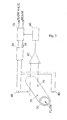
- twisting mechanism 140 causes duct 130 to oscillate about its axis over its entire length, although the angular displacement is generally smaller towards the ends than towards the middle.
- the angular displacement of the measurement duct 130 can be measured at various positions. In the example shown two displacement sensors 150 are shown, but in principle the invention can be carried out with only one displacement sensor. Likewise, further displacement sensors can be added along the measurement duct.
- the displacement as sensed by displacement sensor 150 is passed to DSP 70 after analogue to digital conversion in ADC 60.
- the Analogue to digital converter 60 may be integrated into the DSP 70.
- the sensed signal may be amplified in amplifier 65.
- DSP 70 correlates the digital representation of the measured displacement signal with the reference signal 10 so as to provide as an output the flow rate through measurement duct 130 and optionally also the phase of the measured displacement signal with respect to the reference signal 10.
- C S 1 ⁇ 2 (Acos ⁇ )
- C C 1 ⁇ 2 (Asin ⁇ ).
- phase ⁇ is known a measure of the flow can be calculated, as is known in the art.
- the electromagnetic flow meter in a Coriolis meter this may be used for example for controlling the amplitude of the signal which drives twisting mechanism 140.
- the electromagnetic flow meter according to the second embodiment also comprises a DSP 70, a current source 20 and an ADC 60, which perform the same or corresponding functions as in the first embodiment.
- the electromagnetic flow meter comprises a measurement duct 30 through which for example a liquid flows.
- An AC magnetic field B is generated by field generating coils 40, which are energised by current from amplifier 20.
- Digital signal processor (DSP) 70 generates a digital control signal 10, which is amplified by amplifier 20 so as to drive the coils 40.
- amplifier 20 may be redundant or integrated into DSP 70.
- the potential difference within the measurement duct 30 is sensed by sensing electrodes 50 arranged in or on the walls of the measurement duct 30.
- the sensed signal is passed to the DSP 70 after analogue to digital conversion in ADC 60 and optionally amplification by amplifier 65.
- DSP 70 correlates the digital representation of the sensed signal of the potential difference within the measurement duct 30 with the signal 10.
- DSP 70 outputs a value indicative of the flow rate through the measurement duct 30, and optionally also the phase ⁇ .
- the correlation processing in the second embodiment may be performed in analogy with the correlation processing described in the first embodiment, although in the case of an electromagnetic flowmeter in an electromagnetic flowmeter it is the amplitude A of the measured signal which is directly representative of flow rate, and not the phase ⁇ . Hence by providing A as an output (if necessary after multiplication with an appropriate scaling factor) an indication of flow rate is provided.
- the amplitude A (a measure of flow rate) can be calculated according to Equation 7.
- a first development of the above technique is based on the appreciation that for some measuring devices an estimate of the phase between an excitation signal and the measured signal can be used in the correlation, which may improve measurement accuracy.
- the voltage sensed by sensing electrodes 50 will normally lag by a small amount behind the excitation signal which energises coils 40 (which in turn should be in phase with control signal 10).
- the phase ⁇ L corresponding to this lag can be estimated for example by carrying out a calibration run, or by a zero-crossing or peak detection method. Note that the advantages of the present invention are not lost by using zero-crossing or peak detection here. They are used merely to provide an estimate of the phase ⁇ L .
- the correlation is carried out in accordance with the principles of the present invention.
- sin ⁇ t and cos ⁇ t are replaced by sin( ⁇ t- ⁇ L ) and cos( ⁇ t- ⁇ L).
- the sensed signal is correlated with a (numerically generated) signal having approximately the same phase as the sensed signal. This may improve rejection of unwanted signal components, in particular signal components which have a quadrature phase relationship with the wanted signal.
- the amplitude of the sensed signal provides an indication of flow rate, whereas the phase does not. In this case it may still be advantageous to estimate the phase ⁇ L., because the correlation can then be carried out with a reference signal having approximately the same phase as the sensed signal.
- the amplitude of the sensed signal is again calculated according to Equation 7.
- phase of the reference signal should be chosen so as to be (approximately) the same as the phase of the sensed signal.
- the phase of the sensed signal is estimated, for example by means of a calibration run, or can be determined using a look-up table (in the case of an electromagnetic flowmeter of known configuration the phase of the sensed signal associated with a particular excitation frequency and excitation current amplitude can usually be calculated in advance, and the results of the calculation can be stored in a memory for future reference). Correlating with a reference signal whose phase is (approximately) the same as the phase of the sensed signal effectively results in phase-sensitive detection of the sensed signal.
- a lag i.e. a phase difference
- maximum field lacks maximum current
- unwanted signal components which are in phase quadrature with the wanted components.
- eddy currents e.g. in the sensing electrodes 50 having a phase of approximately 90° with respect to the wanted signal.
- both the finite response time and the quadrature phase signal components should be taken into account.
- the contribution due to eddy currents can be determined in a calibration run, i.e. at zero flow or with an empty pipe, and the results can be stored so that they can be taken into account in non-zero flow measurements.
- phase due to the coil response can then be determined in further calibration runs, at non-zero flow.
- Calibration at different (known) flow rates enables various phases to be determined (e.g. as described above according to Equations 2 to 6).
- a look-up table can be generated which links a particular excitation frequency and amplitude of excitation current to an expected phase of a measured signal with respect to the excitation current.
- phase sensitive detection can be carried out.
Landscapes
- Physics & Mathematics (AREA)
- Fluid Mechanics (AREA)
- General Physics & Mathematics (AREA)
- Electromagnetism (AREA)
- Engineering & Computer Science (AREA)
- Signal Processing (AREA)
- Measuring Volume Flow (AREA)
- Measuring Phase Differences (AREA)
Applications Claiming Priority (2)
| Application Number | Priority Date | Filing Date | Title |
|---|---|---|---|
| GB0312471A GB2402222B (en) | 2003-05-30 | 2003-05-30 | Phase measurement in measuring device |
| GB0312471 | 2003-05-30 |
Publications (2)
| Publication Number | Publication Date |
|---|---|
| EP1489390A2 true EP1489390A2 (fr) | 2004-12-22 |
| EP1489390A3 EP1489390A3 (fr) | 2007-06-06 |
Family
ID=9959065
Family Applications (1)
| Application Number | Title | Priority Date | Filing Date |
|---|---|---|---|
| EP04253212A Withdrawn EP1489390A3 (fr) | 2003-05-30 | 2004-05-28 | Mesure de phase dans un dispositif de mesure |
Country Status (3)
| Country | Link |
|---|---|
| US (1) | US7110899B2 (fr) |
| EP (1) | EP1489390A3 (fr) |
| GB (1) | GB2402222B (fr) |
Cited By (6)
| Publication number | Priority date | Publication date | Assignee | Title |
|---|---|---|---|---|
| DE102004055553A1 (de) * | 2004-11-17 | 2006-05-18 | Endress + Hauser Flowtec Ag | Mess- und Betriebsschaltung für einen Coriolis-Massedurchflussmesser mit drei Messkanälen |
| DE102005025395A1 (de) * | 2005-05-31 | 2006-12-07 | Endress + Hauser Flowtec Ag | Coriolis Durchflussmesser und Verfahren zur Durchflussmessung |
| US7289917B2 (en) | 2005-05-31 | 2007-10-30 | Endress +Hasuer Flowtec Ag | Coriolis flow meter and method for flow measurement |
| US7877220B2 (en) | 2007-07-26 | 2011-01-25 | Abb Limited | Flowmeter |
| EP1907802A4 (fr) * | 2005-07-11 | 2011-06-22 | Invensys Sys Inc | Techniques de traitement en mode coriolis |
| RU2486529C2 (ru) * | 2011-08-31 | 2013-06-27 | Федеральное государственное автономное образовательное учреждение высшего профессионального образования "ЮЖНЫЙ ФЕДЕРАЛЬНЫЙ УНИВЕРСИТЕТ" | Способ совместного измерения частоты, амплитуды, фазы и начальной фазы гармонического сигнала |
Families Citing this family (1)
| Publication number | Priority date | Publication date | Assignee | Title |
|---|---|---|---|---|
| WO2008028083A2 (fr) | 2006-08-30 | 2008-03-06 | The Regents Of University Of California | Procédé et système de détection et de mise en correspondance de réservoirs d'hydrocarbures par des champs électromagnétiques |
Family Cites Families (22)
| Publication number | Priority date | Publication date | Assignee | Title |
|---|---|---|---|---|
| US3875394A (en) * | 1973-04-20 | 1975-04-01 | Willis H Acting Admini Shapely | Correlation type phase detector |
| USRE31450E (en) * | 1977-07-25 | 1983-11-29 | Micro Motion, Inc. | Method and structure for flow measurement |
| US4192184A (en) * | 1978-11-13 | 1980-03-11 | Halliburton Company | Mass flowmeter |
| US4422338A (en) * | 1981-02-17 | 1983-12-27 | Micro Motion, Inc. | Method and apparatus for mass flow measurement |
| US4675614A (en) * | 1982-10-20 | 1987-06-23 | Rockwell International Corporation | Phase difference measurement system |
| US4567486A (en) * | 1983-02-07 | 1986-01-28 | Rockwell International Corporation | Phase difference measurement technique for VOR |
| US5423221A (en) * | 1986-02-11 | 1995-06-13 | Abb K-Flow Inc. | Mass flow measuring device |
| US4856346A (en) * | 1986-11-13 | 1989-08-15 | K-Flow Division Of Kane Steel Company, Inc. | Dual flexures for coriolis type mass flow meters |
| ES2069404T3 (es) * | 1992-11-18 | 1995-05-01 | Flowtec Ag | Caudalimetro de masas segun el principio de coriolis. |
| GB2274713B (en) * | 1993-01-29 | 1997-07-02 | Schlumberger Ltd | Flow meter |
| US5583785A (en) * | 1993-12-28 | 1996-12-10 | Talkie Tooter, Inc. | Method and apparatus for signal decoder using instantaneous magnitude and phase detection |
| JP3338159B2 (ja) * | 1994-02-10 | 2002-10-28 | 三菱電機株式会社 | 振幅・位相検出装置 |
| EP0752113B1 (fr) * | 1994-03-25 | 2001-11-07 | QUALCOMM Incorporated | Methode de determination d'une position et son utilisation dans un systeme cellulaire analogique |
| DE69737879T8 (de) * | 1996-12-05 | 2015-11-12 | Kamstrup A/S | Durchflussmesser und Verfahren zum Betreiben eines Durchflussmessers |
| GB2373336B (en) * | 1997-12-19 | 2002-12-04 | Abb Ltd | Coriolis flow meter |
| US6505131B1 (en) * | 1999-06-28 | 2003-01-07 | Micro Motion, Inc. | Multi-rate digital signal processor for signals from pick-offs on a vibrating conduit |
| JP3498908B2 (ja) * | 2000-07-25 | 2004-02-23 | 株式会社ミツトヨ | 交流信号の振幅サンプリング方法及び振幅検出回路 |
| DE10045537A1 (de) * | 2000-09-13 | 2002-03-21 | Flowtec Ag | Mess- und Betriebsschaltung für einen Coriolis-Massedurchflußmesser |
| GB2380798A (en) * | 2001-07-02 | 2003-04-16 | Abb Automation Ltd | Electromagnetic flowmeter |
| GB2380797B (en) * | 2001-07-02 | 2005-06-01 | Abb Automation Ltd | Electromagnetic flowmeter |
| JP2003098202A (ja) * | 2001-09-25 | 2003-04-03 | Ando Electric Co Ltd | 位相遅延特性測定装置及び測定方法 |
| US7224950B2 (en) * | 2003-08-27 | 2007-05-29 | Seiko Epson Corporation | Estimating GPS reference frequency drift from PDC-handset VCO-bursts |
-
2003
- 2003-05-30 GB GB0312471A patent/GB2402222B/en not_active Expired - Fee Related
-
2004
- 2004-05-28 EP EP04253212A patent/EP1489390A3/fr not_active Withdrawn
- 2004-05-28 US US10/856,009 patent/US7110899B2/en not_active Expired - Fee Related
Cited By (8)
| Publication number | Priority date | Publication date | Assignee | Title |
|---|---|---|---|---|
| DE102004055553A1 (de) * | 2004-11-17 | 2006-05-18 | Endress + Hauser Flowtec Ag | Mess- und Betriebsschaltung für einen Coriolis-Massedurchflussmesser mit drei Messkanälen |
| US7469600B2 (en) | 2004-11-17 | 2008-12-30 | Endress + Hauser Gmbh + Co. Kg | Measuring and operational circuit for a coriolis-mass flow meter comprising three measuring channels |
| DE102005025395A1 (de) * | 2005-05-31 | 2006-12-07 | Endress + Hauser Flowtec Ag | Coriolis Durchflussmesser und Verfahren zur Durchflussmessung |
| US7289917B2 (en) | 2005-05-31 | 2007-10-30 | Endress +Hasuer Flowtec Ag | Coriolis flow meter and method for flow measurement |
| EP1907802A4 (fr) * | 2005-07-11 | 2011-06-22 | Invensys Sys Inc | Techniques de traitement en mode coriolis |
| US8060320B2 (en) | 2005-07-11 | 2011-11-15 | Invensys Systems, Inc. | Coriolis mode processing techniques |
| US7877220B2 (en) | 2007-07-26 | 2011-01-25 | Abb Limited | Flowmeter |
| RU2486529C2 (ru) * | 2011-08-31 | 2013-06-27 | Федеральное государственное автономное образовательное учреждение высшего профессионального образования "ЮЖНЫЙ ФЕДЕРАЛЬНЫЙ УНИВЕРСИТЕТ" | Способ совместного измерения частоты, амплитуды, фазы и начальной фазы гармонического сигнала |
Also Published As
| Publication number | Publication date |
|---|---|
| GB2402222A (en) | 2004-12-01 |
| US20050021259A1 (en) | 2005-01-27 |
| EP1489390A3 (fr) | 2007-06-06 |
| US7110899B2 (en) | 2006-09-19 |
| GB0312471D0 (en) | 2003-07-09 |
| GB2402222B (en) | 2007-04-25 |
Similar Documents
| Publication | Publication Date | Title |
|---|---|---|
| KR101869733B1 (ko) | 진동계의 진동 센서 구성요소의 온도를 결정하는 방법 및 장치 | |
| EP0702212A2 (fr) | Dispositif de mesure des déphasages et débitmètre massique asscocié | |
| KR102042009B1 (ko) | 진동 유량계에서 가변 제로 알고리즘을 적용하기 위한 장치 및 관련된 방법 | |
| AU2012395800B2 (en) | Detection of a change in the cross - sectional area of a fluid tube in a vibrating meter by determining a lateral mode stiffness | |
| US11326919B2 (en) | Coriolis mass flow meter having a central vibration sensor and method for determining the viscosity of the medium using Coriolis mass flow meter | |
| EP0300301B1 (fr) | Dispositif et procédé pour mesurer le débit massique des matériaux s'écoulant dans un conduit vibrant | |
| US7110899B2 (en) | Phase measurement in measuring device | |
| US7469600B2 (en) | Measuring and operational circuit for a coriolis-mass flow meter comprising three measuring channels | |
| US7685888B2 (en) | Coriolis measuring system with at least three sensors | |
| JP2004509330A (ja) | コリオリ式質量流量計のための測定−作動回路 | |
| CA2390062A1 (fr) | Debitmetre electromagnetique | |
| US20030029250A1 (en) | Electromagnetic flowmeter | |
| RU2366901C1 (ru) | Кориолисов расходомер (варианты), способ определения соотношения усилений двух ветвей обработки сигналов кориолисова расходомера и способ определения расхода | |
| Wang et al. | Analysis on vibration characteristics of coriolis mass flow sensor | |
| JPH11237262A (ja) | 電磁流量計 | |
| HK1186240A (en) | Method and apparatus for determining a temperature of a vibrating sensor component of a vibrating meter |
Legal Events
| Date | Code | Title | Description |
|---|---|---|---|
| PUAI | Public reference made under article 153(3) epc to a published international application that has entered the european phase |
Free format text: ORIGINAL CODE: 0009012 |
|
| AK | Designated contracting states |
Kind code of ref document: A2 Designated state(s): AT BE BG CH CY CZ DE DK EE ES FI FR GB GR HU IE IT LI LU MC NL PL PT RO SE SI SK TR |
|
| AX | Request for extension of the european patent |
Extension state: AL HR LT LV MK |
|
| PUAL | Search report despatched |
Free format text: ORIGINAL CODE: 0009013 |
|
| AK | Designated contracting states |
Kind code of ref document: A3 Designated state(s): AT BE BG CH CY CZ DE DK EE ES FI FR GB GR HU IE IT LI LU MC NL PL PT RO SE SI SK TR |
|
| AX | Request for extension of the european patent |
Extension state: AL HR LT LV MK |
|
| 17P | Request for examination filed |
Effective date: 20071206 |
|
| AKX | Designation fees paid |
Designated state(s): AT BE BG CH CY CZ DE DK EE ES FI FR GB GR HU IE IT LI LU MC NL PL PT RO SE SI SK TR |
|
| STAA | Information on the status of an ep patent application or granted ep patent |
Free format text: STATUS: THE APPLICATION IS DEEMED TO BE WITHDRAWN |
|
| 18D | Application deemed to be withdrawn |
Effective date: 20121201 |