EP1489559A1 - Dispositif pour la reconstruction de données à faisceau conique et dispositif de tomographie par ordinateur - Google Patents
Dispositif pour la reconstruction de données à faisceau conique et dispositif de tomographie par ordinateur Download PDFInfo
- Publication number
- EP1489559A1 EP1489559A1 EP04253585A EP04253585A EP1489559A1 EP 1489559 A1 EP1489559 A1 EP 1489559A1 EP 04253585 A EP04253585 A EP 04253585A EP 04253585 A EP04253585 A EP 04253585A EP 1489559 A1 EP1489559 A1 EP 1489559A1
- Authority
- EP
- European Patent Office
- Prior art keywords
- cone
- data
- angle
- ray
- weight
- Prior art date
- Legal status (The legal status is an assumption and is not a legal conclusion. Google has not performed a legal analysis and makes no representation as to the accuracy of the status listed.)
- Granted
Links
Images








Classifications
-
- G—PHYSICS
- G06—COMPUTING OR CALCULATING; COUNTING
- G06T—IMAGE DATA PROCESSING OR GENERATION, IN GENERAL
- G06T12/00—Tomographic reconstruction from projections
- G06T12/10—Image preprocessing, e.g. calibration, positioning of sources or scatter correction
-
- A—HUMAN NECESSITIES
- A61—MEDICAL OR VETERINARY SCIENCE; HYGIENE
- A61B—DIAGNOSIS; SURGERY; IDENTIFICATION
- A61B6/00—Apparatus or devices for radiation diagnosis; Apparatus or devices for radiation diagnosis combined with radiation therapy equipment
- A61B6/02—Arrangements for diagnosis sequentially in different planes; Stereoscopic radiation diagnosis
- A61B6/027—Arrangements for diagnosis sequentially in different planes; Stereoscopic radiation diagnosis characterised by the use of a particular data acquisition trajectory, e.g. helical or spiral
-
- Y—GENERAL TAGGING OF NEW TECHNOLOGICAL DEVELOPMENTS; GENERAL TAGGING OF CROSS-SECTIONAL TECHNOLOGIES SPANNING OVER SEVERAL SECTIONS OF THE IPC; TECHNICAL SUBJECTS COVERED BY FORMER USPC CROSS-REFERENCE ART COLLECTIONS [XRACs] AND DIGESTS
- Y10—TECHNICAL SUBJECTS COVERED BY FORMER USPC
- Y10S—TECHNICAL SUBJECTS COVERED BY FORMER USPC CROSS-REFERENCE ART COLLECTIONS [XRACs] AND DIGESTS
- Y10S378/00—X-ray or gamma ray systems or devices
- Y10S378/901—Computer tomography program or processor
Definitions
- Multi-slice X-ray computed tomography (CT) systems were developed and introduced into the medical market in 1998.
- CT computed tomography
- the number of slices used in a multi-slice X-ray CT ranges from about 2 to about 16.
- the number of slices is expected to increase. Some expect the number of slices used to increase to 32, 64, or even perhaps 256.
- imagery construction algorithms are used for helical scanning in a multi-slice X-ray CT system.
- One such image reconstruction algorithm uses a generalized weighted version of a Feldkamp reconstruction algorithm.
- a Feldkamp reconstruction algorithm See L. A. Feldkamp, L. C. Davis, and J. W. Kress, "Practical cone-beam algorithm," J. Opt. Soc. Am. A, 6, 612-19 (1984); H. Aradate and K. Nambu, "Computed tomography apparatus," Japanese Patent No. 2,825,352; L. G. Zeng and G. T. Gullberg, "Short-scan cone beam algorithm for circular and noncircular detector orbit,” Proc. of SPIE Med. Imag. Conf, 1233, 453-463 (1990); H.
- the generalized weighted version of the Feldkamp reconstruction algorithm introduces a flexible focus orbit and applies a weighting function to the Feldkamp algorithm. Specifically, the algorithm applies weight to projection data prior to 1-dimensional (1D) filtering (or convolution) and 3-dimensional (3D) backprojection.
- the weighting function may be one developed for 2-dimensional (2D) fan-beam reconstruction. Using the weighting function developed for 2D fan-beam reconstruction, however, the same weight is applied to all detector rows. In other words, weight is independent of cone-angle, even though the projection data in the cone-beam CT is diversion in detector row (z) direction with cone-angle.
- an object of this invention is to provide a method, system, and computer program product for improved multi-slice X-ray computer tomography systems using a detector row dependent weight to the generalized weighted cone-beam backprojection.
- a backprojection technique to which the invention is particularly applicable is the helical Feldkamp algorithm.
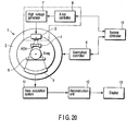
- Fig. 20 shows the configuration of the X-rays computed tomography system according to this embodiment of the invention.
- the projection data measurement system constituted by gantry 1 accommodates an x-ray source 3 that generates a cone-beam of x-ray flux approximately cone-shaped, and a two-dimensional array type x-ray detector 5 consisting of a plurality of detector elements 5A arranged in two-dimensional fashion, i.e., a plurality of elements arranged in one dimension stacked in a plurality of rows.
- a two-dimensional array type x-ray detector 5 consisting of a plurality of detector elements 5A arranged in two-dimensional fashion, i.e., a plurality of elements arranged in one dimension stacked in a plurality of rows.
- X-ray source 3 and two-dimensional array type x-ray detector 5 are installed on a rotating ring 2 in facing opposite sides of a subject, who is laid on a sliding sheet of a bed 6. Two-dimensional array type x-ray detector 5 is mounted on rotating ring 2. Each detector element will correspond with one channel.
- X-rays from x-ray source 3 are directed on to subject through an x-ray filter 4.
- X-rays that have passed through the subject are detected as an electrical signal by two-dimensional array type x-ray detector 5.
- X-ray controller 8 supplies a trigger signal to high voltage generator 7.
- High voltage generator 7 applies high voltage to x-ray source 3 with the timing with which the trigger signal is received. This causes x-rays to be emitted from x-ray source 3.
- Gantry/bed controller 9 synchronously controls the revolution of rotating ring 2 of gantry 1 and the sliding of the sliding sheet of bed 6.
- System controller 10 constitutes the control center of the entire system and controls x-ray controller 8 and gantry/bed controller 9 such that, as seen from the subject, x-ray source 3 executes so-called helical scanning, in which it moves along a helical path.
- rotating ring 2 is continuously rotated with fixed angular speed while the sliding plate is displaced with fixed speed, and x-rays are emitted continuously or intermittently at fixed angular intervals from x-ray source 3.
- the output signal of two-dimensional array type x-ray detector 5 is amplified by a data collection unit 11 for each channel and converted to a digital signal, to produce projection data.
- the projection data that is output from data collection unit 11 is fed to reconstruction processing unit 12.
- Reconstruction processing unit 12 uses the projection data to find backprojection data reflecting the x-ray absorption in each voxel.
- the imaging region (effective field of view) is of cylindrical shape of radius .omega. centered on the axis of revolution.
- Reconstruction processing unit 12 defines a plurality of voxels (three-dimensional pixels) in this imaging region, and finds the backprojection data for each voxel.
- the three-dimensional image data or tomographic image data compiled by using this backprojection data is sent to display device 14, where it is displayed visually as a three-dimensional image or tomographic image.
- One of the problems of using the weighting is that when the projection angular range (as shown in Figs. 1a and 1b) is extended, replicated invalid data have the same weight. Using such invalid data degrades image quality by introducing artifacts and increasing noise if an extrapolation method is used.
- the Applicants have discovered another weighting application as a function of the validity of the projection data. This weighted data is then combined with the overscan or extended half-scan methods, depending on the helical pitch.
- the newly discovered weighting method permits extension of the projection angular range for reconstruction, while minimizing the side effects of extrapolation or replication, as shown in Fig. 1c.
- Current experiments indicate that combination of ⁇ 0 corresponding to slightly inside of the edge of the detector and ⁇ m slightly outside of the edge achieve the best results.
- the generalized weighted Feldkamp algorithm includes the following three steps: 1) applying a weighting function to the projection data (applying the same weight to all of the detector rows), 2) filtering the data in the horizontal direction(or a filtering along the direction such as the tangent direction of the helical path), and 3) cone-beam backprojection.
- Steps 2 and 3 Filtering and Cone-Beam Backprojection
- h(•) denotes the filter function (e.g., ramp, Shepp-Logan, or the like)
- r 0 represents the radius of the cylindrical support of the object
- D represents the detector height at the iso-center (width in the z direction of the detector on the rotation center axis (z axis) ).
- the projection view data for the range is weighted (using techniques such as those described in Dennis L. Parker, "Optimal Short Scan Convolution Reconstruction for Fanbeam CT,” Med. Phys. 9(2), March/April 1982, the contents of which are herein incorporated by reference), and convolved (using techniques analogous to those described in H.H. Barrett and W. Swindell, Radiological Imaging: Theory of Image Formation, Detection, and Processing , Vol. 2, New York: Academic Press, pp 391-392 (1981), the contents of which is herein incorporated by reference) as desired prior to backprojection.
- Weighting functions used for helical scanning vary depending on helical pitch. Generally, over-scan functions are used for small helical pitch (projection range ⁇ r > 2 ⁇ ) and extended half-scan for high helical pitch ( ⁇ r ⁇ 2 ⁇ ) (See, e.g., M. D. Silver, K. Taguchi, and K. S. Han, "Field-of-view dependent helical pitch in multi-slice CT," Proc. of SPIE Med. Imag. Conf., 4320, 839-850 (2001); M. D. Silver, K. Taguchi, and I. A.
- weights are a function of ray angle, ⁇ , as well as projection angle, ⁇ , as shown in Equations 11-14 below:
- One known weighting algorithm uses pixel dependent weighting during cone-beam backprojection, as well as pixel dependent projection angular range, which is often too complicated to implement. (See, e.g., Hu et al., U. S. Pat. No. 5,430,783, the contents of which are herein incorporated by reference.)
- Another known weighting algorithm modifies extended half-scan by applying weight as a function of "pure cone-angle" to the projection data, modifying the projection data, and normalizing the weights of primary and complementary rays.
- weight as a function of "pure cone-angle"
- x ( ⁇ , ⁇ , ⁇ ) P ⁇ , ⁇ P ⁇ cot ⁇ 2 a P ⁇ , ⁇ P ⁇ cot ⁇ 2 a + P ⁇ c , ⁇ c P ⁇ cot ⁇ c 2 a , where a is a parameter for tuning the algorithm and P is the normalized helical pitch.
- Equation 15 and 16 altering the cone angle (cot ⁇ or altering the original weight as a function of normalized helical pitch does not sufficiently reduce the effect of extrapolation or replication when the cone angle ⁇ is small. Additionally, the method of Equations 15 and 16 does not consider the validity (or potential invalidity) of the data being used. It is also important to note that the parameter "a" used in Equation 16 is distinct from the a of Fig. 8b.
- One problem of the current method is that extending the projection angular range (as shown in Figs. 1a and 1b) requires the use of extrapolated (or replicated) invalid data having the same weight as the valid (measured) data (Fig. 1b). Using such invalid data degrades image quality by introducing artifacts (and increasing noise if extrapolation is used).
- the present invention relates to applying another weight as a function of the validity of projection data and combining the other weight with overscan or extended half-scan, depending on helical pitch. Therefore, it is possible to extend the projection angular range for reconstruction while minimizing side effects of extrapolation and replication (Fig. 1c).
- ⁇ r > 4 ⁇ another weighting function should be applied that normalizes the weights to the primary and complementary rays.
- the data validity weighting function is set forth in equations 18-20, below: and ⁇ m > tan -1 D / 2R .
- ⁇ is a cone angle at which the line connecting a specific ray of the cone beam and the focal point of the cone beam intersects with the plane perpendicular to the rotation axis (i.e., x axis)
- ⁇ 0 is a cone angle for the ray applied to a detecting element near one end of any element-row of the detector array.
- the cone angle ⁇ 0 is not limited in particular. Therefore, it can be of the value for the ray applied to one end of the element-row.
- the cone angle ⁇ 0 should better have an absolute value slightly smaller than the cone angle for the ray applied to one end of the element-column.
- the cone angle ⁇ m has an absolute value a little greater than the angle ⁇ 0.
- the channel corresponding to the angle ⁇ m or ⁇ 0 may be an outermost one. Nevertheless, as is known in the art, too, it is desired that either outermost channel should lie between the lines corresponding to the cone angles ⁇ 0 and ⁇ m. A part of the data, which is not actually measured of the channels lying between the lines corresponding to the angles ⁇ 0 and ⁇ m, has been generated by extrapolation or is a copy of the data obtained at either outermost channel.
- the data obtained at some of the channels lying between the lines corresponding to the cone angles ⁇ 0 and ⁇ m and the data obtained outside the line corresponding to the angle ⁇ m, which have not been actually measured, are not so reliable. They are therefore weighted less than the actually measured data.
- L z tan ⁇ ;
- L c z c tan ⁇ c .
- Equation (B8) It is useful to restrict ⁇ c as shown in Equation (B8) to avoid extraordinary cases, such as those shown in Fig. 4.
- the complementary rays may be obtained when positions of focus and detector are exchanged (as shown in Fig. 10a) or at the same projection angle but in the different rotation (as shown in Fig. 10b).
- ⁇ h ( 2 ⁇ + ⁇ )/ 2 .
- the complementary ray can be defined by using the following Equations 21 and 22.
- the projection angle and the ray angle of n-complementary ray is defined by:
- L is clipped by:
- the cone-angle for the complementary ray is:
- Equation (26a) is used to calculate the cone-angle value.
- the weighting curve shown in Fig. 8b is flat in regions where ( ⁇ > ⁇ m ), clipping the cone-angle at ⁇ m yields the same result.
- ⁇ is a cone angle at which the line connecting a specific ray of the cone beam and the focal point of the cone beam intersects with the plane perpendicular to the rotation axis (i.e., x axis)
- ⁇ 0 is a cone angle for the ray applied to a detecting element near one end of any element-row of the detector array.
- the cone angle ⁇ 0 is not limited in particular. Therefore, it can be of the value for the ray applied to one end of the element-row. Nonetheless, as known in the art, the cone angle ⁇ 0 should better have an absolute value slightly smaller than the cone angle for the ray applied to one end of the element-column.
- the angle ( ⁇ 0 + ⁇ m ) is outside only with ⁇ m more than ⁇ 0.
- the channel corresponding to the angle ( ⁇ 0 + ⁇ m ) or ⁇ 0 may be an outermost one. Nevertheless, as is known in the art, too, it is desired that either outermost channel should lie between the lines corresponding to the cone angles ⁇ 0 and ( ⁇ 0 + ⁇ m).
- the data obtained at some of the channels lying between the lines corresponding to the cone angles ⁇ 0 and ( ⁇ 0 + ⁇ m ) and the data obtained outside the line corresponding to the angle ⁇ m, which have not been actually measured, are not so reliable. They are therefore weighted less than the actually measured data.
- Equations 21-26 give a primary ray.
- the method of the present embodiment decreases weights to the invalid (extrapolated/replicated) rays and increases weight to the valid (measured) rays. Additionally, weights are normalized so that the redundancy of data is correctly compensated. Moreover, the method of the present embodiment will not change weights if all ray-sums are valid, all ray-sums are invalid, or there is no redundant data. Finally, the weight is a function of ⁇ , ⁇ , and ⁇ in all helical pitches, and smoothly changes in any direction.
- the cone angle dependent weight as described by Cone w may be arbitrary. It may include a sigmoid curve, an exponential, or the like.
- the weighting function, which is combined with Cone w may also be arbitrary. Even if cone angle dependent weight has been used, the method of the first embodiment is capable of enhancing performance by taking validity of each ray-sum into account.
- the reconstruction method of the present invention does not have to be "cone-beam,” and may include such methods as parallel-fan-beam by rebinning (sorting) cone-beam data obtained at plural focus (cone vertexes) (like fan-to-parallel beam rebinning) and the like.
- wt max has, for example, a value of 0.6, then or and or where w m is the maximum weight among all the primary and the complementary rays ( OS w ⁇ c ( n ) ⁇ Cone w ⁇ c ( n ) , ⁇ c ( n ) , ⁇ c ( n ) or MHS w ⁇ c ( n ) ⁇ Cone w ⁇ c ( n ) , ⁇ c ( n ) , ⁇ c ( n ) ).
- the method according to the above-described second aspect of the present invention provides decreased image noise.
- the noise is most effectively reduced when data are weighted equally.
- the first embodiment sometimes results in disproportionate weighting of the data, which causes increased image noise.
- By capping the value at ⁇ m it is possible to achieve a better balancing of the validity of the data, the ability to reduce image noise, and the image quality.
- the third embodiment method does not search non-existing ray-sums. For example, in a case of MHS weighting, the projection data ranges for 2 ⁇ . Therefore, it is possible to use Equation (34) instead of Equation (21), thereby reducing the number of complementary ray-sums to calculate from 3 to 2.
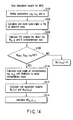
- the method for using six complementary rays all the time includes several steps.
- the method begins with step S102: Define parameters ⁇ 0 , ⁇ m , and a.
- Step S108 If w ocn , ⁇ cn , ⁇ cn ⁇ 0 , do steps S110 and S112.
- Step S110 Calculate cone-angle of complementary ray, ⁇ cn , with limitation for avoiding extraordinary cases.
- Step S112 Calculate row dependent weights w r ( ⁇ ) and w rn ( ⁇ cn ).
- Step S114 Calculate wt o , ⁇ , ⁇ by Equation (C1), shown above.
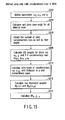
- Step S202 Define parameters ⁇ 0 , ⁇ m , and a.
- Step S204 Calculate and store cone-angle ⁇ for all of detector rows.
- Step S206 Obtain the number of valid complementary rays as well as their angles.
- Step S208 Calculate OS weights for direct ray w o , ⁇ and 2-4 complementary rays w ocn , ⁇ cn , ⁇ cn .
- Step S210 Calculate cone-angle of complementary ray, ⁇ cn , with limitation for avoiding extraordinary cases.
- Step S212 Calculate row dependent weights w r ( ⁇ ) and w rn ( ⁇ cn ).
- Step S214 Calculate wt o , ⁇ , ⁇ by Equation (C1)'.
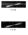
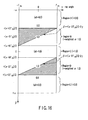
- FIG. 11-13 Examples of row-OS weight are shown in Figs. 11-13. Note that these Figs. only show detector rows used in reconstruction.
- Fig. 11b When (r2-r1) is small, we observe rapid change in view direction as well as whip-type pattern. When (r2-r1) is large, this change and whip is feathered (Fig. 11c). When r1 ⁇ 0, there is no whip and rapid change (Fig. 11d).
- Fig. 12b When (r2-r1) is small, the change in row direction is also rapid. It is smoothed when (r2-r1) is large (Fig. 12c).
- Fig. 12d (r1 ⁇ 0) can be an option, but may reduce photon utilization rate, that is, increase image noise.
- Fig. 12e small a may not be able to reduce the effect of extrapolation.
- Fig. 13 The center channel shows symmetric weighting, while (Fig. 12) shows asymmetric weight.
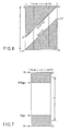
- the first formula applied is for MHS weight w p , ⁇ , ⁇ (independent of cone angle ⁇ ), as illustrated in Fig. 16, which is an alternative depiction of the MHS weight of Fig. 6.
- It is also possible to use a version for ⁇ [ 0 , ⁇ + 2 ⁇ m ].
Landscapes
- Life Sciences & Earth Sciences (AREA)
- Engineering & Computer Science (AREA)
- Health & Medical Sciences (AREA)
- Physics & Mathematics (AREA)
- Medical Informatics (AREA)
- Optics & Photonics (AREA)
- Heart & Thoracic Surgery (AREA)
- High Energy & Nuclear Physics (AREA)
- Theoretical Computer Science (AREA)
- Nuclear Medicine, Radiotherapy & Molecular Imaging (AREA)
- General Physics & Mathematics (AREA)
- Pathology (AREA)
- Radiology & Medical Imaging (AREA)
- Biomedical Technology (AREA)
- Biophysics (AREA)
- Molecular Biology (AREA)
- Surgery (AREA)
- Animal Behavior & Ethology (AREA)
- General Health & Medical Sciences (AREA)
- Public Health (AREA)
- Veterinary Medicine (AREA)
- Apparatus For Radiation Diagnosis (AREA)
Applications Claiming Priority (2)
| Application Number | Priority Date | Filing Date | Title |
|---|---|---|---|
| US10/461,401 US6917663B2 (en) | 2003-06-16 | 2003-06-16 | Cone-beam reconstruction apparatus and computed tomography apparatus |
| US461401 | 2003-06-16 |
Publications (2)
| Publication Number | Publication Date |
|---|---|
| EP1489559A1 true EP1489559A1 (fr) | 2004-12-22 |
| EP1489559B1 EP1489559B1 (fr) | 2007-10-10 |
Family
ID=33418105
Family Applications (1)
| Application Number | Title | Priority Date | Filing Date |
|---|---|---|---|
| EP04253585A Expired - Lifetime EP1489559B1 (fr) | 2003-06-16 | 2004-06-16 | Dispositif pour la reconstruction de données à faisceau conique et dispositif de tomographie par ordinateur |
Country Status (5)
| Country | Link |
|---|---|
| US (1) | US6917663B2 (fr) |
| EP (1) | EP1489559B1 (fr) |
| JP (2) | JP4612347B2 (fr) |
| CN (1) | CN1572253B (fr) |
| DE (1) | DE602004009368T2 (fr) |
Cited By (1)
| Publication number | Priority date | Publication date | Assignee | Title |
|---|---|---|---|---|
| WO2008027703A3 (fr) * | 2006-08-30 | 2008-07-03 | Gen Electric | Acquisition et reconstruction de donnees de projection au moyen d'une geometrie de tomodensitometrie stationnaire |
Families Citing this family (22)
| Publication number | Priority date | Publication date | Assignee | Title |
|---|---|---|---|---|
| US7050527B2 (en) * | 2004-02-09 | 2006-05-23 | G.E. Medical Systems Global Technology Company, Llc | Methods and apparatus for artifact reduction in cone beam CT image reconstruction |
| US7215734B2 (en) * | 2004-06-30 | 2007-05-08 | General Electric Company | Method and system for three-dimensional reconstruction of images |
| US7173996B2 (en) * | 2004-07-16 | 2007-02-06 | General Electric Company | Methods and apparatus for 3D reconstruction in helical cone beam volumetric CT |
| US7583777B2 (en) * | 2004-07-21 | 2009-09-01 | General Electric Company | Method and apparatus for 3D reconstruction of images |
| US7539281B2 (en) * | 2004-10-15 | 2009-05-26 | General Electric Company | Methods and apparatus for reconstruction in helical cone beam volumetric CT |
| US7573973B2 (en) * | 2005-05-17 | 2009-08-11 | General Electric Company | Methods and systems to facilitate reducing cone beam artifacts in images |
| CN105596022B (zh) * | 2006-02-27 | 2020-05-22 | 罗切斯特大学 | 锥束ct动态成像的方法和设备 |
| US20080056432A1 (en) * | 2006-08-30 | 2008-03-06 | General Electric Company | Reconstruction of CT projection data |
| US7616731B2 (en) * | 2006-08-30 | 2009-11-10 | General Electric Company | Acquisition and reconstruction of projection data using a stationary CT geometry |
| US7706499B2 (en) | 2006-08-30 | 2010-04-27 | General Electric Company | Acquisition and reconstruction of projection data using a stationary CT geometry |
| US8184891B2 (en) * | 2006-10-18 | 2012-05-22 | Koninklijke Philips Electronics, N.V. | Imaging system, imaging method and computer program for imaging a region of interest |
| US7542541B2 (en) * | 2006-10-20 | 2009-06-02 | General Electric Company | View weighting methods and apparatus |
| JP5161888B2 (ja) * | 2006-11-24 | 2013-03-13 | 株式会社東芝 | 円状及び直線状軌道を用いた医用撮像における断層撮影法の再構成のための方法及びシステム |
| US8494111B2 (en) * | 2007-11-02 | 2013-07-23 | Kabushiki Kaisha Toshiba | System and method for image reconstruction for helical cone beam computed tomography with factorized redundancy weighting |
| US9369962B2 (en) | 2010-05-17 | 2016-06-14 | Qualcomm Incorporated | Reducing idle mode power consumption for monitoring neighboring base stations |
| US8805037B2 (en) | 2011-05-31 | 2014-08-12 | General Electric Company | Method and system for reconstruction of tomographic images |
| JP5872212B2 (ja) * | 2011-09-08 | 2016-03-01 | 株式会社東芝 | マルチスライスct装置及びデータ前処理方法 |
| US8712134B2 (en) * | 2011-10-18 | 2014-04-29 | Kabushiki Kaisha Toshiba | Method and system for expanding axial coverage in iterative reconstruction in computer tomography (CT) |
| US8724876B2 (en) * | 2011-10-18 | 2014-05-13 | Kabushiki Kaisha Toshiba | Method and system for substantially reducing streak artifacts in helical cone beam computer tomography (CT) |
| US8837797B2 (en) * | 2012-01-10 | 2014-09-16 | Kabushiki Kaisha Toshiba | Spatial resolution improvement in computer tomography (CT) using iterative reconstruction |
| JP6181045B2 (ja) * | 2012-04-24 | 2017-08-16 | 株式会社日立製作所 | X線ct装置及び画像再構成方法 |
| CN106651753B (zh) * | 2016-09-28 | 2020-03-17 | 东软医疗系统股份有限公司 | 提高ct图像显示效果的方法及装置 |
Citations (2)
| Publication number | Priority date | Publication date | Assignee | Title |
|---|---|---|---|---|
| US6408042B1 (en) * | 2001-06-15 | 2002-06-18 | Ge Medical Systems Global Technology Company, Llc | Methods and apparatus for cone beam artifact suppression in scanning imaging systems |
| DE10244181A1 (de) * | 2002-09-23 | 2004-04-01 | Siemens Ag | Verfahren zur Bilderstellung in der Computertomographie und CT-Gerät zur Durchführung des Verfahrens |
Family Cites Families (9)
| Publication number | Priority date | Publication date | Assignee | Title |
|---|---|---|---|---|
| JP2914891B2 (ja) * | 1995-07-05 | 1999-07-05 | 株式会社東芝 | X線コンピュータ断層撮影装置 |
| US5708691A (en) | 1996-07-05 | 1998-01-13 | Kabushiki Kaisha Toshiba | X-ray computed tomographic imaging device and x-ray computed tomographic method |
| US6061423A (en) * | 1998-08-25 | 2000-05-09 | General Electric Company | Fluoroscopy image reconstruction |
| US6466640B1 (en) * | 1999-11-26 | 2002-10-15 | Kabushiki Kaisha Toshiba | Computed tomography system and method |
| US6324241B1 (en) * | 1999-12-30 | 2001-11-27 | Ge Medical Systems Global Technology Company, Llc | Method and apparatus for CT reconstruction |
| US6341154B1 (en) * | 2000-06-22 | 2002-01-22 | Ge Medical Systems Global Technology Company, Llc | Methods and apparatus for fast CT imaging helical weighting |
| DE10204926A1 (de) * | 2002-02-07 | 2003-08-21 | Philips Intellectual Property | Sequentielles Computertomographie-Verfahren |
| JP4360817B2 (ja) * | 2002-10-18 | 2009-11-11 | 株式会社日立メディコ | 放射線断層撮影装置 |
| US6845144B2 (en) * | 2003-02-08 | 2005-01-18 | Ge Medical Systems Global Technology Company, Llc | Three dimensional back projection method and an X-ray CT apparatus |
-
2003
- 2003-06-16 US US10/461,401 patent/US6917663B2/en not_active Expired - Lifetime
-
2004
- 2004-06-11 JP JP2004174451A patent/JP4612347B2/ja not_active Expired - Lifetime
- 2004-06-15 CN CN2004100593200A patent/CN1572253B/zh not_active Expired - Fee Related
- 2004-06-16 DE DE602004009368T patent/DE602004009368T2/de not_active Expired - Lifetime
- 2004-06-16 EP EP04253585A patent/EP1489559B1/fr not_active Expired - Lifetime
-
2010
- 2010-08-06 JP JP2010177925A patent/JP2010240498A/ja active Pending
Patent Citations (2)
| Publication number | Priority date | Publication date | Assignee | Title |
|---|---|---|---|---|
| US6408042B1 (en) * | 2001-06-15 | 2002-06-18 | Ge Medical Systems Global Technology Company, Llc | Methods and apparatus for cone beam artifact suppression in scanning imaging systems |
| DE10244181A1 (de) * | 2002-09-23 | 2004-04-01 | Siemens Ag | Verfahren zur Bilderstellung in der Computertomographie und CT-Gerät zur Durchführung des Verfahrens |
Non-Patent Citations (3)
| Title |
|---|
| FELDKAMP L A ET AL: "Practical cone-beam algorithm", JOURNAL OF THE OPTICAL SOCIETY OF AMERICA - A, OPTICAL SOCIETY OF AMERICA, WASHINGTON, US, vol. 1, no. 6, 1 June 1984 (1984-06-01), pages 612 - 619, XP002085783, ISSN: 1084-7529 * |
| STIERSTORFER K ET AL: "Weighted FBP-a simple approximate 3D FBP algorithm for multislice spiral CT with good dose usage for arbitrary pitch", PHYSICS IN MEDICINE AND BIOLOGY IOP PUBLISHING UK, vol. 49, no. 11, 19 May 2004 (2004-05-19), pages 2209 - 2218, XP002299944, ISSN: 0031-9155 * |
| TAGUCHI K ET AL: "A new weighting scheme for cone-beam helical CT to reduce the image noise", PHYSICS IN MEDICINE AND BIOLOGY IOP PUBLISHING UK, vol. 49, no. 11, 19 May 2004 (2004-05-19), pages 2351 - 2364, XP002299943, ISSN: 0031-9155 * |
Cited By (1)
| Publication number | Priority date | Publication date | Assignee | Title |
|---|---|---|---|---|
| WO2008027703A3 (fr) * | 2006-08-30 | 2008-07-03 | Gen Electric | Acquisition et reconstruction de donnees de projection au moyen d'une geometrie de tomodensitometrie stationnaire |
Also Published As
| Publication number | Publication date |
|---|---|
| US6917663B2 (en) | 2005-07-12 |
| JP2005007169A (ja) | 2005-01-13 |
| DE602004009368T2 (de) | 2008-07-10 |
| US20040252806A1 (en) | 2004-12-16 |
| EP1489559B1 (fr) | 2007-10-10 |
| JP2010240498A (ja) | 2010-10-28 |
| CN1572253A (zh) | 2005-02-02 |
| DE602004009368D1 (de) | 2007-11-22 |
| CN1572253B (zh) | 2012-04-25 |
| JP4612347B2 (ja) | 2011-01-12 |
Similar Documents
| Publication | Publication Date | Title |
|---|---|---|
| EP1489559B1 (fr) | Dispositif pour la reconstruction de données à faisceau conique et dispositif de tomographie par ordinateur | |
| EP1643446B1 (fr) | Procédé pour la reconstruction d'images et appareil pour la tomographie par ordinateur à rayons X | |
| US7903779B2 (en) | Apparatus and method for reconstruction of volumetric images in a divergent scanning computed tomography system | |
| US6490333B1 (en) | Methods and apparatus for cone-tilted parallel sampling and reconstruction | |
| US6256366B1 (en) | Apparatus and method for reconstruction of volumetric images in a computed tomography system using sementation of slices | |
| US6201849B1 (en) | Apparatus and method for reconstruction of volumetric images in a helical scanning cone-beam computed tomography system | |
| US6778630B2 (en) | Method and system for reconstructing computed tomography images using redundant data | |
| US20160367212A1 (en) | Method and apparatus for iteratively reconstructing tomographic images from electrocardiographic-gated projection data | |
| Bruder et al. | Single-slice rebinning reconstruction in spiral cone-beam computed tomography | |
| US6426989B2 (en) | Computed tomography method | |
| US20110103662A1 (en) | Method for circular scan reconstruction in computed tomography and computed tomographic device | |
| EP1663004A2 (fr) | Methode de tomodensitometrie utilisant un faisceau conique de rayons | |
| JP5133690B2 (ja) | ボクセルに依存する補間を用いる画像再構成 | |
| JPH09285460A (ja) | 物体の断層写真画像を発生するシステム | |
| US8494111B2 (en) | System and method for image reconstruction for helical cone beam computed tomography with factorized redundancy weighting | |
| US20040114707A1 (en) | Method of creating images in computed tomography (CT), and CT device | |
| EP0989521B1 (fr) | Réconstruction d'image fluoroscopique | |
| JPH119582A (ja) | X線コンピュータ断層撮影装置 | |
| Shechter et al. | The frequency split method for helical cone‐beam reconstruction | |
| US6999550B2 (en) | Method and apparatus for obtaining data for reconstructing images of an object | |
| US8315351B2 (en) | System and method for tomographic reconstruction utilizing circular trajectory and scanogram to reduce artifacts | |
| US20040264630A1 (en) | Imaging method for a multi-slice spiral CT scan, and a computer tomography unit for carrying out this method | |
| US7539281B2 (en) | Methods and apparatus for reconstruction in helical cone beam volumetric CT | |
| Hein et al. | Tilted helical Feldkamp cone-beam reconstruction algorithm for multislice CT | |
| Hsieh | Reconstruction algorithm for single circular orbit cone beam scans |
Legal Events
| Date | Code | Title | Description |
|---|---|---|---|
| PUAI | Public reference made under article 153(3) epc to a published international application that has entered the european phase |
Free format text: ORIGINAL CODE: 0009012 |
|
| 17P | Request for examination filed |
Effective date: 20040624 |
|
| AK | Designated contracting states |
Kind code of ref document: A1 Designated state(s): AT BE BG CH CY CZ DE DK EE ES FI FR GB GR HU IE IT LI LU MC NL PL PT RO SE SI SK TR |
|
| AX | Request for extension of the european patent |
Extension state: AL HR LT LV MK |
|
| 17Q | First examination report despatched |
Effective date: 20050613 |
|
| AKX | Designation fees paid |
Designated state(s): DE FR GB NL |
|
| 17Q | First examination report despatched |
Effective date: 20050613 |
|
| GRAP | Despatch of communication of intention to grant a patent |
Free format text: ORIGINAL CODE: EPIDOSNIGR1 |
|
| GRAS | Grant fee paid |
Free format text: ORIGINAL CODE: EPIDOSNIGR3 |
|
| GRAA | (expected) grant |
Free format text: ORIGINAL CODE: 0009210 |
|
| AK | Designated contracting states |
Kind code of ref document: B1 Designated state(s): DE FR GB NL |
|
| REG | Reference to a national code |
Ref country code: GB Ref legal event code: FG4D |
|
| REF | Corresponds to: |
Ref document number: 602004009368 Country of ref document: DE Date of ref document: 20071122 Kind code of ref document: P |
|
| ET | Fr: translation filed | ||
| PLBE | No opposition filed within time limit |
Free format text: ORIGINAL CODE: 0009261 |
|
| STAA | Information on the status of an ep patent application or granted ep patent |
Free format text: STATUS: NO OPPOSITION FILED WITHIN TIME LIMIT |
|
| 26N | No opposition filed |
Effective date: 20080711 |
|
| REG | Reference to a national code |
Ref country code: GB Ref legal event code: 746 Effective date: 20090717 |
|
| REG | Reference to a national code |
Ref country code: FR Ref legal event code: PLFP Year of fee payment: 13 |
|
| REG | Reference to a national code |
Ref country code: GB Ref legal event code: 732E Free format text: REGISTERED BETWEEN 20160818 AND 20160824 |
|
| REG | Reference to a national code |
Ref country code: NL Ref legal event code: PD Owner name: TOSHIBA MEDICAL SYSTEMS CORPORATION; JP Free format text: DETAILS ASSIGNMENT: VERANDERING VAN EIGENAAR(S), OVERDRACHT; FORMER OWNER NAME: TOSHIBA MEDICAL SYSTEMS CORPORATION Effective date: 20160627 |
|
| REG | Reference to a national code |
Ref country code: FR Ref legal event code: TP Owner name: TOSHIBA MEDICAL SYSTEMS CORPORATION, JP Effective date: 20160830 |
|
| REG | Reference to a national code |
Ref country code: DE Ref legal event code: R081 Ref document number: 602004009368 Country of ref document: DE Owner name: TOSHIBA MEDICAL SYSTEMS CORPORATION, OTAWARA-S, JP Free format text: FORMER OWNERS: KABUSHIKI KAISHA TOSHIBA, TOKIO/TOKYO, JP; TOSHIBA MEDICAL SYSTEMS CORPORATION, OTAWARA-SHI, TOCHIGI-KEN, JP Ref country code: DE Ref legal event code: R082 Ref document number: 602004009368 Country of ref document: DE Representative=s name: KRAMER BARSKE SCHMIDTCHEN PATENTANWAELTE PARTG, DE |
|
| REG | Reference to a national code |
Ref country code: FR Ref legal event code: PLFP Year of fee payment: 14 |
|
| REG | Reference to a national code |
Ref country code: FR Ref legal event code: PLFP Year of fee payment: 15 |
|
| PGFP | Annual fee paid to national office [announced via postgrant information from national office to epo] |
Ref country code: NL Payment date: 20210615 Year of fee payment: 18 Ref country code: DE Payment date: 20210518 Year of fee payment: 18 Ref country code: FR Payment date: 20210513 Year of fee payment: 18 |
|
| PGFP | Annual fee paid to national office [announced via postgrant information from national office to epo] |
Ref country code: GB Payment date: 20210520 Year of fee payment: 18 |
|
| REG | Reference to a national code |
Ref country code: DE Ref legal event code: R119 Ref document number: 602004009368 Country of ref document: DE |
|
| REG | Reference to a national code |
Ref country code: NL Ref legal event code: MM Effective date: 20220701 |
|
| GBPC | Gb: european patent ceased through non-payment of renewal fee |
Effective date: 20220616 |
|
| PG25 | Lapsed in a contracting state [announced via postgrant information from national office to epo] |
Ref country code: NL Free format text: LAPSE BECAUSE OF NON-PAYMENT OF DUE FEES Effective date: 20220701 |
|
| PG25 | Lapsed in a contracting state [announced via postgrant information from national office to epo] |
Ref country code: FR Free format text: LAPSE BECAUSE OF NON-PAYMENT OF DUE FEES Effective date: 20220630 |
|
| PG25 | Lapsed in a contracting state [announced via postgrant information from national office to epo] |
Ref country code: GB Free format text: LAPSE BECAUSE OF NON-PAYMENT OF DUE FEES Effective date: 20220616 Ref country code: DE Free format text: LAPSE BECAUSE OF NON-PAYMENT OF DUE FEES Effective date: 20230103 |